Inserting elements for graphical layouts of installation details
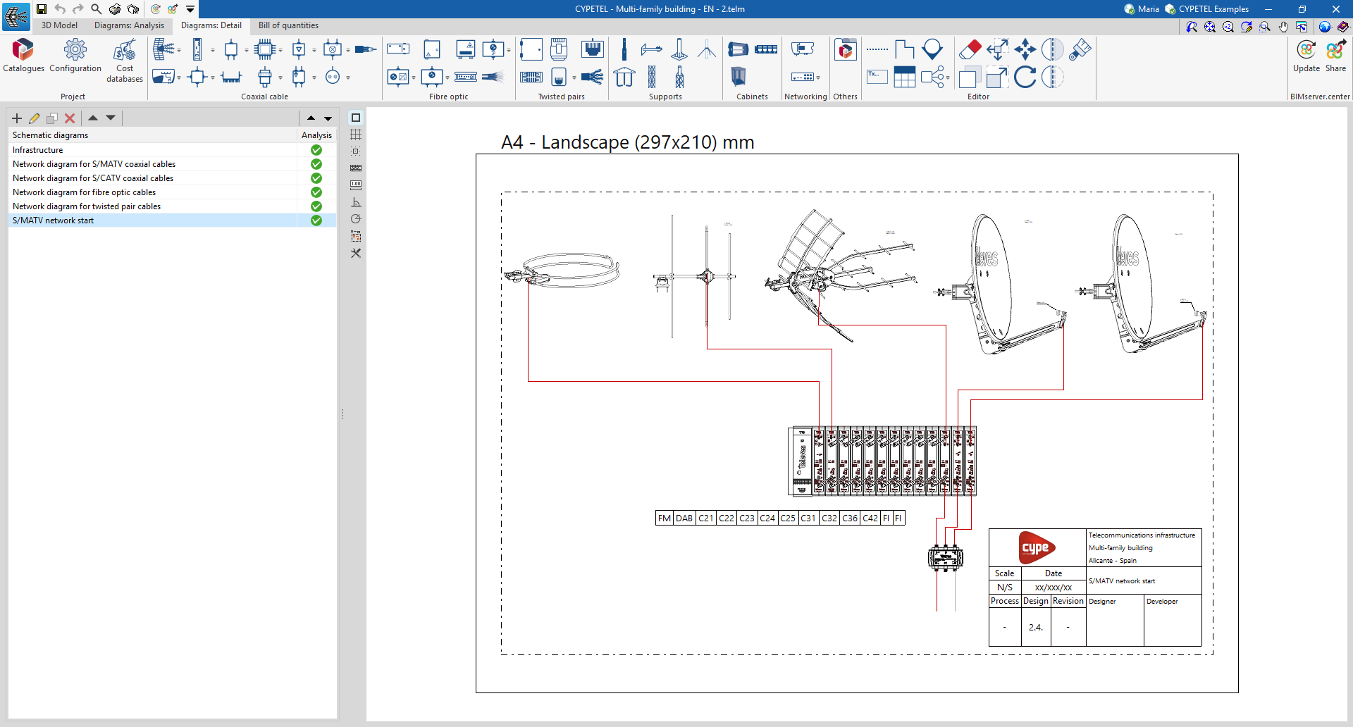
The "Diagrams: Detail" tab allows you to manually generate detailed diagrams of the telecommunications installation using the available drawing tools:
- To create diagrams from scratch, you first create the pages in the required formats using the options on the left-hand side. You then add the diagram elements to the workspace on the right-hand side using the options on the top toolbar.
The main toolbar on the "Diagrams: Detail" tab contains a range of elements for creating graphical layouts of telecommunications installation details, enabling the design of racks or headends. These elements are divided into the following groups:

Coaxial cable
From the "Coaxial cable" section, you can add the following elements to the installation:
- Collection system
- Processing headends
- Delivery drivers
- Multiswitch
- Line amplifiers
- Mixers
- Coaxial cable
- Headend amplification
- Taps
- Multi ATE ATI
- Fittings
- PAU
- Outlets
Optical fibre
From the "Fibre optics" section, you can add the following elements to the installation:
- Main fibre-optic register
- Secondary register
- Fibre-optic PAU
- Fittings
- Optical / Coaxial converters
- Splitters
- ONT
- Fibre-optic cable
Twisted pairs
From the "Twisted pairs" section, you can add the following elements to the installation:
- Main terminal enclosure/panel
- Connectors
- Outlets
- Power strip
- PAU / Multiplexer
- Twisted pair cable
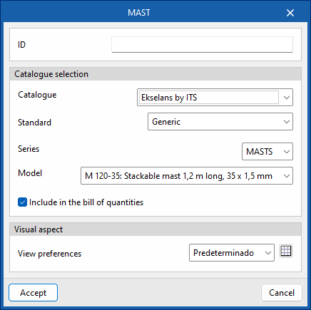
Supports
From the "Supports" section, you can add the following elements to the installation:
- Mast
- Mast support
- Antenna support
- Wind kit
- Base (Tower)
- Bottom/intermediate span (Tower)
- Top span (Tower)
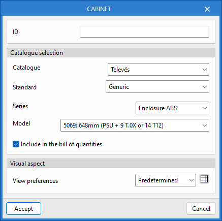
Cabinets
From the "Cabinets" section, you can add the following elements to the installation:
- Chest
- 19-inch panel
- 19-inch rack
Networking
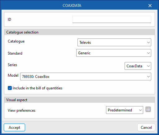
From the "Networking" section, you can add the following elements to the installation:
- CoaxDATA
- FibreData GPON
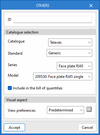
Others
From the "Others" section, you can add other elements from the catalogues to the installation.