Defining the general project settings
The "Project" panel is located on the main toolbar of the "3D model", "Diagrams: Analysis" and "Diagrams: Detail" tabs. From this panel, you can define the general project options:


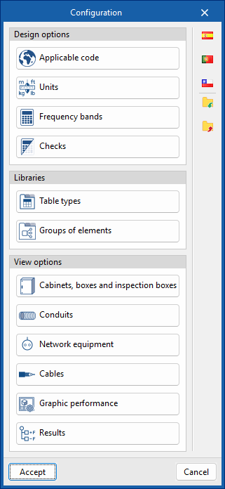
Configuration
From the "Configuration" dialogue box, you can load a predefined configuration (using the options on the right) and/or customise it.
The options available in this dialogue box are:
- Design options
- Applicable code
Selects the codes—from those included in the program—that affect the filtering of product selections and the generation of project lists. As it is linked to the country of application, it also determines the available channels, standards and pricing options, adapting the program’s content to local conditions. - Units
Configures the units, labels and number of decimal places for each of the quantities relating to the telecommunications installation.
If you use the "Import one of the predefined unit systems" option, available on the right-hand side of the panel, you can import one of the following unit systems:- International System
Imports units from the International System. - I-P System
Imports units from the I-P (Inch-Pound) system or the imperial system.
- International System
- Frequency bands
Sets the operating band limits, the lower frequency (MHz) and the upper frequency (MHz) for MATV, SMATV and CATV. - Checks
Configures the checks to be carried out for different telecommunications networks (coaxial cable, fibre optic and twisted-pair copper).- For coaxial cable networks, the following parameters can be tested: "Attenuation", "Power", "Carrier-to-noise ratio", "Intermodulation ratio", "Slope" and "Length".
- For fibre-optic networks: "Attenuation" and "Length".
- For copper twisted-pair networks: "Attenuation" and "Length".
- Applicable code
- Libraries
- Table types
Manages the captions or tables added to the diagrams using the "Add table" option in the "Edit" group on the main toolbar, in both the "Diagrams: Analysis" and "Diagrams: Detail" tabs. - Groups of elements
Manages the element groups created in the workspace using the "Groups of elements" option in the "Edit" group on the main toolbar, in both the "Diagrams: Analysis" and "Diagrams: Detail" tabs.
- Table types
- Display options
- Cabinets, boxes and inspection boxes
Configures the graphical representation of these elements, both on screen and on drawings. You can adjust the colour of the equipment, the visible information label, and the display or size of the reference, the catalogue/selection and the dimensions. Furthermore, it is possible to define different styles for each type of element. - Conduits
Configures the graphical representation of pipes, both on screen and on drawings. You can adjust their colour and thickness, the visible information label, and the display or size of the reference, length, catalogue/selection and dimensions. Furthermore, it is possible to define different styles for each type of pipe. - Network equipment
Configures the graphical representation of these elements, both on screen and on drawings. You can adjust the colour of the equipment, the visible information label, and the display or size of the reference and catalogue/selection. Furthermore, it is possible to define different styles for each type of equipment. - Cables
Configures the graphical representation of cables, both on screen and in drawings. You can adjust their colour and thickness, the visible information label, and the display or design of the reference, the length, and the catalogue/selection. Furthermore, it is possible to define different styles for each type of cable.
- Graphic performance
Choose whether the elements in the "Diagrams: Detail" tab are displayed in detail—i.e., at their original resolution—or in a simplified form, which will speed up the program’s performance. You can also set the visibility of the tables, choosing either "Always visible" or "Visible only when displaying results".
- Results
Configures the graphical representation of the most favourable and least favourable elements in the analysis results for telecommunications installation diagrams, by defining their colours and symbols.
- Cabinets, boxes and inspection boxes