Network start
Next to the "Infrastructure" section of the main toolbar on the "Diagrams: Analysis" tab is the "Network start" option. This tool acts as the network header for any telecommunications technology: coaxial cable, fibre optic or copper pairs.

In the "Network start" dialogue box, you must enter the following parameters:
- ID
Allows you to assign a name to the diagram. - "Coaxial cable" tab
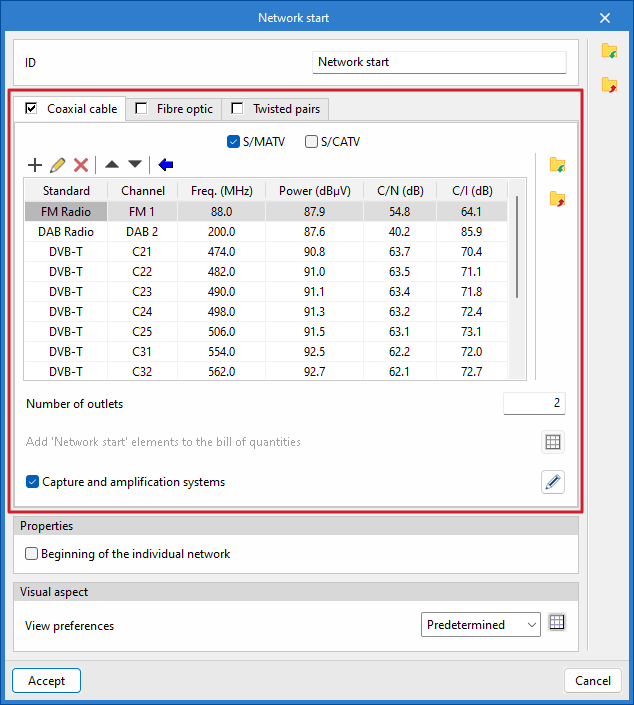
Defines the headend of a coaxial cable network.- S/MATV / S/CATV
Selects whether the network will be of the "S/MATV" type (terrestrial and satellite signal reception system), "S/CATV" type (broadband system using coaxial cable), or both. - Add
Adds new channels to the list, specifying the standard, the channel (frequency band and specific frequency), the power, the carrier-to-noise ratio and the carrier intermodulation level. Once the channels have been added to the list, you can edit, delete or move the selected item in the list. - Automatic channel list update
Automatically adds new channels to the list by selecting from predefined options based on the transmission standard. - Number of outlets
Specifies the number of outputs that the network node will have in the diagram. - Add 'Network start' elements to the bill of quantities
This option is only enabled if "S/CATV" is selected, and allows you to add elements that will subsequently be included in the project bill of quantities and the materials table. - Capture and amplification systems
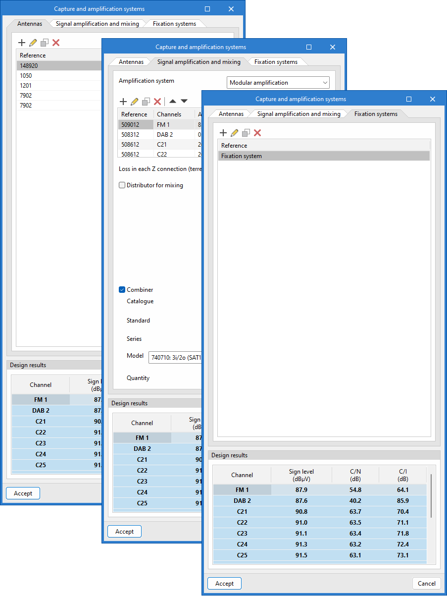
Defines a pickup and amplification system and, depending on the system selected, updates the channel list with the calculated values. From the dialogue box that opens with the same name, you can access the following tabs:- Antennas
Adds antennas, specifying their type, the repeater (optional) they are aimed at, the channels they receive, and the cable connecting them to the amplification system. - Signal amplification and mixing
Choose between the different amplification systems – "Modular amplifier", "Broadband amplifier" or "Amplifier unit" – define channels and other parameters, such as the gain value or losses in each Z connection, and configure connections for mixing terrestrial and satellite signals. - Fixation systems
Configures antenna mounting systems, specifying the wind speed and antenna locations to calculate the resulting moment. It also indicates whether a mast base, turret, wind brace, or other mounting is used.
- Antennas
- S/MATV / S/CATV
| Note: |
|---|
| You can use the following equivalents to identify the names of coaxial cable networks by analogy with those specified in Spanish regulations: S/MATV (Single Master TV Antenna) = RTV (Terrestrial and Satellite Radio and Television Services) S/CATV (Single Community Antenna Television) = TBA Coaxial (Broadband Telecommunications) |
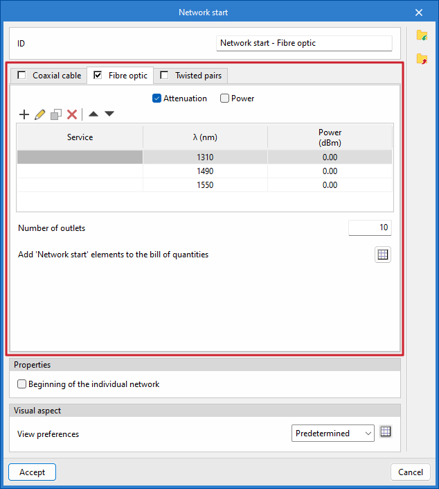
- "Fibre optic" tab
Defines the headend of a fibre-optic cable network or a hybrid fibre-coaxial (HFC) network.- Attenuation / Power
Choose between an "Attenuation" network (broadband networks) or a "Power" network (HFC networks). - Add
Adds new services to the list by specifying the wavelengths and power levels. Once the services have been added to the list, you can edit, copy, delete or move the selected item from the list. - Number of outlets
Specifies the number of outlets that the network node will have in the diagram. - Add 'Network start' elements to the bill of quantities
This option is only enabled if 'Attenuation' is selected, and allows you to add elements that will subsequently be included in the project quote and the materials schedule. - Frequency plan
This option is only enabled if "Power" is selected, and allows you to set a frequency plan for the calculation.
- Attenuation / Power
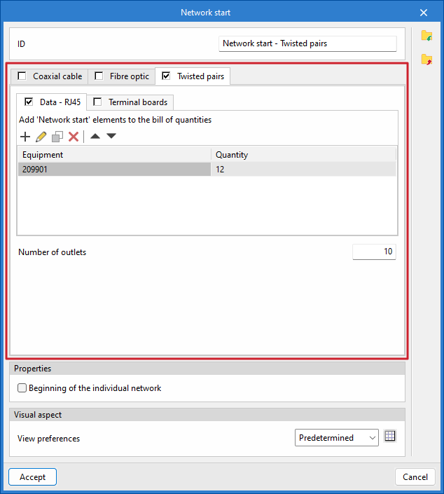
- "Copper pairs" tab
Defines the header for a copper-pair cable network.- Data - RJ45 / Patch panels
Includes elements in the network header: "Data - RJ45", "Patch panels" or both. - Add
Adds new "Network Start" elements to the bill of quantities by selecting them from the catalogue and specifying the quantity. Once the equipment has been added to the list, you can edit, copy, delete or move the selected item from the list. - Number of outlets
Specifies the number of outlets that the network node will have in the diagram.
- Data - RJ45 / Patch panels
- Start of the individual network
This allows the common areas of the building to be distinguished from the private areas. - Display preferences
Selects the display style in the diagram.
Once the network start point for the selected telecommunications technology has been defined, click "Accept", and it will be placed on the diagram.