Managing views
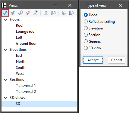
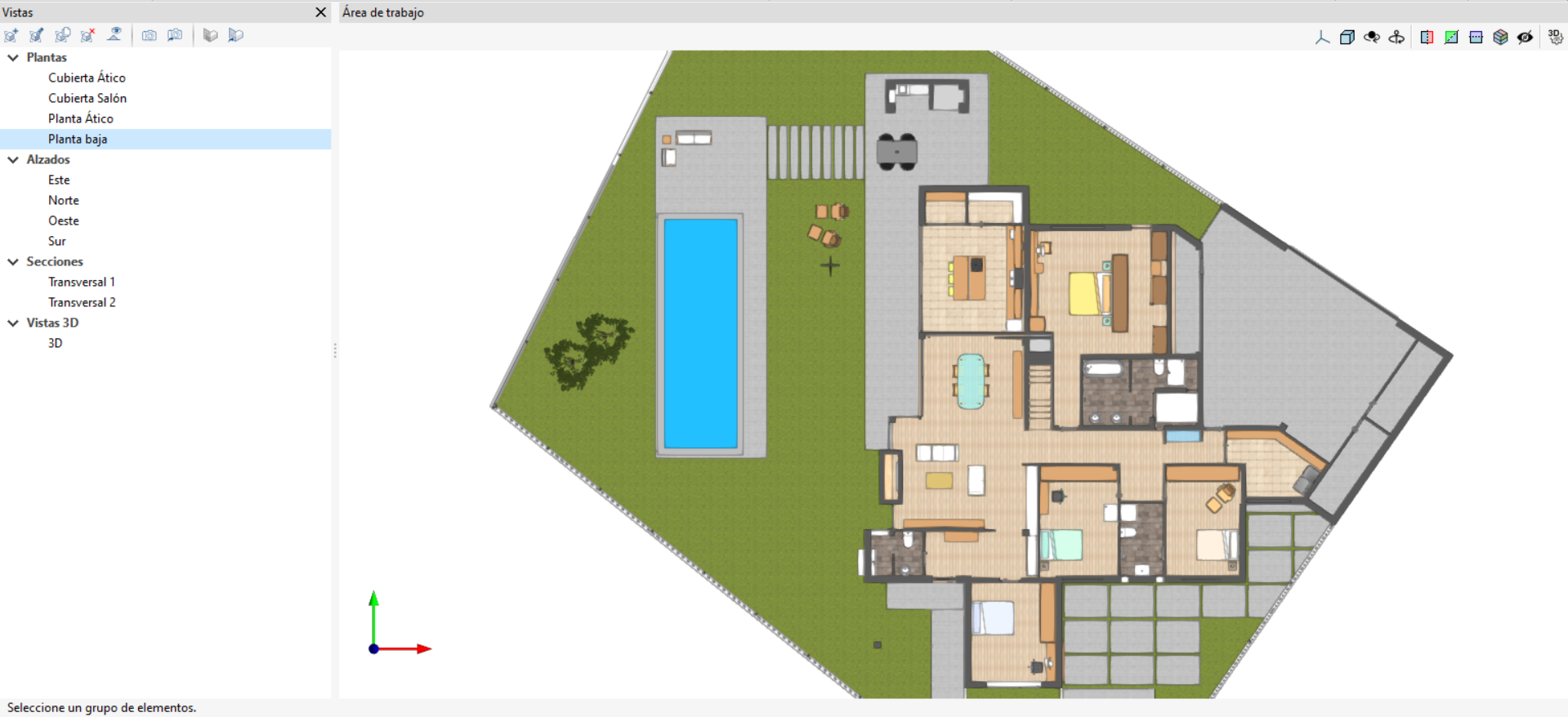
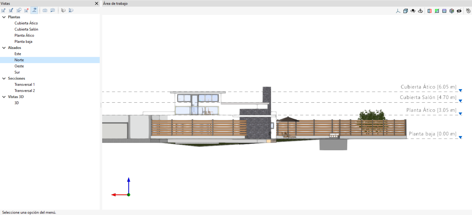
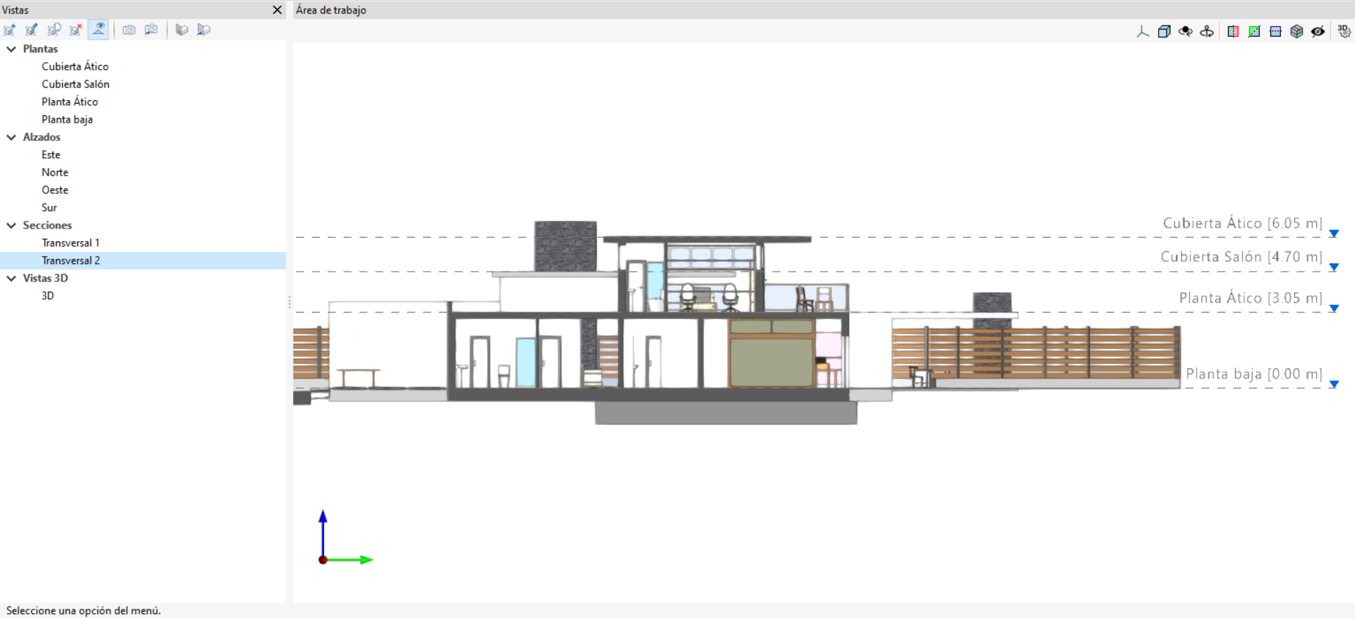
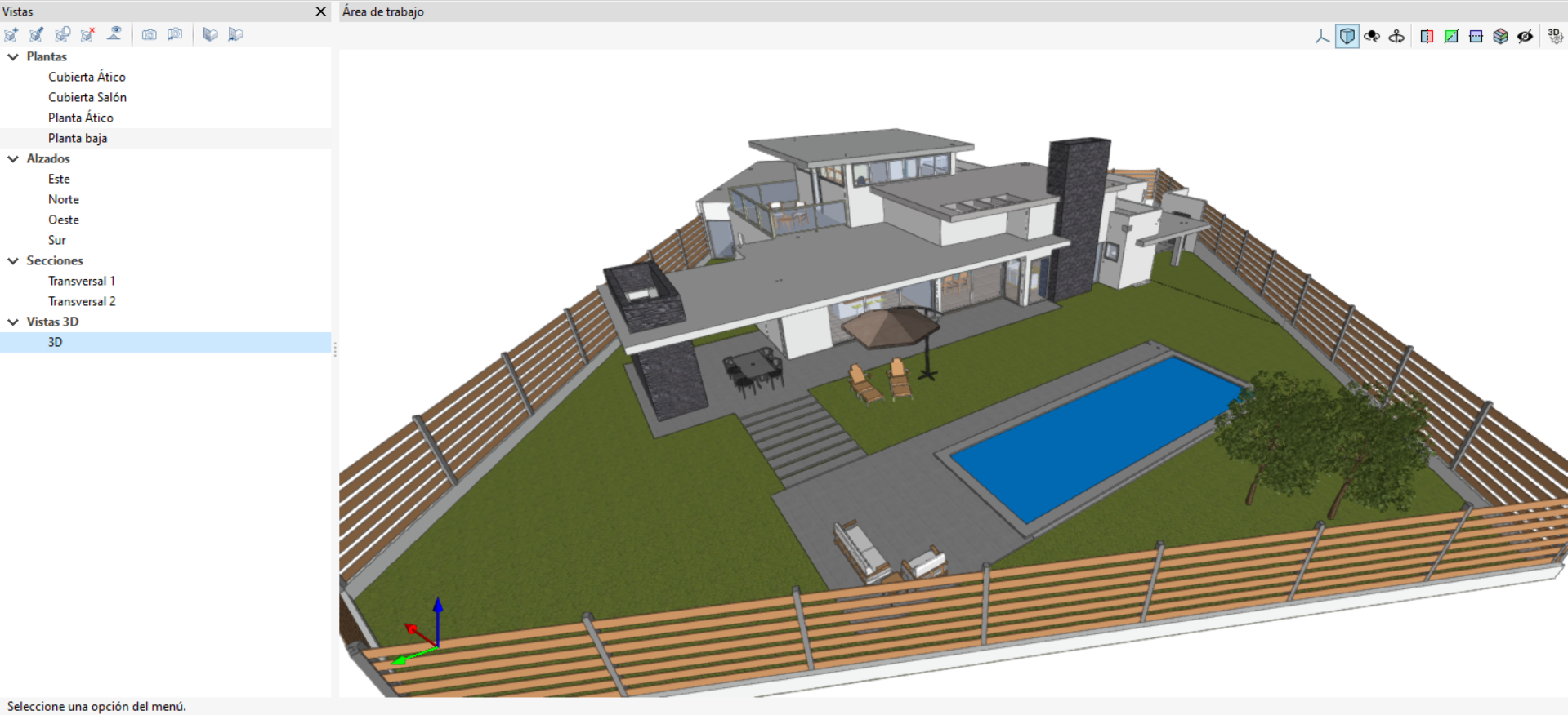
Programs with the "Views" section can create different views to make navigation and the architectural modelling process easier. You can create the following types: floor, reflected ceiling, elevation, section, generic and 3D view.
The following options are also available in the top toolbar:
- Create
Create a new 2D or 3D view of the model. - Edit
Modify the properties of the current view. - Duplicate
Copy the current view. - Delete
Delete the current view. - Show references
Display references to other views in the active view. - Save the start scene
Set the current position of the view as the start scene. - Go to start scene
Set the current view to the starting scene. - Define
Specify the workplane associated with the current view. The work plane serves as the basis for the entry of the model components. - Go to the workplane
Align the current view with the position of the work plane.
"General configuration" tab
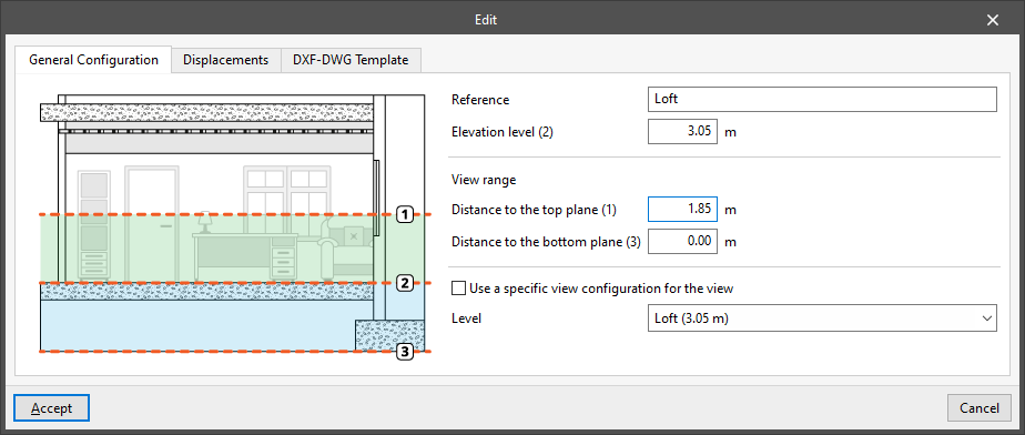
When you "Edit" each view, you can adjust the following settings in the "General settings" tab:
- Reference
View reference. - Use a specific display configuration for the view (optional)
When this option is enabled, the text "View" will appear in the "Read elements" menu, and its settings will apply only to the selected view.
If this option remains disabled, the text "View" will not be displayed, and the "Read elements" settings for the entire project will be visible and can be adjusted.
The following fields are displayed in the floor plans:
- Elevation level
The elevation where the view is located, measured relative to the general horizontal XY plane. - Level
Select the level associated with the view. This ensures that this level is automatically applied to any elements added to that view, provided that automatic elevation detection is not used.
| Note: |
|---|
| Floors form an internal data structure within the building model, whilst floor plans are simply partial representations of the model on screen. |
In the 2D views, the following section appears:
- View range
These values specify the distance to each of the planes from the view origin.
All view types, except for the 3D view, are associated with a region bounded by two planes, which determines which elements will be displayed within it.
For example, plan views will show the elements bounded and cropped by two planes situated at the specified "Distance to the top plane" and "Distance to the bottom plane", measured from the "Level dimension".
In elevation views, section views and generic views, the rear plane is the one perpendicular to the viewing direction in the positive direction. The front plane is the same, but in the negative direction.
"Displacements" tab
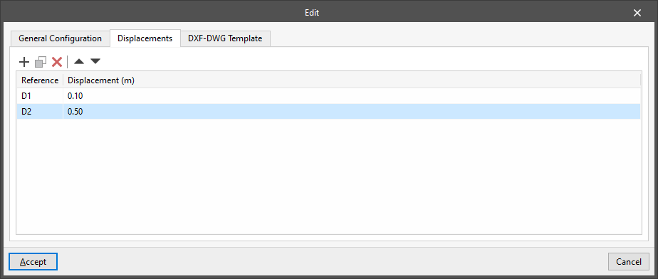
In this tab, you can create and manage displacements associated with the view, which can be loaded and used when entering elements into the view using the relevant option.
These displacements are applied to the level or position dimension of the view plane.
"DXF-DWG Template" tab
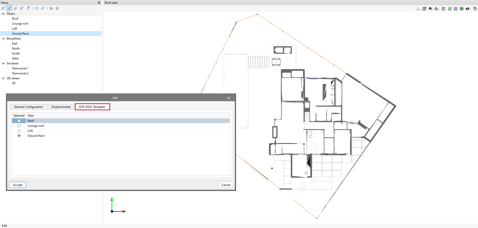
From the "Views" section, whilst creating or editing a view, you can manage the visibility of templates on the "DXF-DWF Template" tab.
This tab displays a report of all the templates imported into the project.
Ticking the box will display the template on the assigned floor plan.
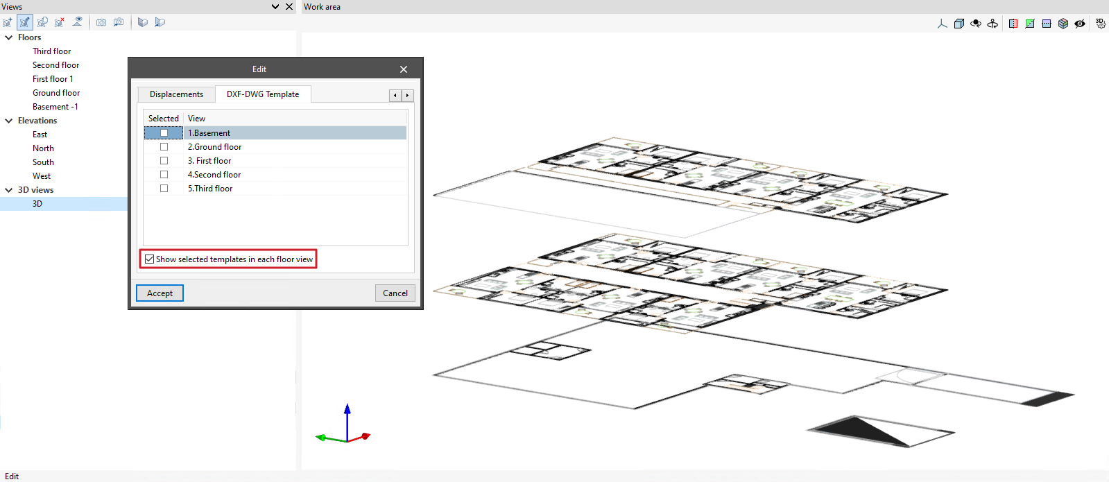
Furthermore, in 3D views, you can enable the "Show selected templates in each floor view" option.
When this option is ticked, the templates visible in each floor plan view will be displayed in the 3D view and at the corresponding dimension.
| More information: |
|---|
| The following link explains how to import DXF, DWG, PDF and JPG drawings into the project. |