Program properties
CYPE Construction Systems allows users to indicate the following properties of the construction solutions of the project:
- General description of the systems by defining their type and construction properties.
- Definition of the layers that make up the system, by indicating their thickness, materials and properties.
- Relationship with the construction systems and the elements of the architectural BIM model.
Main features of CYPE Construction Systems
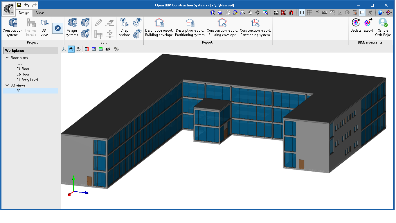
User interface
The toolbar of CYPE Construction Systems if divided into two tabs:
- Design
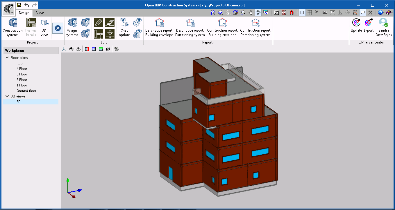
The construction systems that intervene in the project are specified in this tab. To do so, the program has a library of different typologies in which the properties of all the system classes are defined, so these can then be applied to each component of the building. - View
This tab contains the tools that are required to configure the different project views. Users can generate different 2D and 3D views of the building. The purpose of each view is to aid users' interaction with the model in a different way. All the views that are generated appear in a list on the left of the application's workspace.
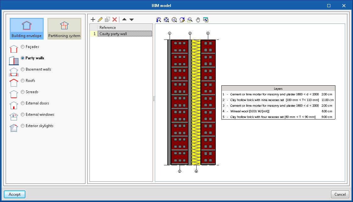
BIM model
Using the "BIM model" option of the "Design" toolbar, users can enter the typologies of the construction systems that are going to be used in the project. These are grouped based on the following classification:
- Building envelope
- Façades
- Party walls
- Basement walls
- Roofs or Screeds
- Exterior doors
- Exterior windows
- Exterior skylights
- Partitioning system
- Partitions
- Floor slabs
- Suspended ceilings
- Thermal breaks
- Interior doors
- Interior windows
- Interior skylights
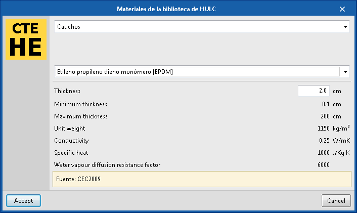
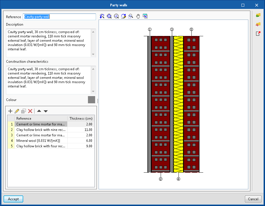
The general properties of each construction system can be indicated using the "Description" and "Construction characteristics" fields. Furthermore, for elements made up of several layers, the application allows users to specify their material properties.
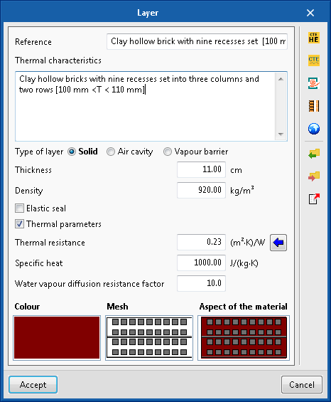
Each layer has a description and a group of parameters related to its physical properties such as its thickness and density. It is also possible to indicate whether there is an elastic seal along the perimeter of the layer. Users can also, optionally, enter values to define its thermal properties.
To represent the system in the 3D view and in the justification reports, a colour can be indicated for the complete system and a colour and weave for each layer.
All the information of a construction system or any of its layers can be exported to a file to be able to use it in multiple projects.
The application includes, by default, materials for the layers based on standards and other official documents, with which users can define their construction systems.

Assigning construction systems
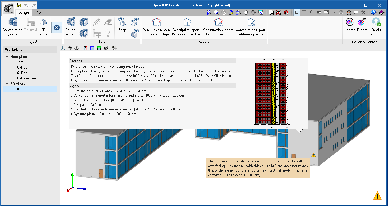
CYPE Construction Systems integrates the construction elements that have been defined in the architectural model of the BIM project into the application. Users can establish a link between the elements and the construction systems that have already been defined. This way, the selected systems can be displayed in the 3D view and the application will inform users of any possible issues such as a difference between the total thickness of the construction system compared to that of the associated architectural element.
Thermal breaks
Thermal bridges are areas of the thermal envelope of the building where the construction uniformity varies (changes in the thickness of walls, in the materials used, penetration of construction elements with different conductivity, etc.). These areas have a lower thermal resistance than that of the rest of the envelope and therefore represent an increase in heat loss.
Using CYPE Construction Systems, users have the possibility to enter thermal breaks in floor slabs. This way, the continuity of the insulation in the building is ensured at the bridges.
Thermal breaks with different linear thermal transmittance values can be defined to place them at thermal bridges of the same type.

Documents
Reports
Once the construction systems have been defined, CYPE Construction Systems automatically generates the following justification reports of the project:
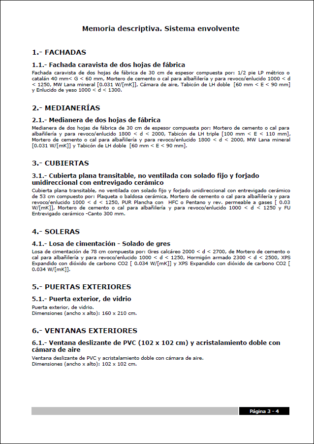
- Descriptive report. Building envelope
Report that contains the definition of the elements that make up the envelope of the building.
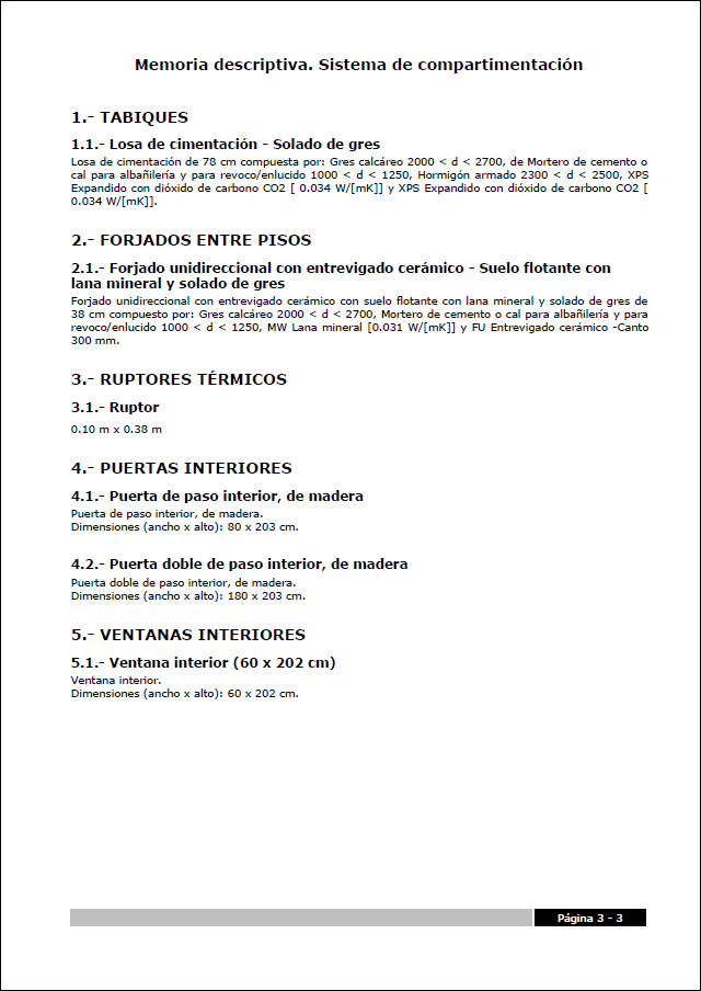
- Descriptive report. Partitioning system
Report that contains the definition of the elements that make up the partitioning system of the building.
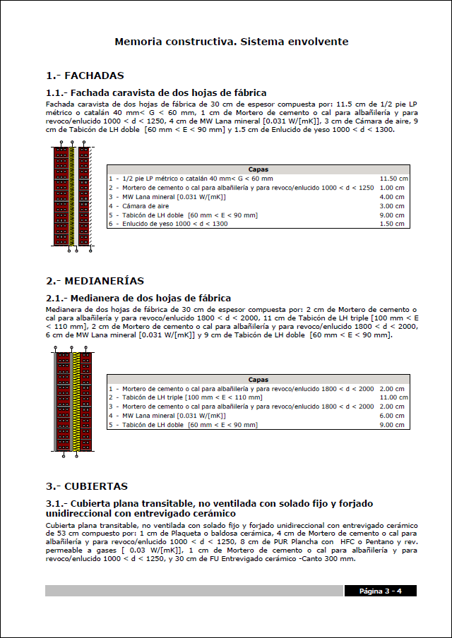
- Construction report. Building envelope
Report that describes the construction properties and layers of the elements of the building envelope.
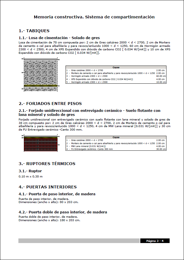
- Construction report. Partitioning system
Report that describes the construction properties and layers of the elements of the partitioning system of the building.
These documents can be printed directly from the program or exported to different formats (TXT, HTML, RTF, DOCX, PDF).
3D Information
CYPE Construction Systems generates three standard gLTF format files that correspond to the three 3D views of the elements that have been defined in the application.
- Construction systems
Allows users to view construction systems in the colour that has been defined in their properties.
- Layers
Displays each layer of the construction systems in the colour that has been defined it its properties.
- Type
Shows construction systems in the colour that has been defined for their type.
The components of the gLTF file contain additional information that can be displayed in the viewer of the BIMserver.center platform or in other CYPE applications that are able to read this format.


