
Introduction
Open BIM Site is a program aimed at defining the initial conditions of a project site. With this tool, users can establish the geographical location of the models, manage different types of maps, enter topographic surfaces and add elements specific to the site, such as parcels and buildings.
Open BIM Site is a program with an international scope, as users can specify the site conditions of a construction project anywhere in the world.
However, for projects located in Spain, Portugal, Poland and France, a connection to the national web services is included to facilitate the entry of site data, as well as the retrieval of maps and topographic surface areas.
Work environment
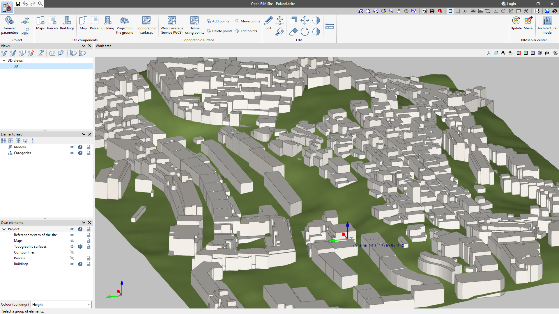
The Open BIM Site interface has been designed to make it easier to define the different aspects that describe the project site.
To this end, it has several accessible and intuitive tools, as well as a 3D workspace where realistic modelling of the environment can be carried out.
The following groups of options for modelling the project site can be found in the application toolbar: project, site components, topographic surface area, editing and BIMserver.center.
In the bar on the left-hand side of the application's workspace, users can find the model views and the tools for configuring them.
Under "Elements read", the projects imported from the BIMserver.center can be configured.
Under "Own elements", users can manage the visualisation options and snapshots of the project components.
Creating a new job and linking it to a project
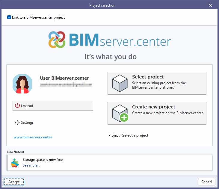
When launching the app and clicking on "New", users are given the option of creating a "New job", which can then be integrated into an existing project in BIMserver.center.
There is also the option to "Create new project". In this case, the created project will be visible from BIMserver.center from that moment on.
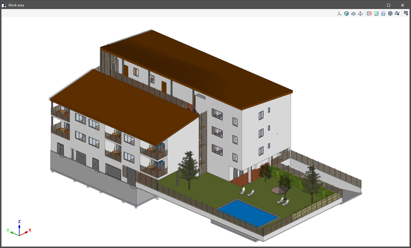
Once the new job has been created, users then access the interface, in which the graphic window showing the model or models that have been imported is displayed.
Users also have the option of starting the project without being linked to the BIMserver.center platform. To do this, simply uncheck the "Link to a BIMserver.center project" box in the top left-hand corner.
Files can be shared or imported at any time while the project is in progress via the BIMserver.center tab located at the top right of every program.
Importing BIM models
When creating a new job and selecting a project hosted on the BIMserver.center platform via "Select project", the "Import of BIM models" window appears, which shows the files contained in the project in IFC format.
The app offers users the option of including one or more of the existing models in the project. To do this, check the "Import" box and accept it.
When accessing the interface, the graphical window will display the imported models.

Template transformation
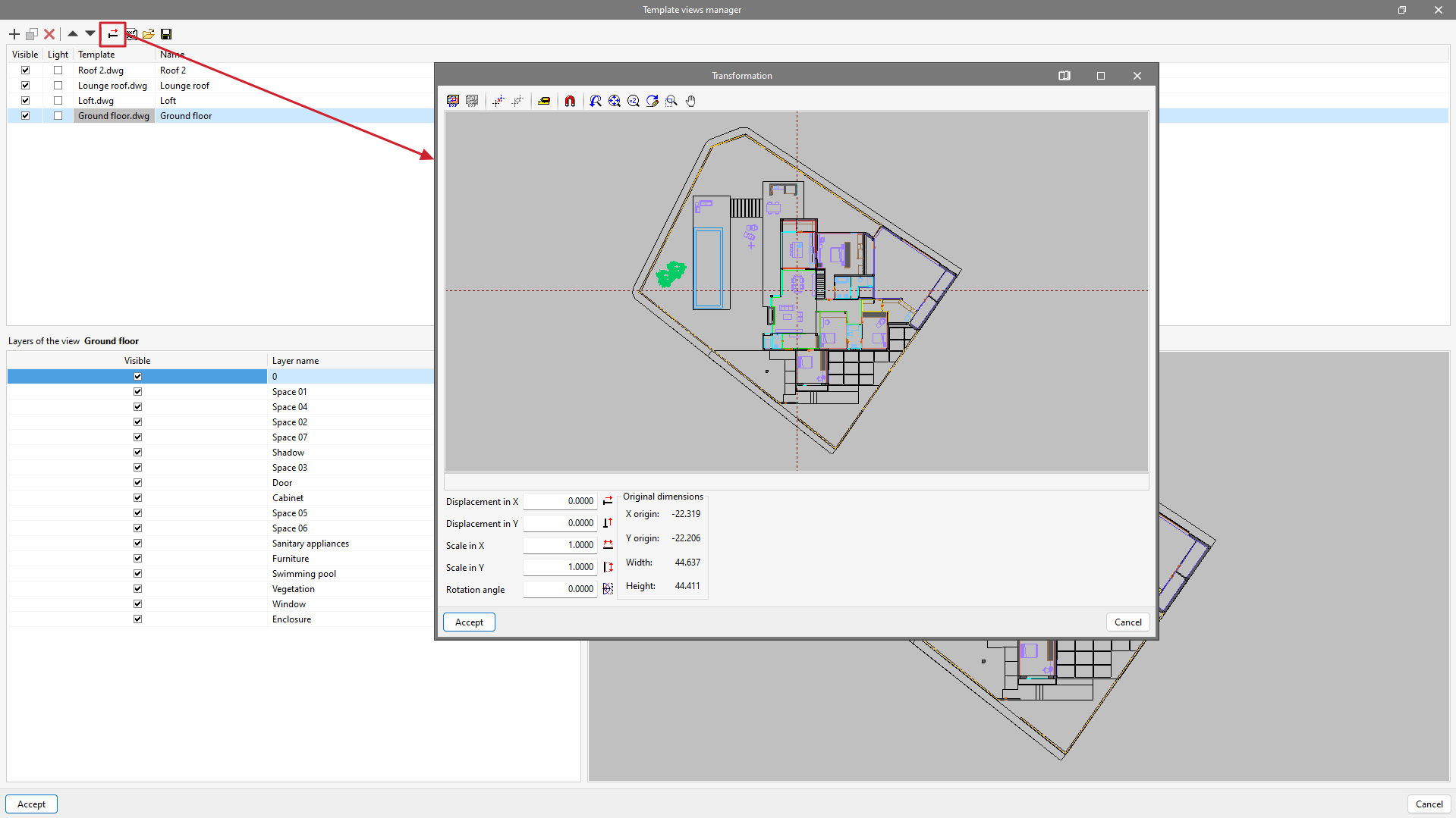
In "Template views manager", clicking on the tool with the red arrow will open a pop-up window called "Transformation", from which users can select the visible area of the template, apply a shift, rotate and/or change the scale, among others.
At the top of the window, we find a series of tools divided into groups:
- The first group allows users to "Select the visible area of the template" or restore the original area.
- The second group allows users to "Change the origin of the coordinates of a template" or reset it to the initial position.
- The third group, "Adjust the scale of a template", allows users to select two points on the template to create a segment with a known distance to adjust the scale of the template.
- The last group allows users to manage the visibility of the drawing view.
At the bottom of the window, we can enter numeric "Displacement" and "Scale" parameters on the "X" and "Y" axes or apply a "Rotation angle".
| More information: |
|---|
| The template transformation tool is very useful when different templates have to be imported from a single file. The drawings of a building are often grouped in a single file instead of being separated (per floor) in separate files. From the "Template views manager" window, the file containing the construction drawings must be added to the list and incorporated as many times as there are floors in the building. Once the floors have been correctly renamed, each template can be transformed by selecting the visible area for each floor and changing the coordinate origin to a common (or easily identifiable) element in all of them. Lift shafts, staircases, columns, etc. are recommended as a reference. |
Origin of the site reference system

General parameter settings
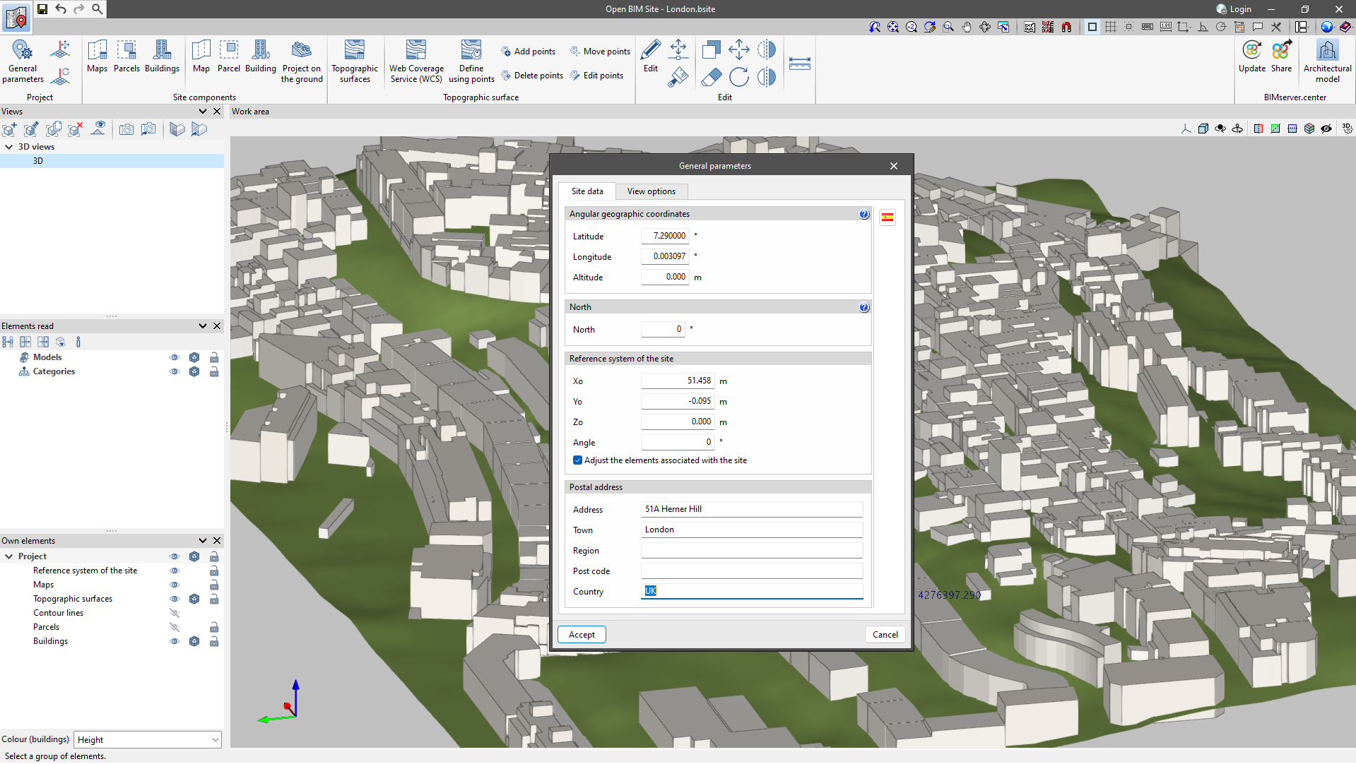
In the "Project" group there is a "General parameters" section, where the geographical location and site data can be entered.
- Angular geographic coordinates
In this section, users can enter the latitude, longitude and altitude of the site. The angular geographic coordinates allow the real location of the model to be defined. This information can be used for natural lighting calculations or the project's energy analysis. - North
The "North" direction is defined by the value of the angle relative to the positive y-axis of the project, in a counter-clockwise direction. The building orientation can be used for natural lighting calculations or the project's energy analysis. - Reference system of the site
Indicates the coordinate position of the project site. The location of the site coordinate system is usually expressed in UTM (Universal Transverse Mercator) coordinates. - Postal address
This section provides the address details of the site.
Moving and rotating the origin of the site reference system
With these tools, users can graphically redefine the origin and orientation of the site's reference system.
- Move the reference system of the site
Allows a new position for the origin of the site reference system to be defined on the work area. - Rotate the reference system of the site
Allows users to specify an angle on the work area to rotate the site reference system.
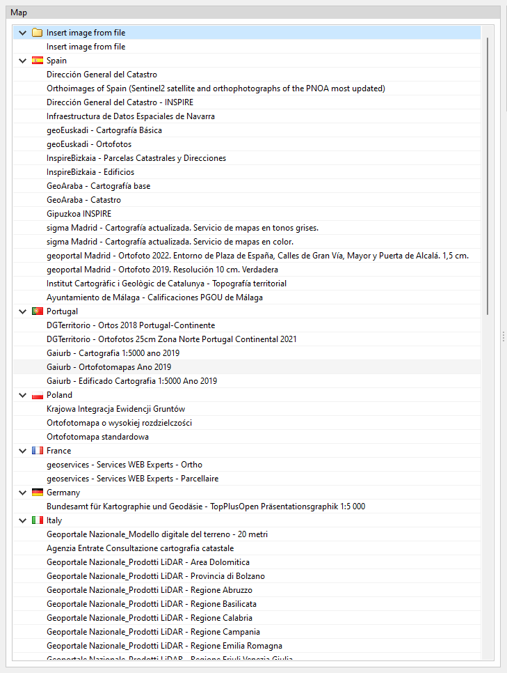
Connection to national web services
As well as DXF, DWG, JPEG, BMP, PNG, WMF, EMF, PCX and PDF files that can be imported from the application's template manager, it is also possible to access WMS web services to obtain spatially referenced maps.
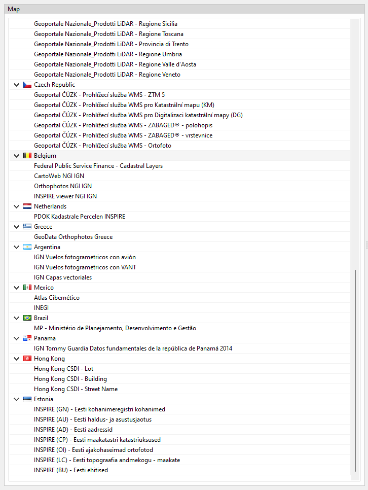
For projects in the following locations, a connection to national web services can be included to facilitate the input of site data, as well as the retrieval of maps and topographic surfaces.
- Spain
- Sede Electrónica del Catastro
- Instituto Geográfico Nacional
- Infraestructura de Datos Espaciales de Navarra
- Madrid (España)
- sigma Madrid - Cartografía actualizada. Servicio de mapas en tonos grises.
- sigma Madrid - Cartografía actualizada. Servicio de mapas en color.
- geoportal Madrid - Ortofoto 2022. Entorno de Plaza de España, Calles de Gran Vía, Mayor y Puerta de Alcalá. 1,5 cm.
- geoportal Madrid - Ortofoto 2019. Resolución 10 cm. Verdadera
- geoEuskadi – Cartografía Básica
- geoEuskadi – Ortofotos
- InspireBizkaia - Parcelas Catastrales y Direcciones
- InspireBizkaia - Edificios
- GeoAraba - Cartografía base
- GeoAraba - Catastro
- Gipuzkoa INSPIRE
- Ayuntamiento de Málaga - Calificaciones PGOU de Málaga
- Italy
- Geoportale Nazionale_Modello digitale del terreno - 20 metri
- Agenzia Entrate Consultazione cartografia catastale
- Geoportale Nazionale_Prodotti LiDAR - Area Dolomitica
- Geoportale Nazionale_Prodotti LiDAR - Provincia di Bolzano
- Geoportale Nazionale_Prodotti LiDAR - Regione Abruzzo
- Geoportale Nazionale_Prodotti LiDAR - Regione Basilicata
- Geoportale Nazionale_Prodotti LiDAR - Regione Calabria
- Geoportale Nazionale_Prodotti LiDAR - Regione Campania
- Geoportale Nazionale_Prodotti LiDAR - Regione Emilia Romagna
- Geoportale Nazionale_Prodotti LiDAR - Regione Friuli Venezia Giulia
- Geoportale Nazionale_Prodotti LiDAR - Regione Lazio
- Geoportale Nazionale_Prodotti LiDAR - Regione Liguria
- Geoportale Nazionale_Prodotti LiDAR - Regione Lombardia
- Geoportale Nazionale_Prodotti LiDAR - Regione Marche
- Geoportale Nazionale_Prodotti LiDAR - Regione Molise
- Geoportale Nazionale_Prodotti LiDAR - Regione Piemonte
- Geoportale Nazionale_Prodotti LiDAR - Regione Puglia
- Geoportale Nazionale_Prodotti LiDAR - Regione Sardegna
- Geoportale Nazionale_Prodotti LiDAR - Regione Sicilia
- Geoportale Nazionale_Prodotti LiDAR - Regione Toscana
- Geoportale Nazionale_Prodotti LiDAR - Provincia di Trento
- Geoportale Nazionale_Prodotti LiDAR - Regione Umbria
- Geoportale Nazionale_Prodotti LiDAR - Regione Valle d'Aosta
- Geoportale Nazionale_Prodotti LiDAR - Regione Veneto
- Panama
- IGN Tommy Guardia Datos fundamentales de la República de Panamá 2014
- Hong Kong
- Hong Kong CSDI - Lot
- Hong Kong CSDI - Building
- Hong Kong CSDI - Street Name
- Portugal
- Direção-Geral do Território. Divisão de Informação Geográfica
- DGTerritorio - Ortofotos 25cm Zona Norte Portugal Continental 2021
- Gaiurb - Cartografia 1:5000 Ano 2019
- Gaiurb - Ortofotomapas Ano 2019
- Gaiurb - Edificado Cartografia 1:5000 Ano 2019
- Poland
- Krajowa Integracja Ewidencji Gruntów
- Ortofotomapa o wysokiej rozdzielczośc
- Ortofotomapa standardowa
- France
- Geoservices - Services WEB Experts - Ortho
- Geoservices - Services WEB Experts - Parcellaire
- Germany
- Bundesamt für Kartographie und Geodäsie - TopPlusOpen
- Präsentationsgraphik 1:5 000
- Czech Republic
- Geoportal ČÚZK - Prohlížecí služba WMS - ZTM 5
- Geoportal ČÚZK - Prohlížecí služba WMS pro Katastrální mapu (KM)
- Geoportal ČÚZK - Prohlížecí služba WMS pro Digitalizaci katastrální mapy (DG)
- Geoportal ČÚZK - Prohlížecí služba WMS - ZABAGED® - polohopis
- Geoportal ČÚZK - Prohlížecí služba WMS - ZABAGED® - vrstevnice
- Geoportal ČÚZK - Prohlížecí služba WMS - Ortofoto
- Belgium
- Federal Public Service Finance - Cadastral Layers
- CartoWeb NGI IGN
- Orthophotos NGI IGN
- INSPIRE viewer NGI IGN
- Netherlands
- PDOK Kadastrale Percelen INSPIRE
- Greece
- GeoData Orthophotos Greece
- Argentina
- IGN Vuelos fotogrametricos con avión
- IGN Vuelos fotogrametricos con VANT
- IGN Capas vectoriales
- Mexico
- Atlas Cibernético
- INEGI
- Brazil
- MP - Ministério de Planejamento, Desenvolvimento e Gestão
- Estonia
- INSPIRE (GN) - Eesti kohanimeregistri kohanimed
- INSPIRE (AU) - Eesti haldus- ja asustusjaotus
- INSPIRE (AD) - Eesti aadressid
- INSPIRE (CP) - Eesti maakatastri katastriüksused
- INSPIRE (OI) - Eesti ajakohaseimad ortofotod
- INSPIRE (LC) - Eesti topograafia andmekogu – maakate
- INSPIRE (BU) - Eesti ehitised
Entering site components
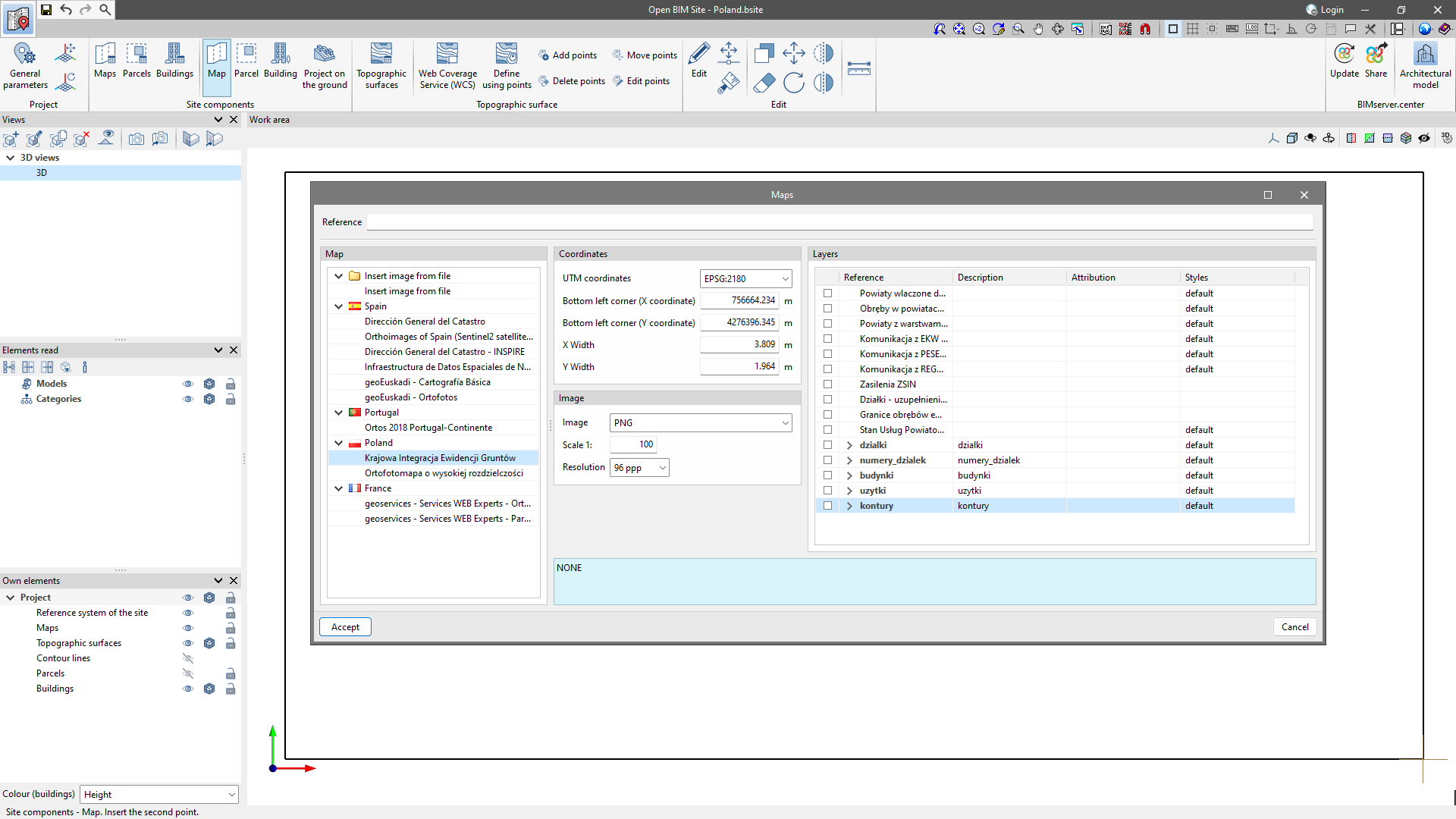
Entering maps

To insert maps, simply make a selection in the "Work area". Subsequently, the "Maps" window will appear, where it is possible to select different data sources to obtain the maps. The desired map can be configured in the following sections.
- Coordinates
Specifies the section of the space covered by the WMS service to be imported.
- Image
Allows users to configure the properties of the image to be downloaded.
- Layers
Some WMS services allow users to configure the layers of information that are added to the image.
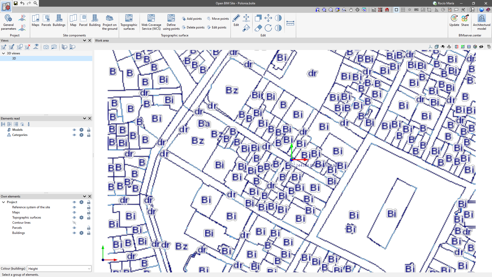
Entering parcels and buildings

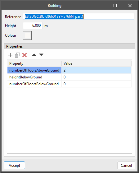
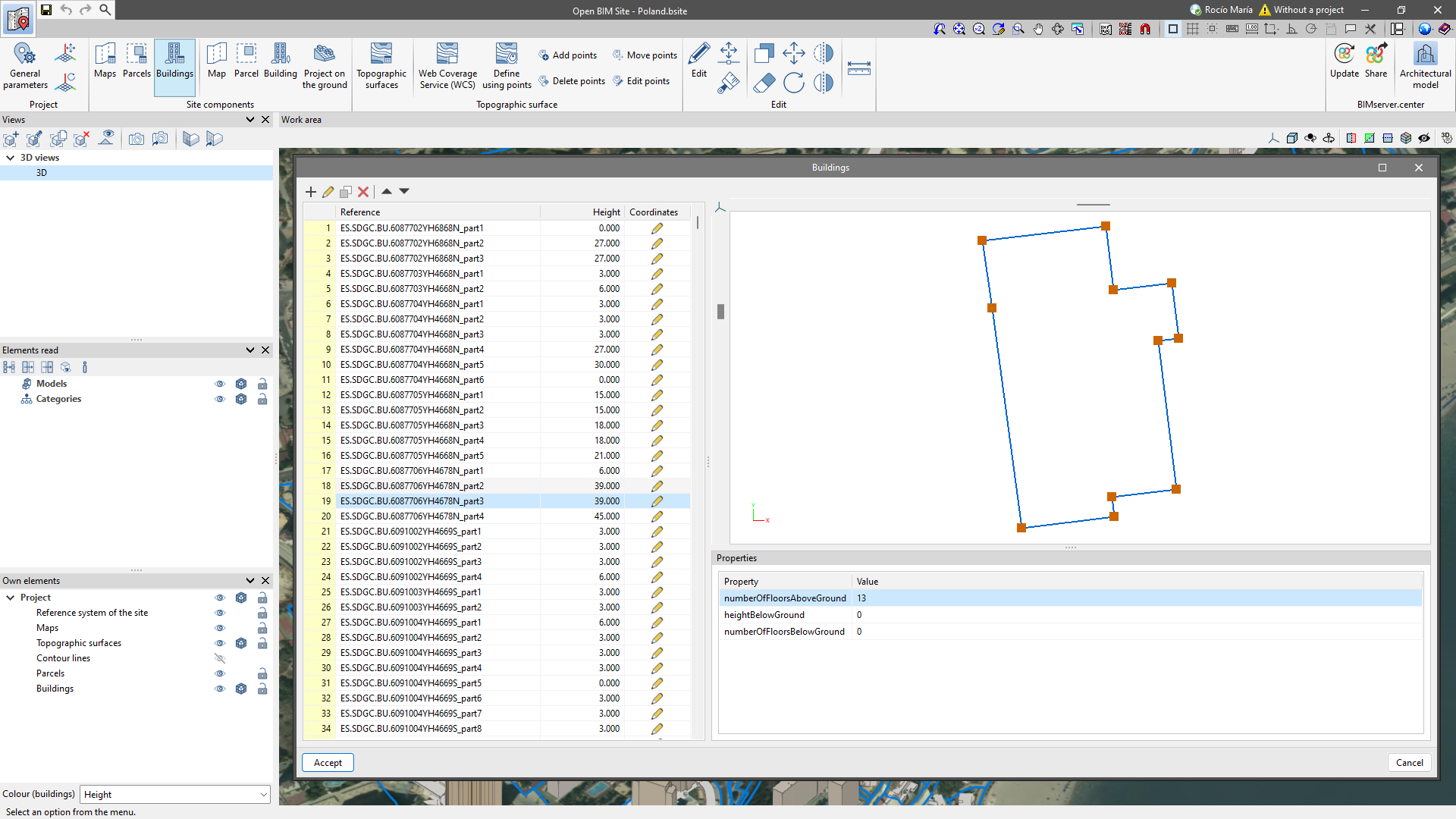
In Open BIM Site, users can define parcels by entering 3D contours. A parcel can contain buildings, which are defined not only by contour but also by height.
Both parcels and buildings can have associated properties for further information.
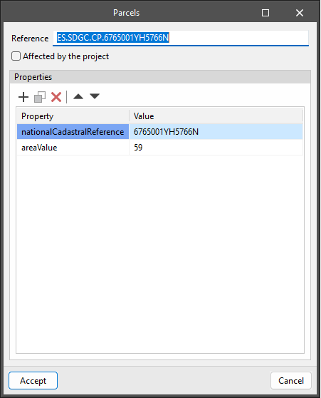
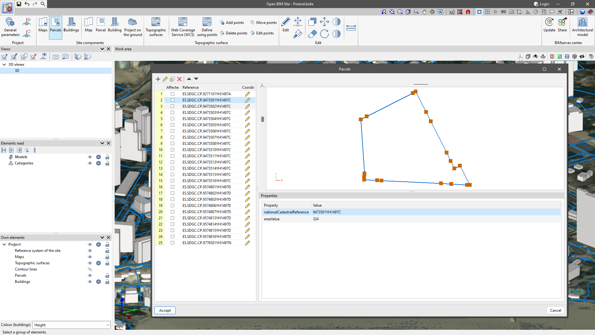
Furthermore, users can also specify on which parcels of the site model the project is to be implemented. In the "Parcel" configuration panel, there is the "Affected by project" option. When this option is activated, the outline of the parcel will be represented in a different colour in the work area.
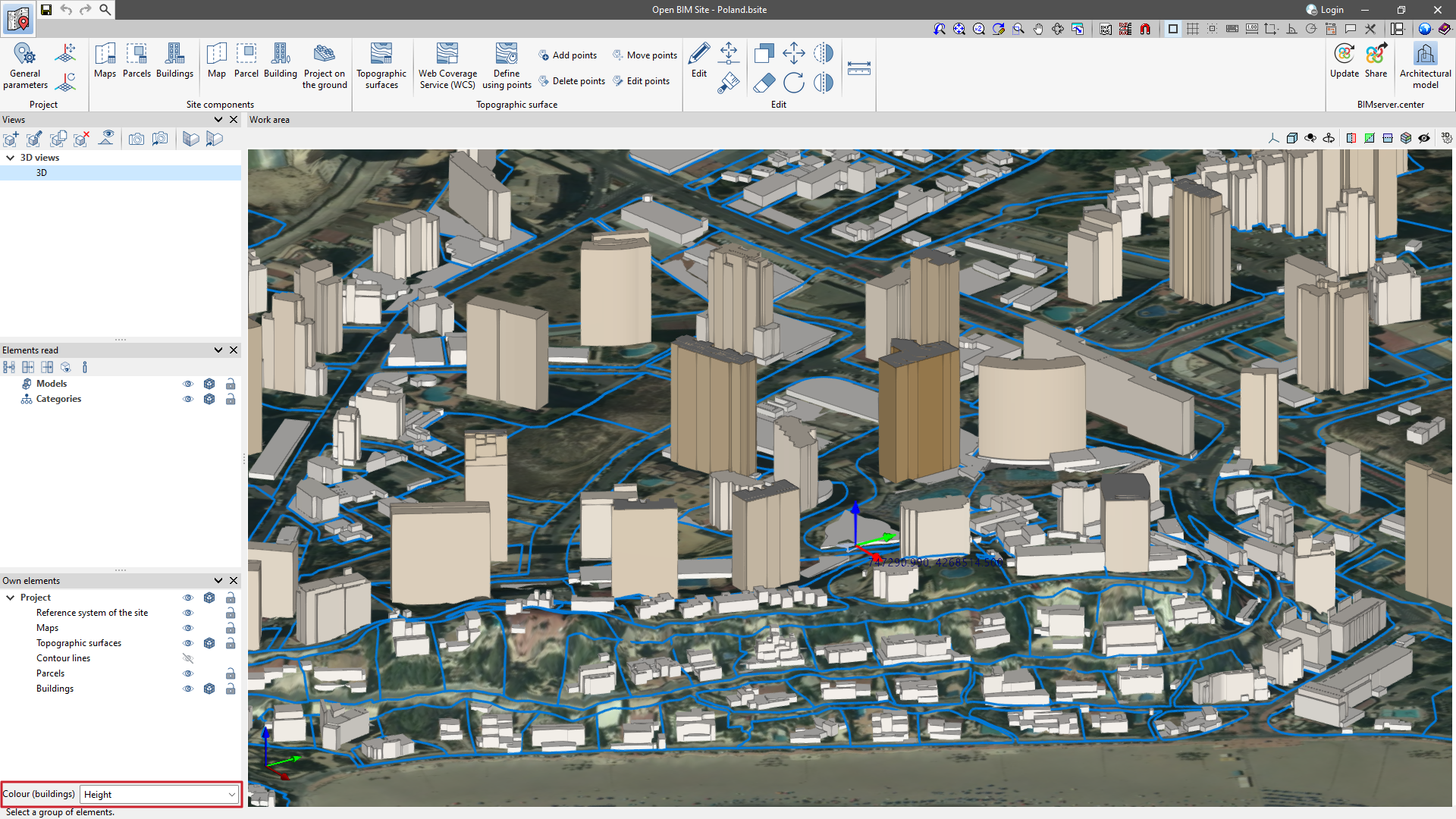
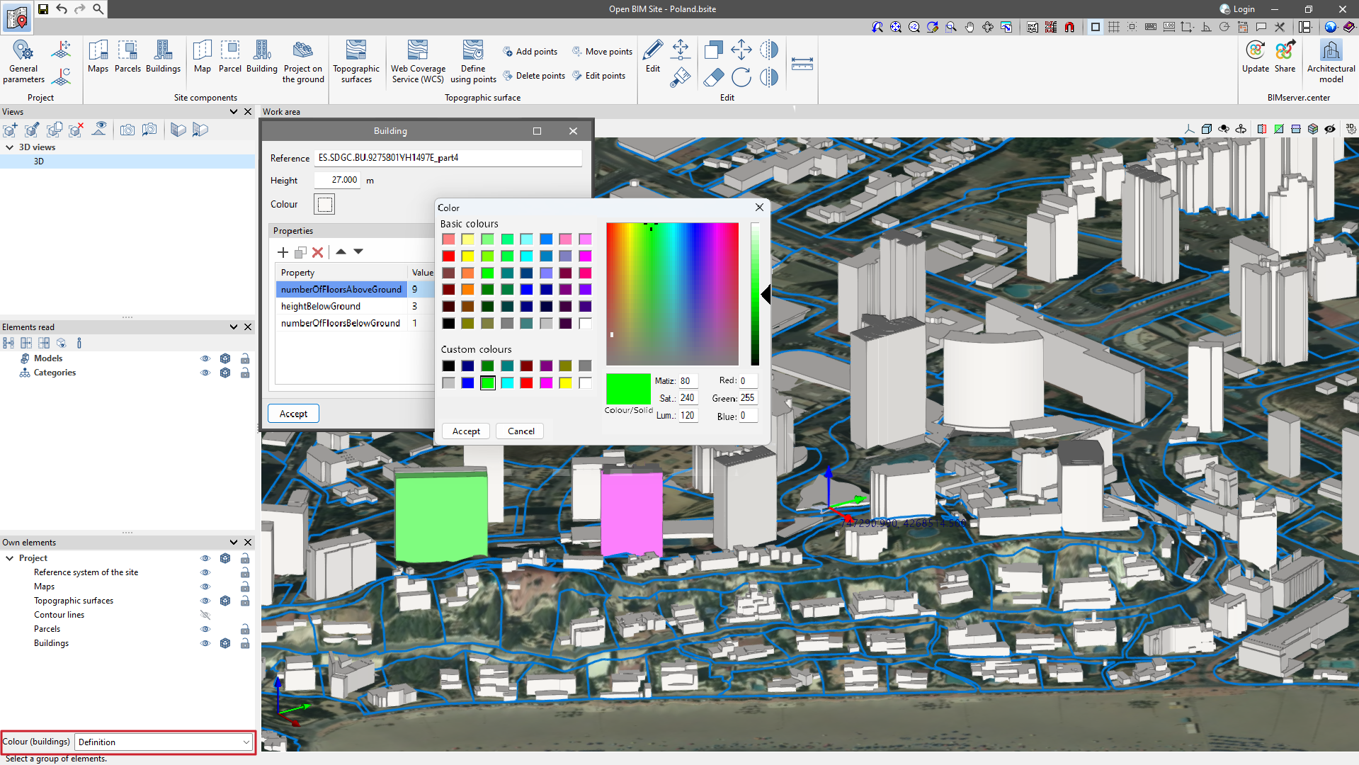
The buildings of the site model can be assigned a colour. The "Colour" parameter can be found in the "Building" configuration panel. Additionally, from the drop-down menu "Colour (buildings)" in the sidebar on the left-hand side of the drawing space, users can change how the colour of the buildings is displayed. This menu has the following options:
- Height
With this option, buildings are displayed in different colours depending on their height. - Definition
With this option, the buildings are displayed in the colour defined in their configuration panel.
Managing the site components

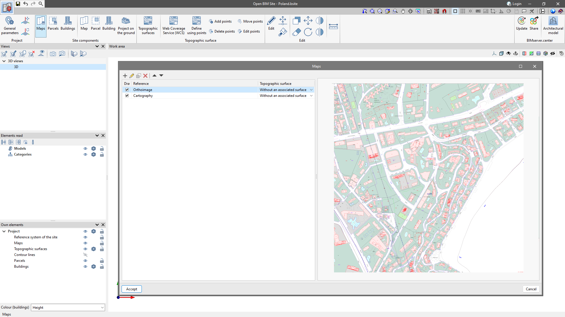
In the "Site components" group, the following options are available: "Maps", "Plots" and "Buildings" to manage the elements entered in the "Work area".
In the three windows for managing the components, users can "Add" a new component, "Edit" an existing element, generate an identical component using "Copy", and "Delete" to delete the selected element, as well as use arrows to sort the elements in the table.
In the "Maps" section, users can control the individual visibility of each map via the "Draw" column, where the checkbox for displaying the map in the "Work area" can be activated. A previously created topographic surface can also be associated with the map.
In the "Buildings" and "Parcels" sections, users can edit the coordinates of the individual points. Additionally, in the "Parcel" window, the checkbox of the parcel that is "Affected by the project" can be activated.
Topographic surfaces
Topographic surfaces allow the topography of the site to be represented.
In Open BIM Site, users can easily enter topographic surfaces into the model from the following sources:
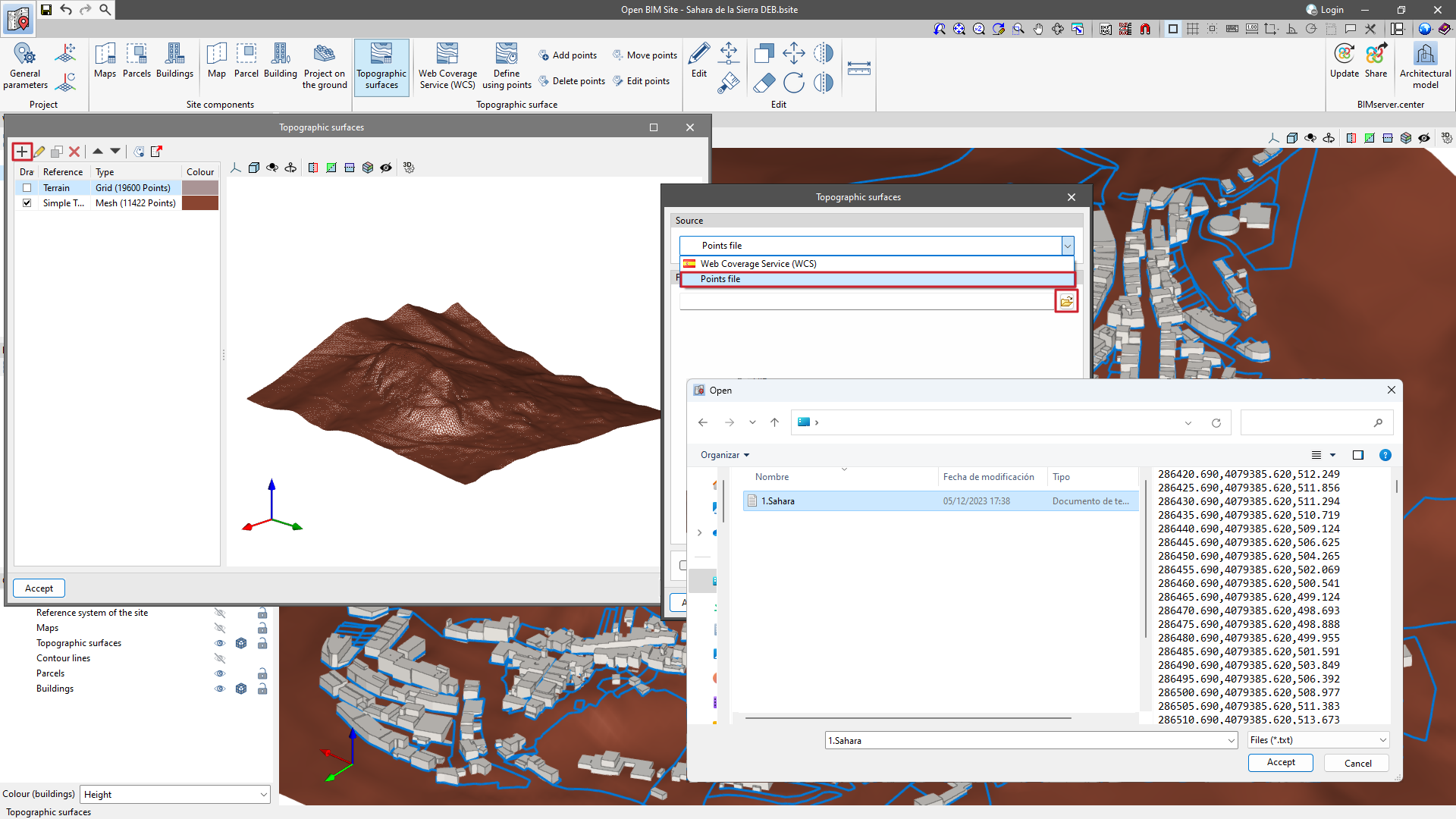
Creating topographic surfaces by points files
Topographic surfaces can be defined using a points file.
Open BIM Site can read points files in Esri ASCII format (ARC/INFO) and comma-separated value files (CSV or TXT).
To enter a points file, click on the "Topographic surfaces" option and add an element to the list. In the pop-up window, select the "Points file" option and search for the file on the hard disk.
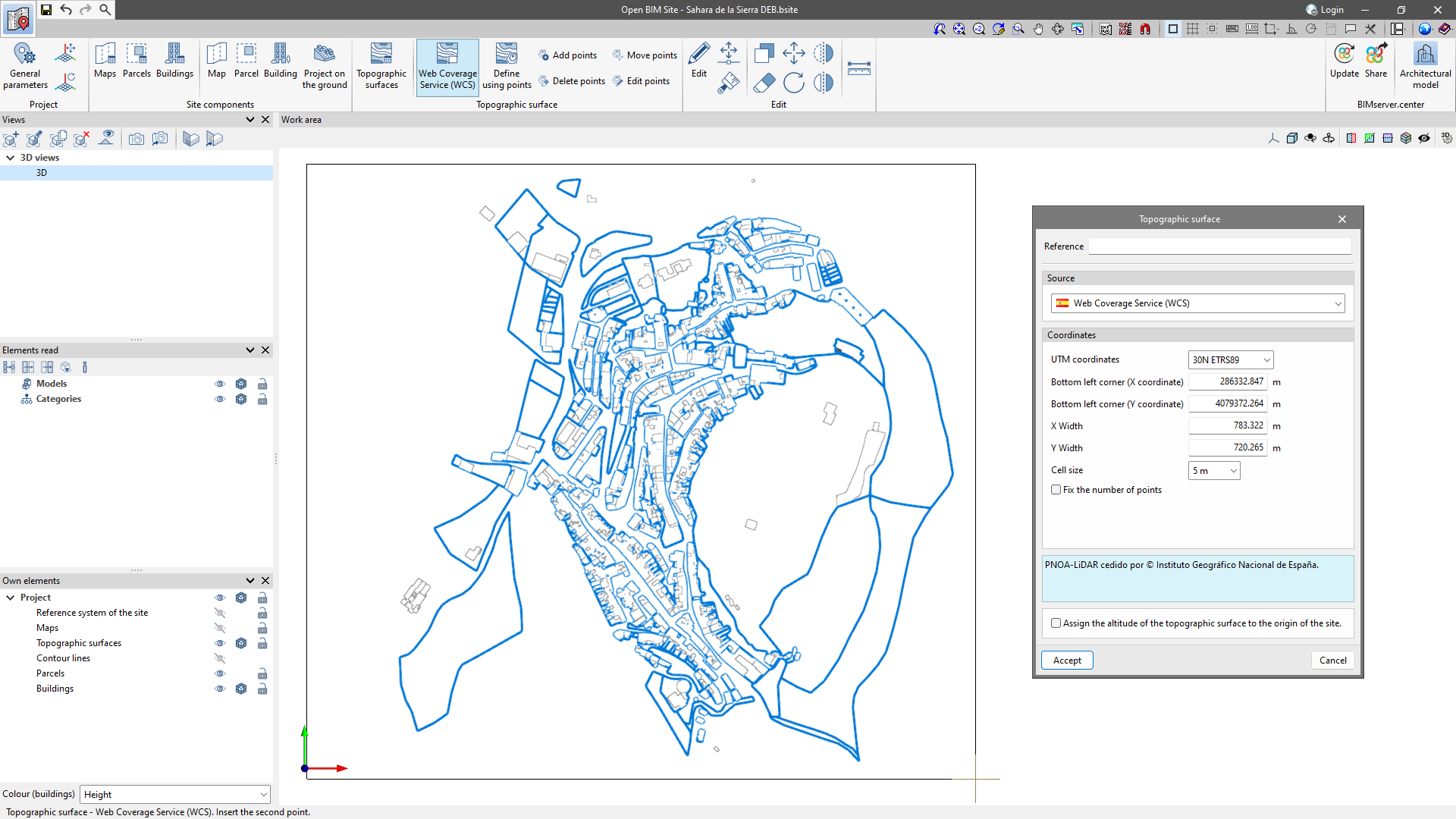
Creating topographic surfaces by Web Coverage Service (WCS)

Digital terrain models (DTM) from airborne LiDAR sensors of the PNOA-LiDAR project of the Cartographic System are obtained through the web service.
To import the topographic surfaces via WCS, click on the "Web Coverage Service" option and enter two points in the "Work area", corresponding to the diagonal corners of the rectangle that encloses the topographic surface.
In the pop-up window, the following data will be filled in automatically and can be modified as desired:
- UTM coordinates;
- Bottom left corner (X coordinate);
- Bottom left corner (Y coordinate);
- X width;
- Y width;
- Cell size;
- Fix the number of points.
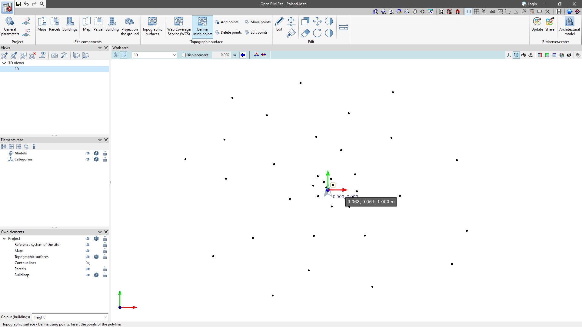
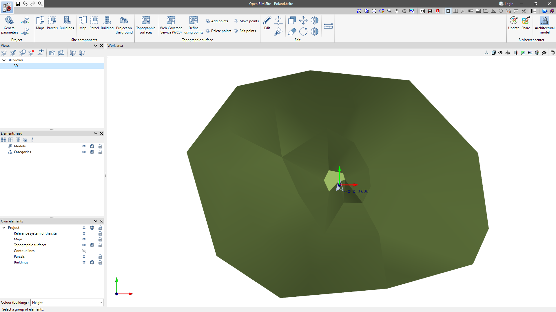
Creating topographic surfaces by points

The Open BIM Site program also allows users to enter a topographic surface by placing topographic points on the work area. To do this, the "Define by points" option is found in the "Topographic surface" group, which is available in the application’s toolbar.
Once the points have been entered, the application will automatically generate the ground and add it to the list of topographic surfaces in the project.
Editing the points of a topographic surface

The points that make up the topographic surfaces of the project can be modified. To do this, the following options are available:
 Add points
With this tool, users can select an existing topographic surface and add new points to its configuration.- Delete points
Allows users to delete one or more points belonging to the topographic surfaces of the model. - Move points
Allows users to edit the position of one or more points belonging to the topographic surfaces of the model. - Edit points
Allows users to edit the elevation of one or more points belonging to the topographic surfaces of the model.
Simplifying a topographic surface
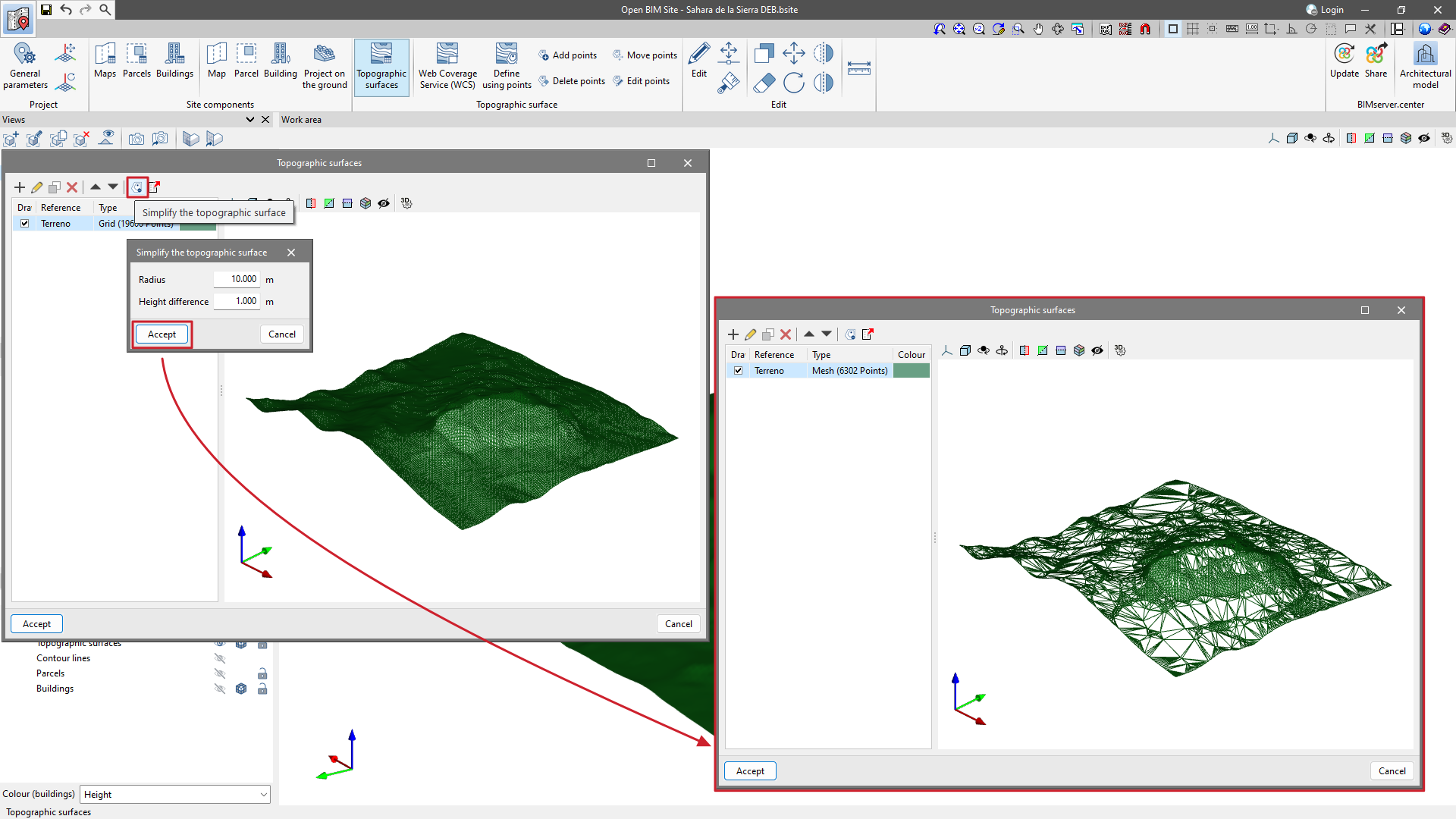
From the "Simplify the topographic surface" option available in the "Topographic surfaces" management window, users can simplify the number of points contained in the topographic surfaces and, in this way, increase the application's performance.
Once the simplification process has been completed, users may want to review the result and increase its accuracy by editing the topographic points if necessary.
Contour lines
In the field of topography, contour lines are lines that connect points with identical altitudes on a map. This makes it possible to easily identify areas with different degrees of elevation change.
The generation of contour lines in Open BIM Site is automatic. However, their display on the 3D model can be controlled from "Own elements".
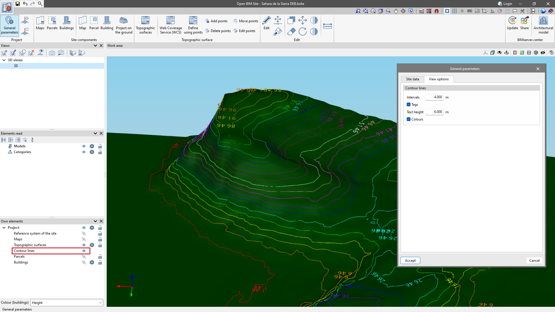
From the "General parameters" section, available in the "Project" group, there is a tab called "Display options". From here, users can configure the display of the contour lines with the following parameters:
- Intervals
Shows the vertical distance between two contour lines. - Tags
Activating this option will display a text next to the contour lines to show their elevation.- Text height: determines the text size of the tags.
- Text height: determines the text size of the tags.
- Colours
When this option is activated, a colour scale will be used to represent contour lines according to their elevation. Otherwise, the contour lines will be drawn in black.
Managing the topographic surfaces

In the "Topographic surface" section, the topographic surfaces entered in the "Work area" can be managed.
In the pop-up window are options for users to "Add" a new surface, "Edit" an existing one, generate an identical surface using "Copy," and "Delete" to remove a selected surface. There are also arrows for sorting the elements in the table. Also on this toolbar are options such as "Simplify the topographic surface" and "Export the topographic surface to a points file".
The individual visibility of each topographic surface can be controlled via the "Draw" column, where the check box for displaying the topographic surface in the "Work area" can be activated. In the "Type" column, users can specify whether the points of the topographic surface are represented by a mesh or a grid. Furthermore, a colour can be assigned to each topographic surface.
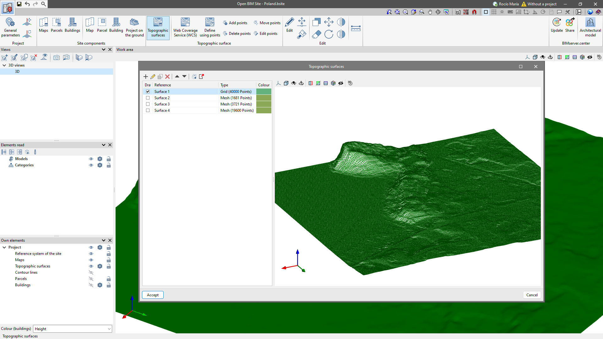
Finally, on the right-hand side, there is a 3D view of the topographic surface and a toolbar to control the visibility.
Projecting on topographic surfaces
Projecting maps on a topographic surface
In the "Maps" window, a topographic surface can be associated with each map.
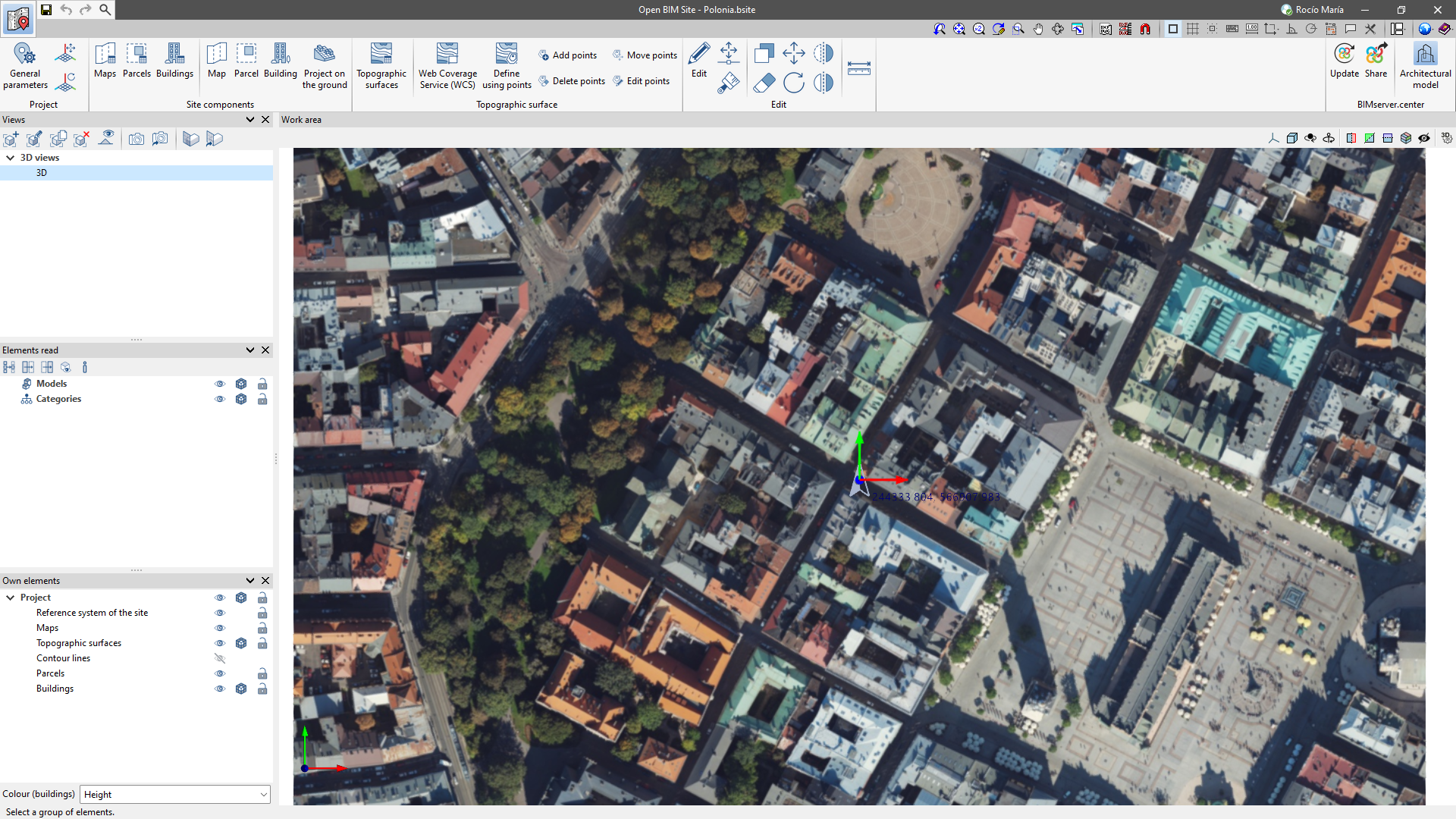
When associating the topographic surface, the map will be projected and displayed in the "Work area" with the elevation changes of the associated surface.
When selecting the "Without an associated surface" option, the map will be drawn at zero elevation.

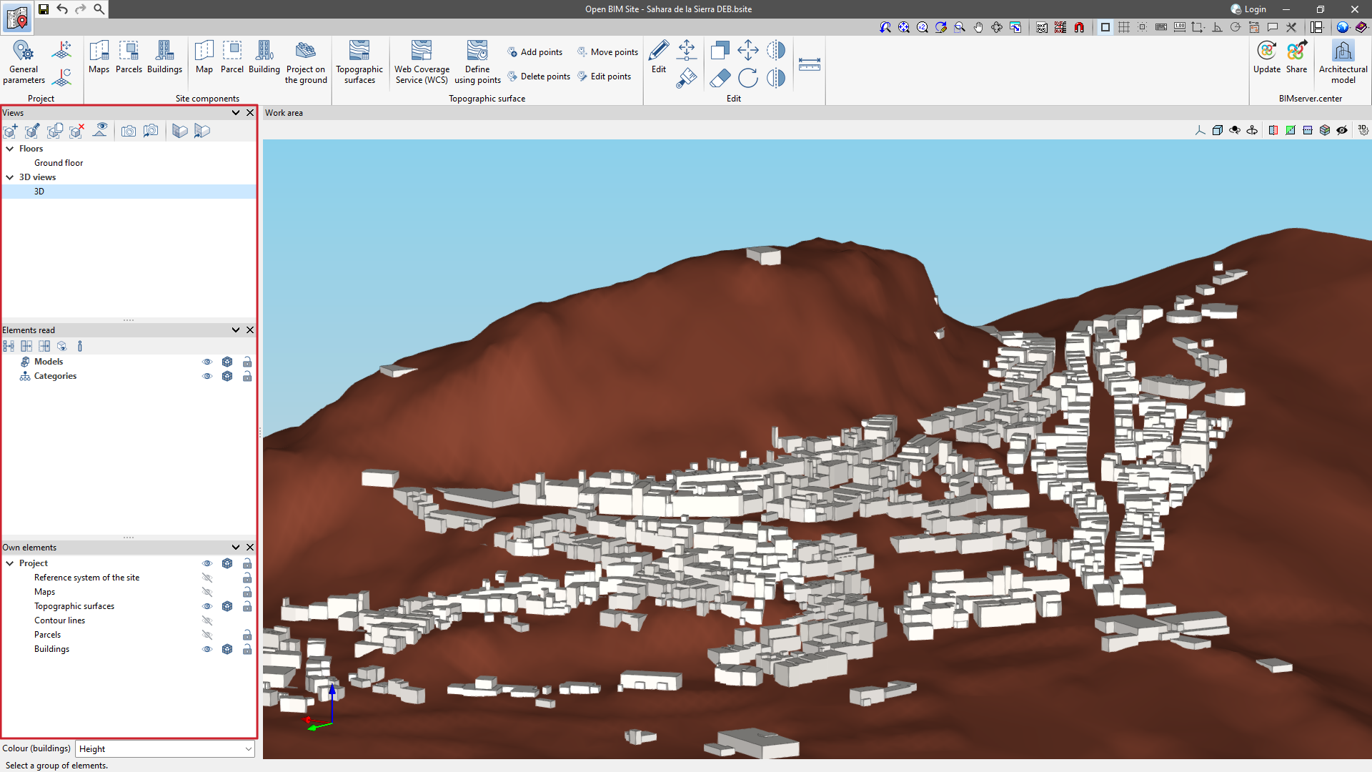
Projecting parcels and buildings on the ground

Once the topographic surfaces, plots and buildings have been entered, the contours of the plots and buildings can be projected onto the ground using the "Projection on the ground" option.
This provides a more detailed and contextualised perspective of the project location.
Editing tools

The following tools in the "Edit" group of the Open BIM Site program can be used on the maps and topographic surfaces of the project:
| Edit | Allows users to select an element and edit its parametric properties. | |
| Move | Allows users to move the "x", "y" and "z" coordinates of each point of the site components. | |
| Match | With this option, users can assign the characteristics of a building to other buildings on the same site. | |
| Copy | This option creates an identical copy of the selected element. | |
| Move a group of elements | Allows a selection of elements to be moved together. | |
| Symmetry (copy) | Allows the symmetry of the selected object to be carried out without deleting it. | |
| Symmetry (move) | Allows users to mirror the selected object by deleting it. | |
| Rotate a group of elements | Allows a selection of elements to be rotated together. | |
 | Delete | Works in the same way as the "Delete" key. |
| Measure | Allows distances to be measured by snapping points. |
Managing the visibility of the elements in a project
The visibility of the different elements required for the project site can be managed through three sections on the left-hand side of the program's main interface:
- Views
This option allows users to create, edit, save the start scene and return to the start scene. - Elements read
These are the elements exported from other disciplines. - Own elements
These are the elements created in the program itself.
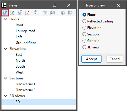
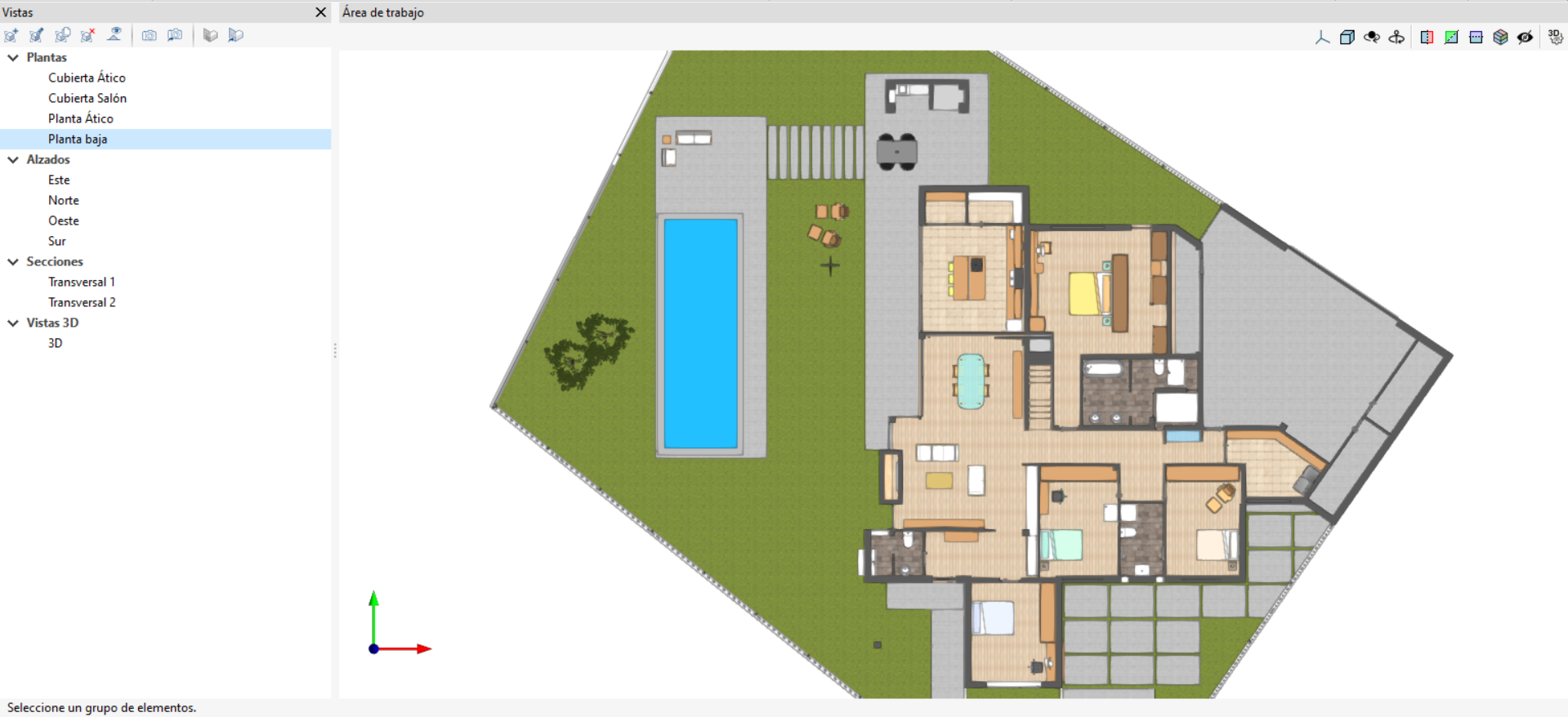
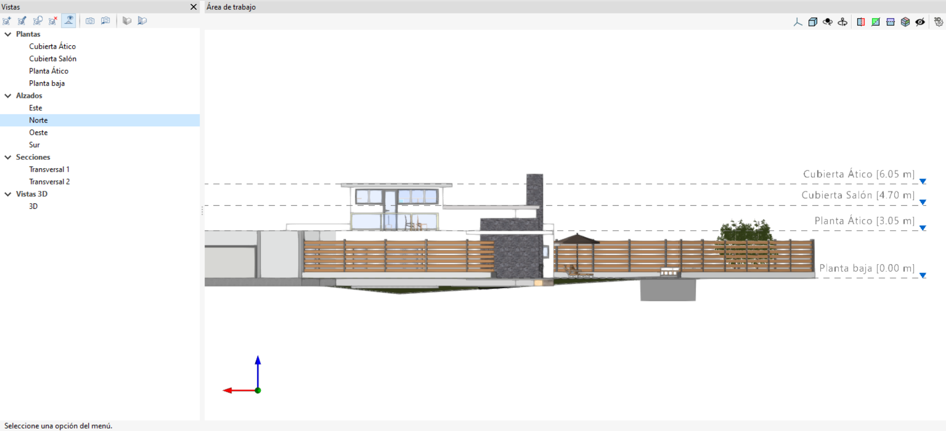
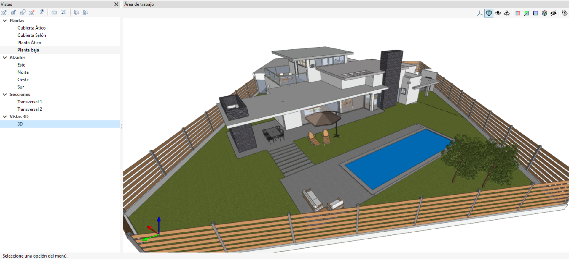
Managing views
Programs with the "Views" section can create different views to make navigation and the architectural modelling process easier. The following types can be created: plan, reflected ceiling, elevation, section, generic and 3D view.
The following options are also available in the top toolbar:
- Create
Creates a new 2D or 3D view of the model. - Edit
Modifies the properties of the current view. - Duplicate
Copies the current view. - Delete
Deletes the current view. - Show references
By selecting this option, references to other views will be displayed in the active view. - Save the start scene
Sets the current position of the view as the start scene. - Go to start scene
Sets the current view to the starting scene. - Define
Specifies the working plane associated with the current view. The work plane serves as the basis for the entry of the model components. - Go to the workplane
Aligns the current view with the position of the work plane.
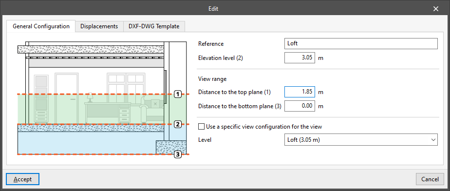
"General configuration" tab
When you "Edit" each view, you can adjust the following settings in the "General settings" tab:
- Reference
View reference. - Use a specific display configuration for the view (optional)
When this option is enabled, the text "View" will appear in the "Read elements" menu, and its settings will apply only to the selected view.
If this option remains disabled, the text "View" will not be displayed, and the "Read elements" settings for the entire project will be visible and can be adjusted.
The following fields are displayed in the floor plans:
- Elevation level
The elevation where the view is located, measured relative to the general horizontal XY plane. - Level
Select the level associated with the view. This ensures that this level is automatically applied to any elements added to that view, provided that automatic elevation detection is not used.
| Note: |
|---|
| Floors form an internal data structure within the building model, whilst floor plans are simply partial representations of the model on screen. |
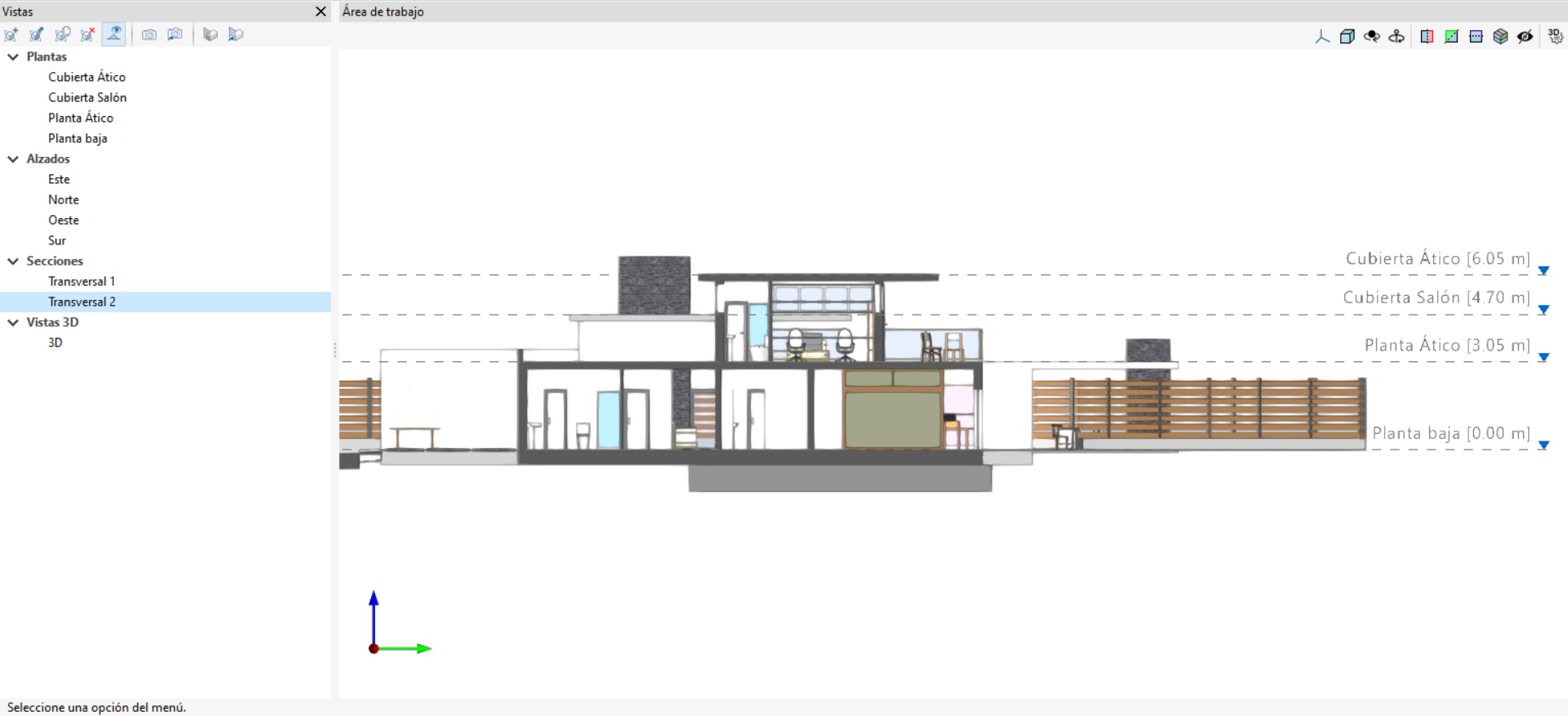
In the 2D views, the following section appears:
- View range
These values specify the distance to each of the planes from the view origin.
All view types, except for the 3D view, are associated with a region bounded by two planes, which determines which elements will be displayed within it.
For example, plan views will show the elements bounded and cropped by two planes situated at the specified "Distance to upper plane" and "Distance to lower plane", measured from the "Level dimension".
In elevation views, section views and generic views, the rear plane is the one perpendicular to the viewing direction in the positive direction. The front plane is the same, but in the negative direction.
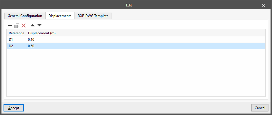
"Displacements" tab
In this tab, you can create and manage displacements associated with the view, which can be loaded and used when entering elements into the view using the relevant option.
These displacements are applied to the level or position dimension of the view plane.
"DXF-DWG Template" tab
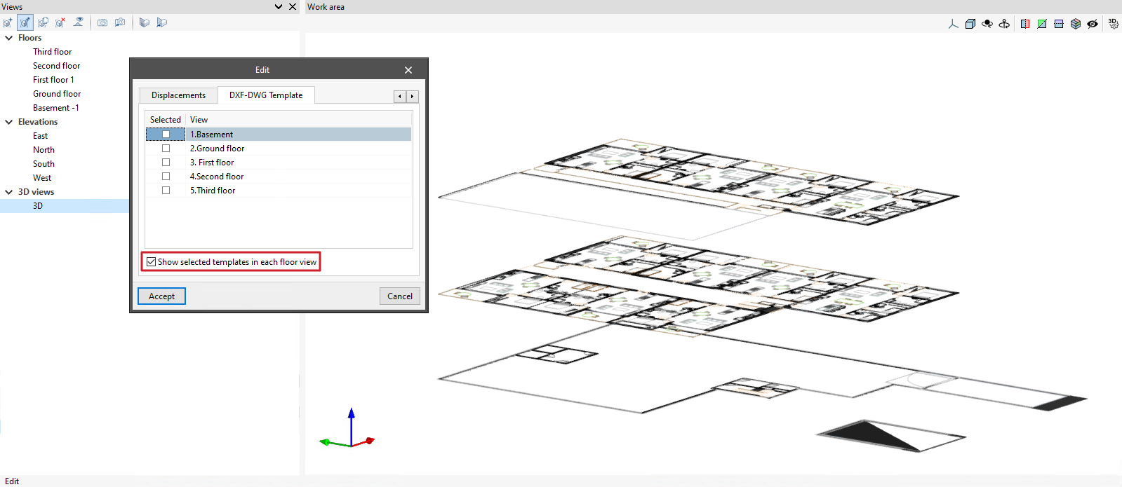
From the "Views" section, whilst creating or editing a view, you can manage the visibility of templates on the "DXF-DWF Template" tab.
This tab displays a report of all the templates imported into the project.
Ticking the box will display the template on the assigned floor plan.
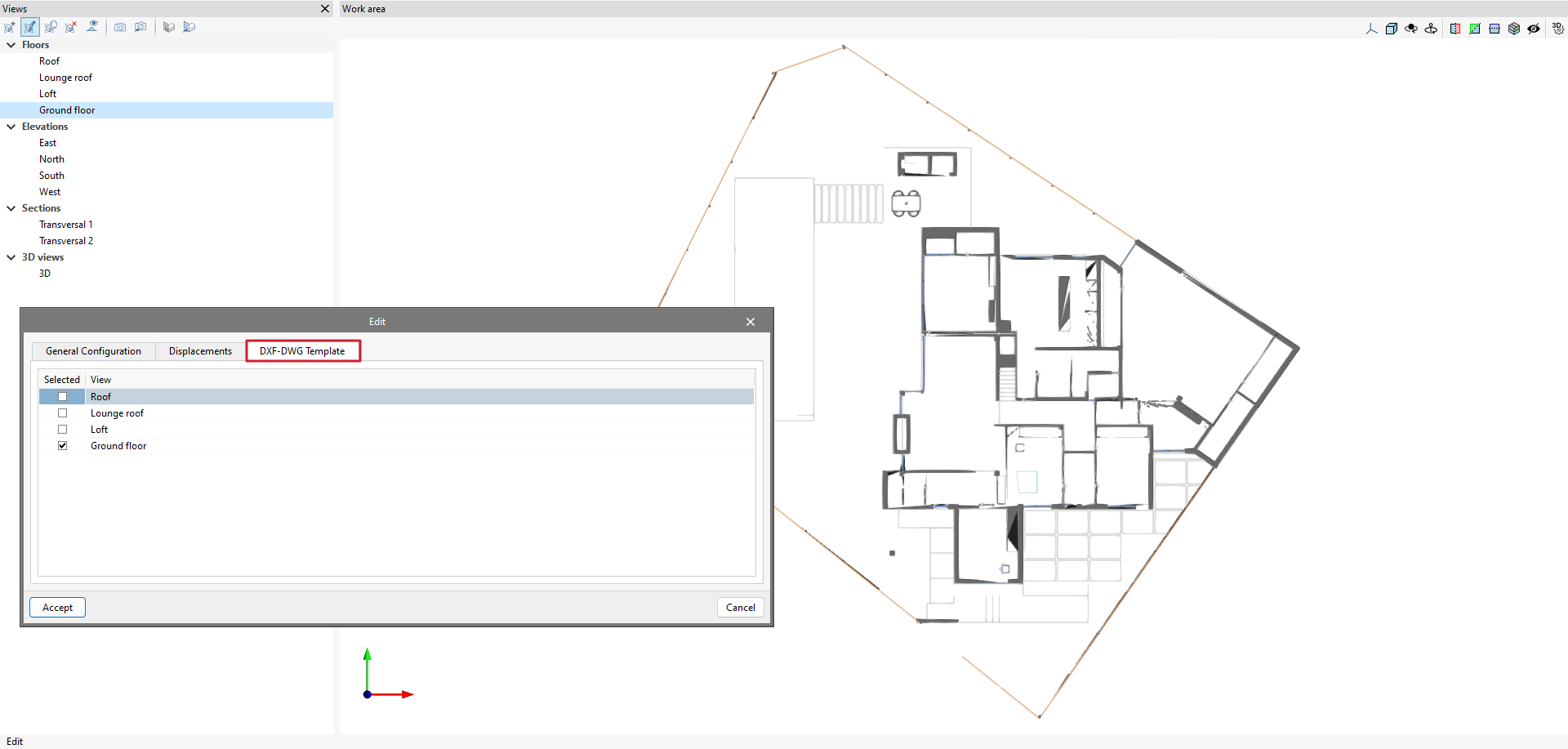
Furthermore, in 3D views, you can enable the "Show selected templates in each floor view" option.
When this option is ticked, the templates visible in each floor plan view will be displayed in the 3D view and at the corresponding dimension.
| More information: |
|---|
| The following link explains how to import DXF, DWG, PDF and JPG drawings into the project. |
Managing elements read
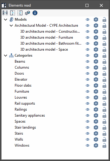
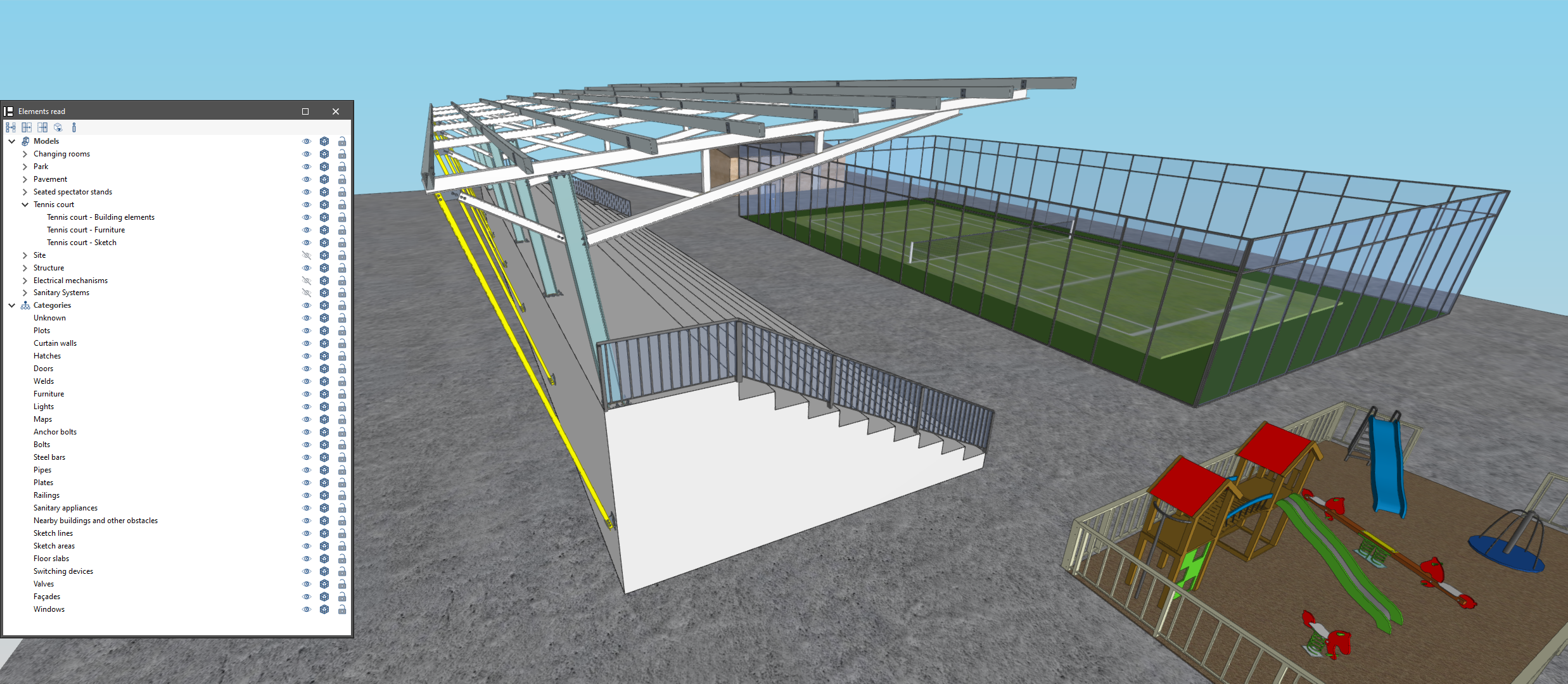
The management of the elements from the digital model of the building, obtained from the associated BIM project, is carried out from the "Elements read" menu located on the left sidebar in the app.
The elements read are structured in the form of a tree according to two types of classification:
- By "Models": users can inspect each contribution linked to the job and, within this, each associated 3D model.
- By "Categories": users can group the "Elements read" into families according to their characteristics.
Three buttons are displayed next to each component of the tree:
- Visible
Enable or disable the visibility of the elements. - Visualisation mode
Toggle between normal, transparent and wired display modes. - Snap
Enable or disable object snaps of the elements.
| Note: |
|---|
| Please note that the settings applied within the organisation using "Models" are prioritised over those specified using "Categories". |
The following actions can be carried out via the toolbar in the top left-hand corner:
- Isolate selection
Isolate elements of the 3D model. By selecting the elements of the 3D model to be isolated and clicking the right mouse button, the rest of the elements of the model will disappear. - Hide
Hide the selected elements. By selecting the elements of the 3D model to be hidden and right-clicking on them, they will disappear. - Show all
Show all hidden elements. - Appearance
Choose between normal drawing and monochrome drawing. - BIM information
Display a panel with the attributes associated with the selected component.
Settings by "View"
If the "Use a specific display setting for this view" option has been enabled in the active view, the text "View" will appear in the "Read elements" menu, and the settings defined will apply only to the selected view.
Otherwise, the general settings for the entire job will be displayed and applied.
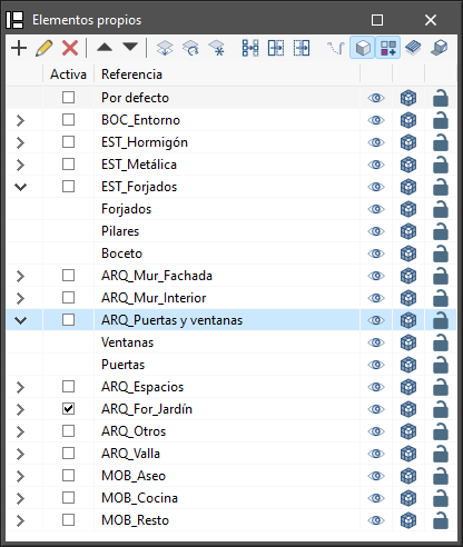
Own element management
In this section, the elements of the job opened by the program the user is working with are organised in layers that can be created, deleted, edited, sorted, shown or hidden according to their preferences. Within each layer, the elements can be displayed in grouped categories, which can be expanded or collapsed by clicking on the arrows on the left.
Depending on the program being used, the following options and controls appear next to each component of the tree:
- Visible
Enable or disable the visibility of the elements. - Visualisation mode
Choose between normal, transparent and wired display modes. - Snap
Activate or deactivate object snaps of the elements.
In the top toolbar, several options for managing layers can be found:
- Add
Create a new layer. - Edit
Edit the selected layer reference. - Delete
Delete the selected layer reference. - Move selected element up/down the list
Move the selected layer one place up or down in the list. - Assign layer (Ctrl + A)
This makes it easier to change the element from one layer to another. The program allows users to select the layer where the element is to be assigned. - Update layers
Regenerate the display of all layers and makes them visible. - Isolate layer
Isolates the active layer, hiding the other layers available in the project. - Isolate selection (Ctrl + I)
Select several elements to remain visible; those not selected will be hidden. - Hide elements (Ctrl + H)
Control the visibility of each element. - Show elements (Ctrl + U)
Undo the "Isolate selection" and "Hide elements" actions mentioned above.
Visibility monitoring tools to support the modelling
In the top right corner of the 3D viewing area is a toolbar that is used to control the visibility of the model during the modelling process.
This bar offers various options to make it easier to manage and visualise the project. Some of the options are shown in the following image.

The first section covers the options for controlling the display modes of the model:
- Projection
Opens a window that allows users to select predefined projections, such as top view, front view, isometric view, orthogonal view, etc. - Projection type
Modifies the type of projection from axonometric to conic and vice versa. - Rotation around a point
Activates or deactivates the rotation of the scene around a point of an object located under the cursor. - Rotation around the camera
Activates or deactivates the rotation of the scene around the vertical axis of the camera.
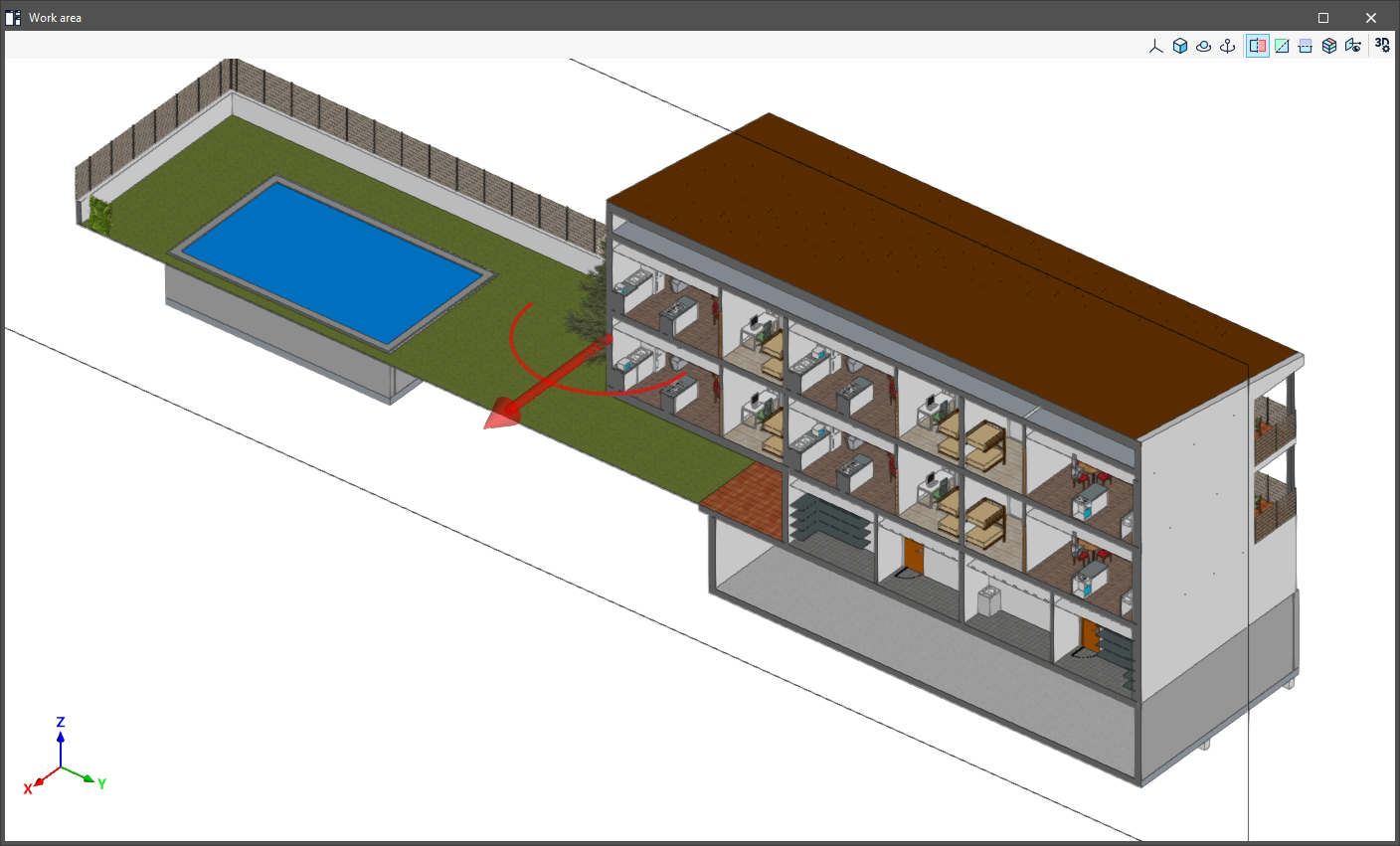
The following 5 options are used to create sections for viewing the BIM model from different perspectives and to create customised views.
- Section perpendicular to the global "X" axis
Defines a section of the model perpendicular to the global "X" axis. - Section perpendicular to the global "Y" axis
Defines a section of the model perpendicular to the global "Y" axis. - Section perpendicular to the global "Z" axis
Defines a section of the model perpendicular to the global "Z" axis. - Clip volume
Defines a display volume using 6 cutting planes that is formed from the geometric envelope of the scene content. - Show/Hide section planes
Manages the visibility of the lines and symbols of the sections created.- You can move and reposition each section plane by clicking and dragging the arrow icon that defines it.
- To rotate each section plane, click and drag the curved arc symbol next to the arrow.
- You can also flip the orientation of each section plane by double-clicking the arrow icon.
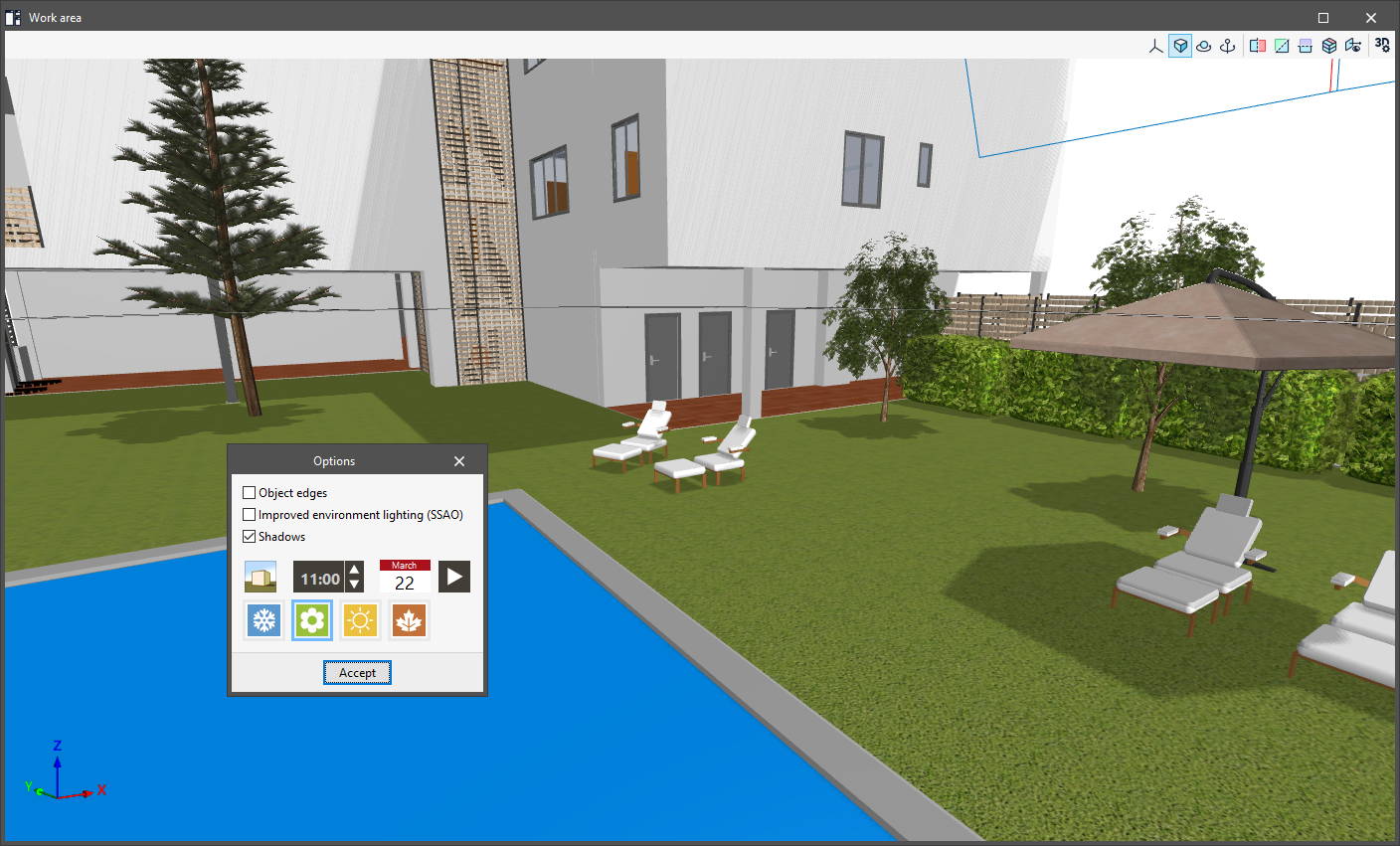
The last option opens the "Options" panel, which contains the following tools:
- Object edges (optional)
Enable or disable the display of object edges in the scene. - Enhanced ambient lighting (SSAO) (optional)
Enable or disable enhanced ambient lighting in the scene. - Shadows (optional)
If this option is enabled, the program simulates the sun's path across the site throughout the year, making it possible to assess the impact of surrounding shading cast by both the building itself and nearby buildings and other obstructions.- Display
Display the position of the sun on the selected day and at the selected time, as well as the path or positions of the sun throughout the year. - Time
Select the solar time. - Date
Select the date. - Animation
Display an animation of the shadows cast throughout the year at the selected time. Pressing this button again stops the animation. - Winter / Spring / Summer / Autumn
These options are shortcuts that allow you to load the first day of each season directly.
- Display
Results output
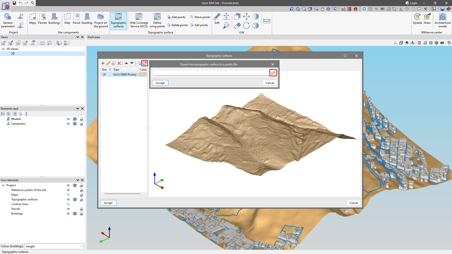
Exporting a topographic surface to a points file
From the "Topographic surfaces" section of the project, in the top toolbar is the "Export surface to a point file" option.
The output format is a comma-delimited value file with the "x", "y", "z" coordinates of each point on each line.
Integration into the BIMserver.center platform
Many of CYPE's programs are connected to the BIMserver.center platform and allow collaborative work to be carried out via the exchange of files in formats based on open standards.
Please note that, to work on BIMserver.center, users can register on the platform free of charge and create a profile.
When accessing a program connected to the platform, the program connects to a project in BIMserver.center. This way, the files of the projects that have been developed collaboratively in BIMserver.center are kept up to date.

| More information: |
|---|
| For further details related to using CYPE software via the BIMserver.center platform, please click on this link. |
Options available in Open BIM Site

In the top right corner of the main toolbar are the tools needed to use Open BIM Site and other BIMserver.center tools.
Importing and updating BIM models
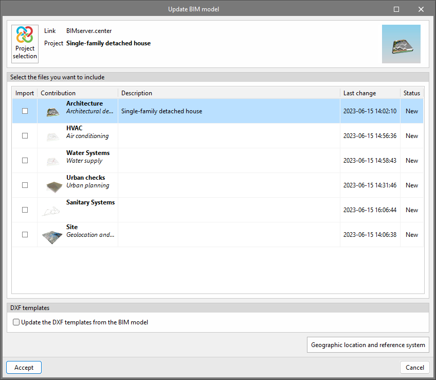
The "Update" option can be used to update the information in the models previously imported into the project or import new models if desired.
In the "Update BIM model" window, via the "Project selection" option, users can choose which project is connected to the BIM model in Open BIM Site from the user's project list in BIMserver.center.
Using the "Geographic location and reference system" option, users can set the geographic location data and the reference system of the model.
In the update, the program allows users to "Update the DXF templates from the BIM model".
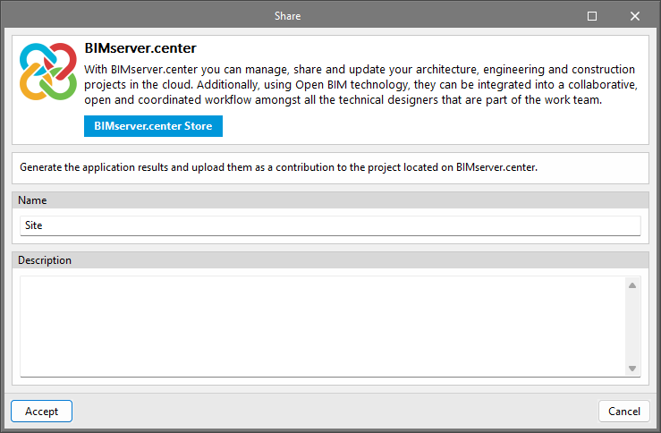
Sharing the BIM model with other users
Using the "Share" option, the information contained in the model developed in Open BIM Site can be exported to the BIMserver.center platform.
During the export process, users can define different details related to the identification of the files to be exported and the types of files to be generated.
Direct connection to other programs
Like other CYPE tools connected to the BIMserver.center platform, Open BIM Site offers direct connection options to CYPE Architecture to carry out the next steps in most workflows.
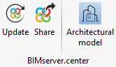
Via the BIMserver.center menu, in addition to updating and sharing files, users will be able to send the Open BIM Site BIM model to:
- CYPE Architecture, for the architectural modelling of buildings.


