Entering infrastructure elements into the diagram
The "Diagrams: Analysis" tab can manually generate telecommunications infrastructure diagrams based on the information from the model developed in the "3D Model" tab, using the available drawing tools:
- To compose the diagrams from scratch, first create the sheets of the necessary formats using the options on the left side. Then, insert the diagram elements into the work area on the right side using the options in the top toolbar.
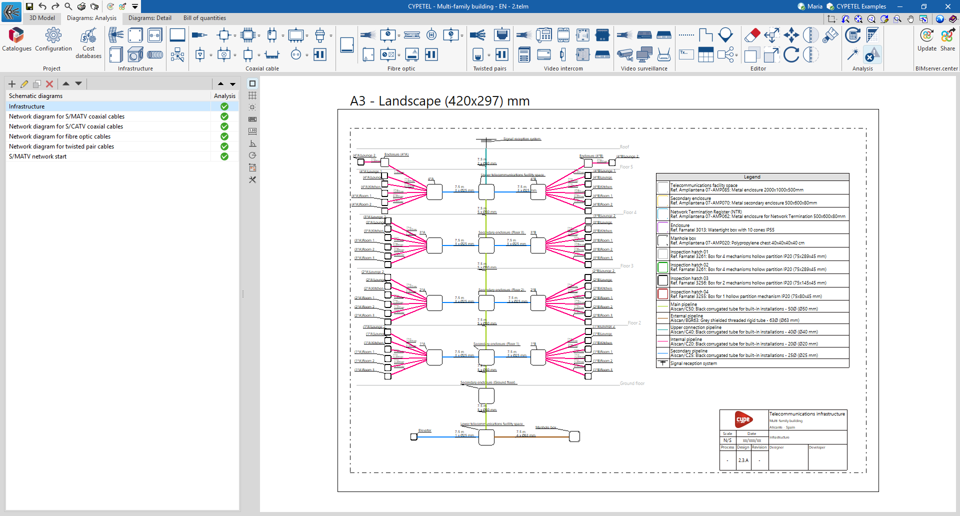
Within the "Diagrams: Analysis" tab, in the "Infrastructure" group of the main toolbar, you will find the options that allow you to insert the elements of the telecommunications infrastructure:

- Signal reception system*
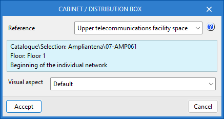
- Cabinet / Distribution box*
- Junction box*
- Manhole box*
- Outlet box*
- Conduit
*The data for these infrastructure elements can be linked to the 3D model using the selection list and disappear once they have been entered.
In the case of conduits, the link to the elements of the 3D model is made automatically, as it analyses the connections between elements in the diagram.