
Tools in the "Drawings" tab
The "Drawings" tab within the "Code compliance" interface creates and edits the drawings for the building's thermal envelope.
Floor plans are generated automatically from the BIM model. You can also import and view templates in DXF/DWG format from the BIM model using the "DXF-DWG Templates" button on the top toolbar.
This tab features an interface comprising the following sections:
Views
In this area, which is located by default at the top of the left-hand side, you can select the view to be displayed in the workspace (floor plans, 3D views, elevations, etc.). Views can be created and edited in the section of the same name on the "Building" tab.
Project
This area, located at the bottom of the left-hand side, features a navigation tree where you can select the zones, spaces, structural elements and openings that make up the building. In the workspace, the program highlights in orange the model elements associated with the level selected in the tree.
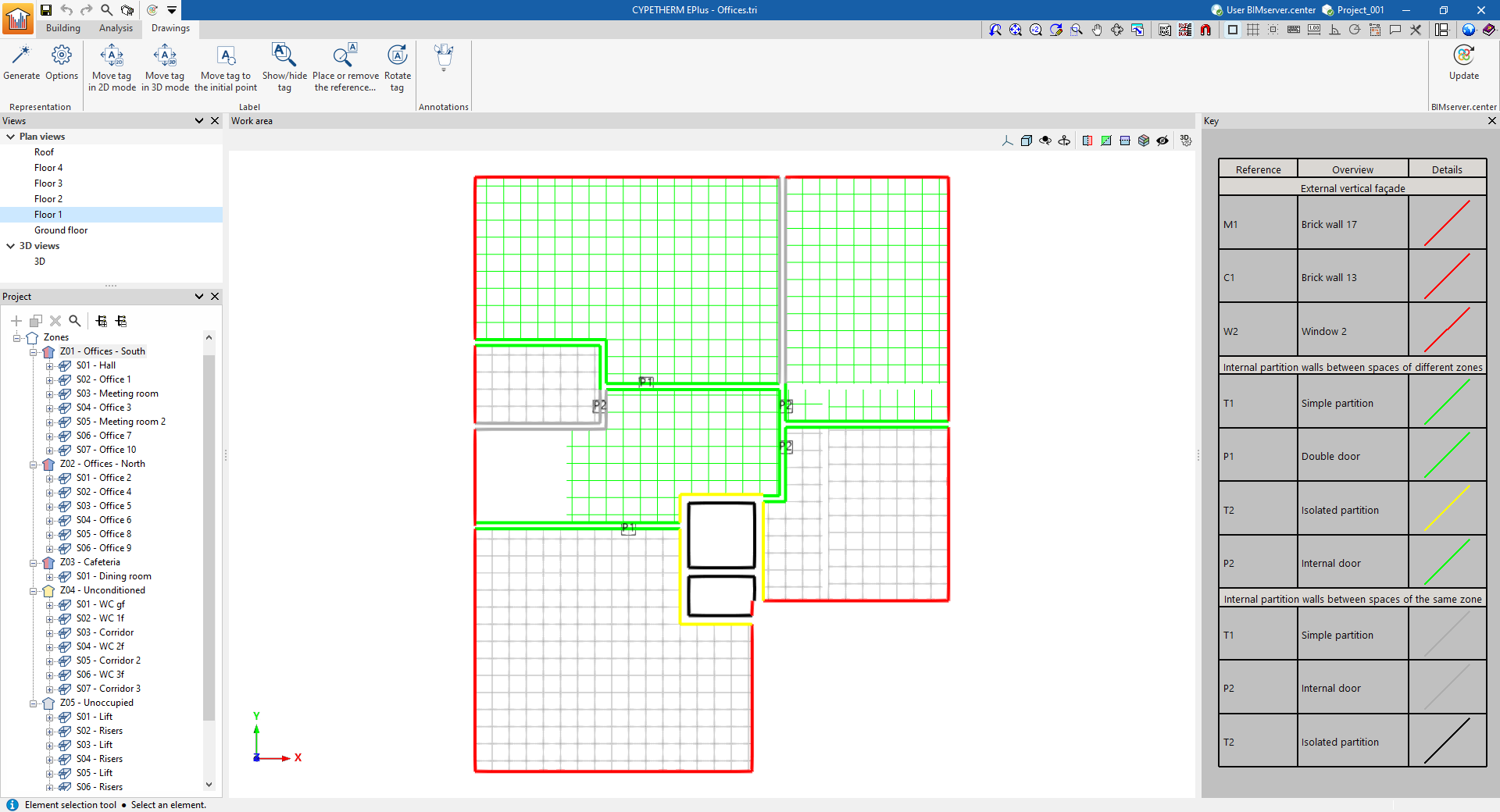
Work area
The work area, located at the centre of the interface, is a three-dimensional environment where the model is displayed according to the selected view. The elements of the envelope are coloured according to the key provided.
Key
In this area, on the right-hand side, the map key is displayed, showing the "Details" of the graphic representation used for each feature, its "Reference" and its "Description".
The top toolbar contains the following features:
"Representation" section

- Generate
Generates the construction drawings.
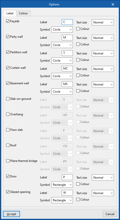
- Options
Manages the label and colour of model elements in the drawings.- "Label" tab
Edits the label text, its symbol, the text size and colour for each element of the model:- Façade
- Party wall
- Partition wall
- Curtain wall
- Basement wall
- Slab-on-ground
- Overhang
- Floor slab
- Roof
- Plane thermal bridge
- Door
- Glazed opening
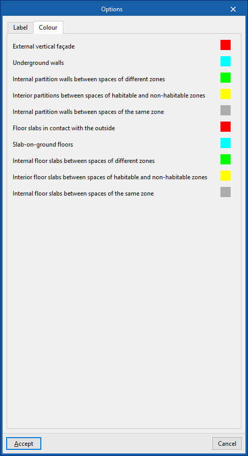
- "Colour" tab
Changes the display colour of model elements according to their category:- External vertical cladding
- Underground walls
- Internal partition walls between spaces of different zones
- Internal partitions between spaces of habitable and non-habitable zones
- Internal partitions between spaces of the same zone
- Floors slabs in contact with the outside
- Slab-on-ground floors
- Internal floor slabs between spaces of different zones
- Internal floor slabs between spaces of habitable and non-habitable zones
- Internal floor slabs between spaces of the same zone
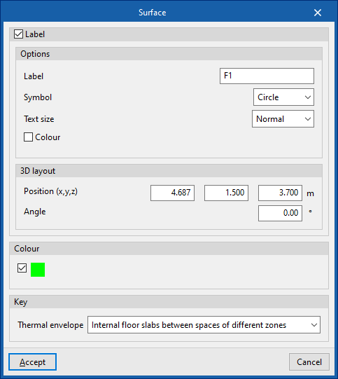
- "Label" tab
If necessary, once the drawings have been generated, clicking on each element in the work area opens an editing window where you can modify its properties and those of its label.
"Label" group

The options in this section allow you to perform the following editing operations on the labels generated for the model elements:
| Move label in 2D mode | Moves the selected label on the element's floor plan. | |
| Move label in 3D mode | Move the selected tag in three-dimensional space. | |
| Move the label to the inital point | Resets the label of the selected item to its default value. | |
| Show/hide label | Shows or hides the label of the selected item. | |
| Place or remove the label reference line | Shows or hides the line linking the label to the selected element to which it refers. | |
| Rotate label | Rotates the label. |
"Notes" group

The options in this group allow you to insert the following drawing elements:
| Elevation | Enters a dimension between two selected points, specifying the colour and line weight, as well as the text size. | |
| Line | Inserts a line between two selected points, specifying its colour and thickness. | |
| Text | Enters some text and a reference line, specifying the colour, line thickness and text size. | |
| Text box | Inserts a text box that is left-aligned, right-aligned or centred, specifying the text colour and size, the border properties and the background fill. | |
| Bow | Enters an arc and, if you wish, its radius, specifying the line colour and thickness and the text size. | |
| Circle | Enters a circle and, if you wish, its radius or diameter, specifying the line colour and thickness and the text size. | |
| Rectangle | Draws a rectangle and, if you wish, its area, specifying the line colour and thickness and the text size. | |
| Area | Enters a polygon using points and, if you wish, its area, specifying the line colour and thickness and the text size. | |
| Polyline | Draws a polyline using points, specifying its colour and line weight. | |
| Edition | Edits the properties of the selected drawing object. | |
| Delete | Deletes the selected drawing resources. | |
| Move | Moves the selected drawing object or parts of it. | |
| Assign | Assigns the properties of one drawing resource to others. When you select a drawing resource, any resources with the same properties are highlighted in orange. |
| Note: |
|---|
| Drawings created and edited in the "Drawings" tab can be printed later using the "Drawings" option at the top of the interface or via the "Drawings" option in the "File" menu. |