
Edge processing
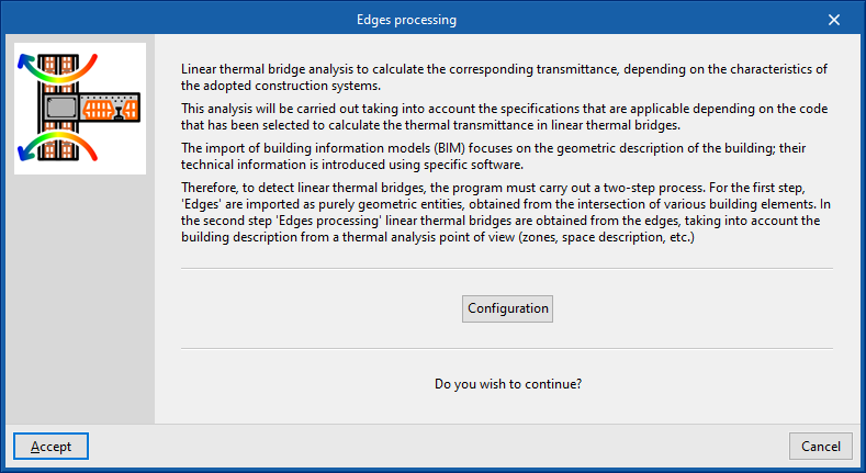
The analysis of linear thermal bridges enables the corresponding linear thermal transmittances to be calculated based on the characteristics of the construction systems adopted. This analysis is carried out taking into account the applicable specifications in accordance with the standard selected for calculating the thermal transmittance of linear thermal bridges.
The import of Building Information Modelling (BIM) data focuses on the geometric description of the building. Technical information is entered into specific software programs. Therefore, when detecting linear thermal bridges, the program carries out a two-stage process:
| Note: |
|---|
| The IFC4 standard does not cover the concept of linear thermal bridges. For this reason, CYPE has created an entity so that when an IFC4 file generated by technologies such as IFC Builder or Open BIM Analytical Model is imported, the intersections of the structural elements (edges) can be displayed for subsequent processing in CYPETHERM EPlus. |
- In the first stage, the building’s edges are imported as purely geometric entities, derived from the intersection of various structural elements. This is done by generating the building model during the import process of a BIM model containing this information, which is held in the BIMserver.center project. At this stage, the thermal bridge library contains all the building’s edges as geometric entities derived from the intersection of the various structural elements. Some of these edges may give rise to linear thermal bridges, so a second step is required.
- In the second stage, using edge processing, linear thermal bridges are identified based on the edges and in accordance with the building’s thermal analysis specifications (zoning, description of spaces, etc.). The program analyses the building and detects the geometric edges located between a habitable space and the exterior, and between a habitable space and a non-habitable space. Not all edges can give rise to linear thermal bridges.
This process can be carried out at the start of a project or when importing a project, or by clicking on the "Edge processing" option in the "Thermal bridges" section of the top toolbar on the "Building" tab. To use this tool, the building must be defined without errors:

When you accept the "Edge processing" window, the program modifies the data relating to "Linear thermal bridges" in the side panel of the "Building" tab, both in the library and in the linear thermal bridges assigned to each room in the tree view that appears when you select the "Zones" level. This generates the necessary types and adjusts the linear thermal transmittance value and category associated with each of the linear thermal bridges.
Edge processing settings
The program analyses the building by identifying the geometric boundaries between a habitable space and the exterior, and between a habitable space and a non-habitable space. Using the configuration options, the characteristics of the main building envelope components are selected so that the corresponding thermal transmittances can be calculated.
To do this, in the "Edge processing" window that appears when you select the option of the same name, click the "Settings" button. This button allows you to adjust the following edge processing parameters:
- Standard
- Numerical analysis of linear thermal bridges (EN ISO 10211) (optional)
- Manual definition of the linear thermal transmittance coefficient
The effects of configuring these sets of parameters are detailed below.
Selecting the codes
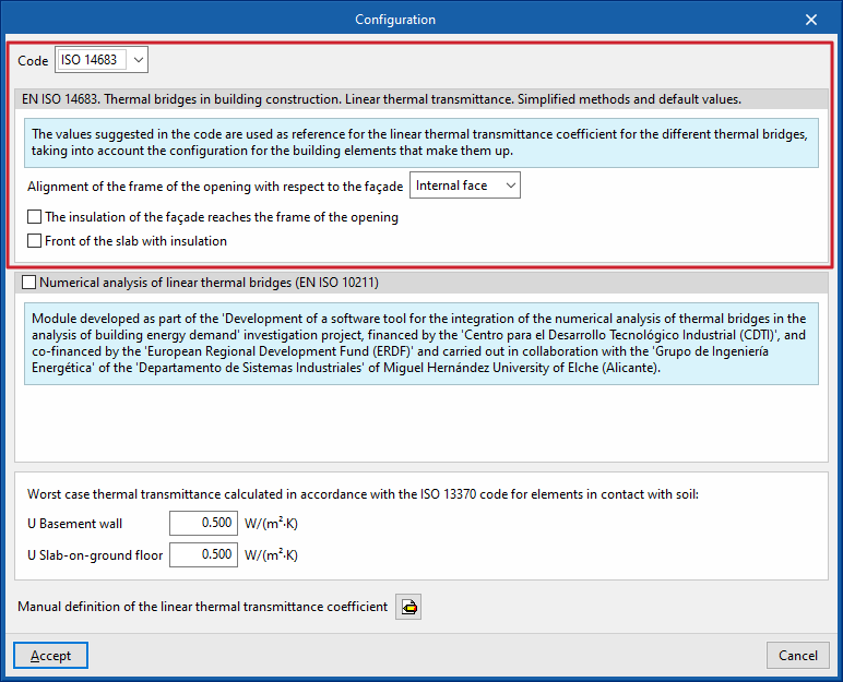
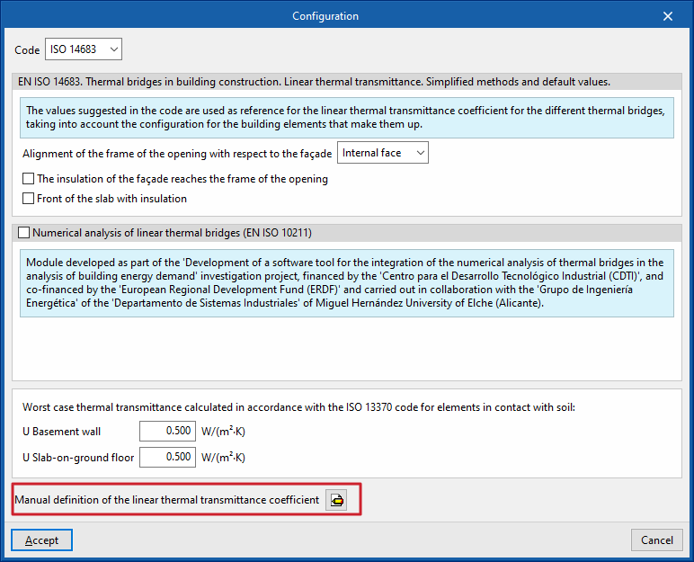
The "Code" drop-down menu allows you to select the reference standard for edge processing. The available codes include the following:
ISO 14683
Please use the following standard as a reference: EN ISO 14683. Thermal bridges in buildings. Linear thermal transmittance. Simplified methods and default values.
The values proposed in this standard for the linear thermal transmittance of the various thermal bridges are used as a reference, taking into account the configuration of the structural elements that make them up.
The options available under this standard are as follows:
- Alignment of the opening frame with the building envelope (against the inner face / centred / against the outer face)
- The insulation of the building envelope extends to the frame of the opening (optional)
- Insulated floor slab (optional)
Numerical analysis of linear thermal bridges (EN ISO 10211)
Enabling this section allows the thermal transmittance of linear thermal bridges to be determined by solving and post-processing a finite element heat transfer analysis model, based on the EN ISO 10211 standard.
This module has been developed as part of the research project "Development of a software tool for integrating the numerical analysis of thermal bridges into the calculation of energy demand in buildings", funded by the Centre for Industrial Technological Development (CDTI) and co-funded by the European Regional Development Fund (ERDF), and carried out in collaboration with the Energy Engineering Group of the Department of Industrial Systems at the Miguel Hernández University of Elche (Alicante).
| Note: |
|---|
| This functionality is identical to that offered by the standalone program CYPETHERM BRIDGES. |
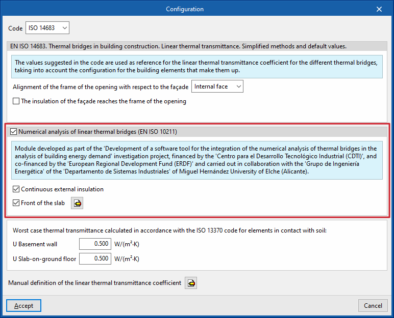
The options available in this section are as follows:
- Continuous external insulation (optional)
- Slab face (optional)
Defines the material layers of the slab face by entering their technical characteristics, such as thickness, thermal conductivity, thermal resistance, density and specific heat.
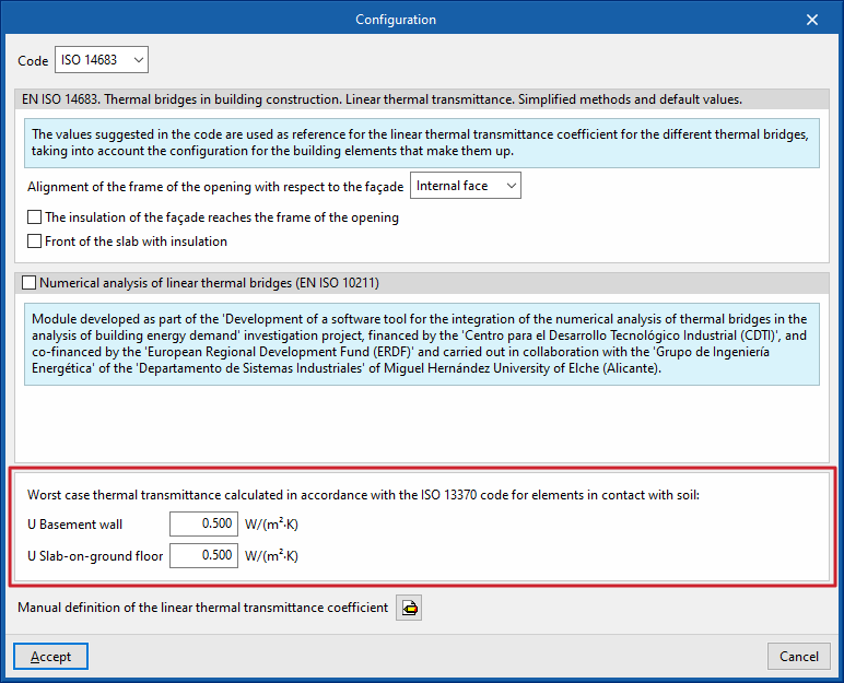
Worst case thermal transmittance calculated in accordance with ISO 13370 for elements in contact with soil
This section defines the thermal transmittance values for basement walls and floors in contact with the ground:
- Basement wall
- Slab-on-ground floor
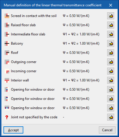
Manual definition of the linear thermal transmittance coefficient
Clicking on the edit button in this section opens the "Manual definition of linear thermal transmittance" window, which displays the types of thermal bridges associated with the selected code.
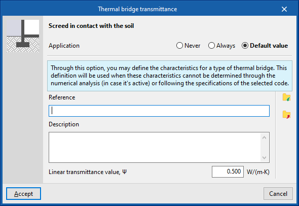
For each type of thermal bridge, by clicking on the edit button on the right, you can choose from the following three options, which allow you to adjust the definition of its linear thermal transmittance:
- Never
The thermal properties of the selected linear thermal bridge are never
taken into account. - Always
Take into account the thermal properties defined for the selected linear thermal bridge. The program allows you to enter a "Reference", a "Description" and the "Linear transmittance value, ψ" for the type of thermal bridge. - Default value
The thermal properties defined for the selected linear thermal bridge will be used in the calculation when it has not been possible to determine them either through numerical analysis (if enabled) or in accordance with the specifications of the reference standard used. Similarly, the program allows you to enter a "Reference", a "Description" and the "Linear transmittance value, ψ" for the bridge type, which will only be used in the case described.
In addition, when you select the "Always" or "Default" options, the program displays data import wizards on the right-hand side, allowing you to import data from various regulatory catalogues or files on your hard drive.
Order of priority for assigning thermal parameter values
Consequently, the program follows this order of priority when assigning thermal parameter values during edge processing:
- Value entered manually using the "Always" or "Never" option
These values can be defined for each type of thermal bridge in the "Settings" window by editing the "Manual definition of the linear thermal transmittance coefficient" section, selecting a specific type of thermal bridge, and finally choosing the "Always" or "Never" option. - Value calculated by numerical analysis of linear thermal bridges
This module is enabled in the "Settings" window and applies to the types of thermal bridges being analysed. - Value derived from the reference standard
The reference standard is selected in the "Standard" section of the "Settings" window. - Value entered manually using the “Default value” option
These values can be defined for each type of thermal bridge in the “Settings” window by editing the “Manual definition of the linear thermal transmittance coefficient” section, editing a specific type of thermal bridge, and finally selecting the “Default value” option.