Managing own shadows and remote shadows
Shadows due to the building's own elements and shadows due to nearby buildings or obstacles are imported from the BIM model information and appear in the "Own shadows" and "Remote shadows" sections of the tree diagram on the left side of the "Building" tab.
In these sections of the diagram, shadows can be viewed, added, deleted and edited. These elements are defined as planes at specific positions in space that will cast shadows on the building during the energy simulation.
In the list of elements that appears in the main area when selecting these sections of the tree, the shades with the unchecked box in the "Checked" column will not intervene in the energy simulation.
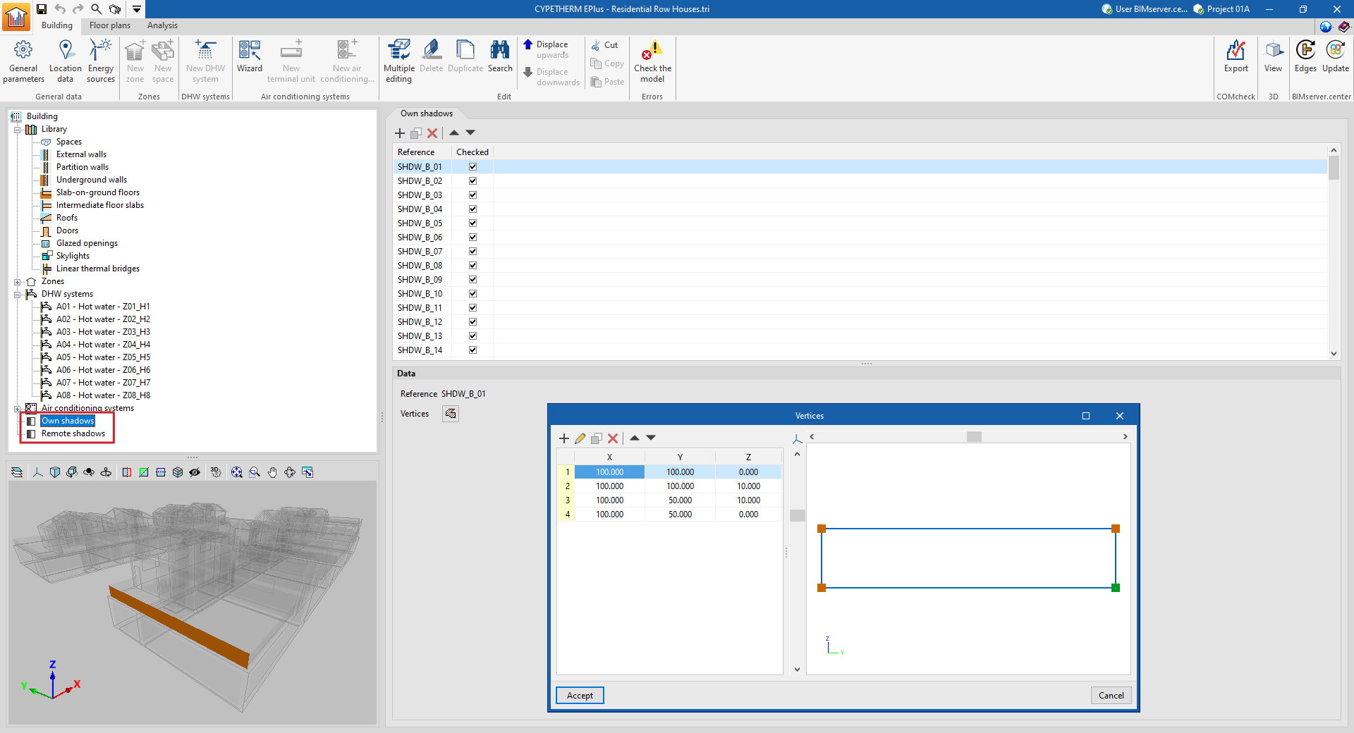
Each shadow, own or remote, is defined only by its reference and the vertices of a polygon:
- Reference
The numbered reference of the shadow is automatic and depends on its position in the table. - Vertices
Displays and defines the global coordinate points "x", "y" and "z" that determine the position and surface of the shadow.