Editing thermal zones in the building tree diagram
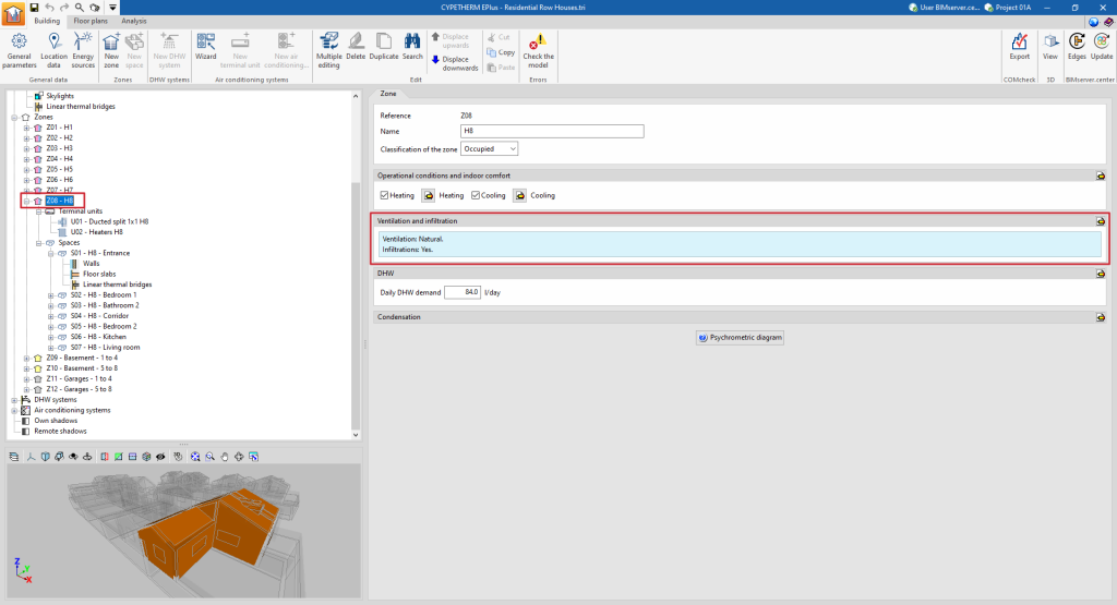
When a thermal zone is selected in the tree diagram in the left-hand side panel of the "Building" tab, the 3D model viewer lights up and the "Zone" panel is displayed in the main area, where the following properties of the zone are defined:
- Reference
The numbered reference of the zone is automatic and depends on its position in the diagram.
- Name
Name of the zone. This parameter can be edited directly.
- Classification of the zone ( Habitable / Non-habitable / Not defined)
All spaces included in the zone must be the same type (habitable or non-habitable) as the one chosen in this drop-down list. In the tree diagram, a zone classified as non-habitable or not defined will be shown with a grey symbol. A zone classified as habitable will have a coloured symbol depending on its operational conditions: yellow if no setpoint temperature has been defined (unconditioned habitable zone), red if a heating setpoint temperature is defined and blue if a cooling setpoint temperature is defined.

"Operational conditions and indoor comfort" section
Defines the operational conditions and comfort temperatures of the thermal zone. All spaces included in the zone share these conditions.
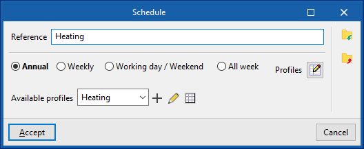
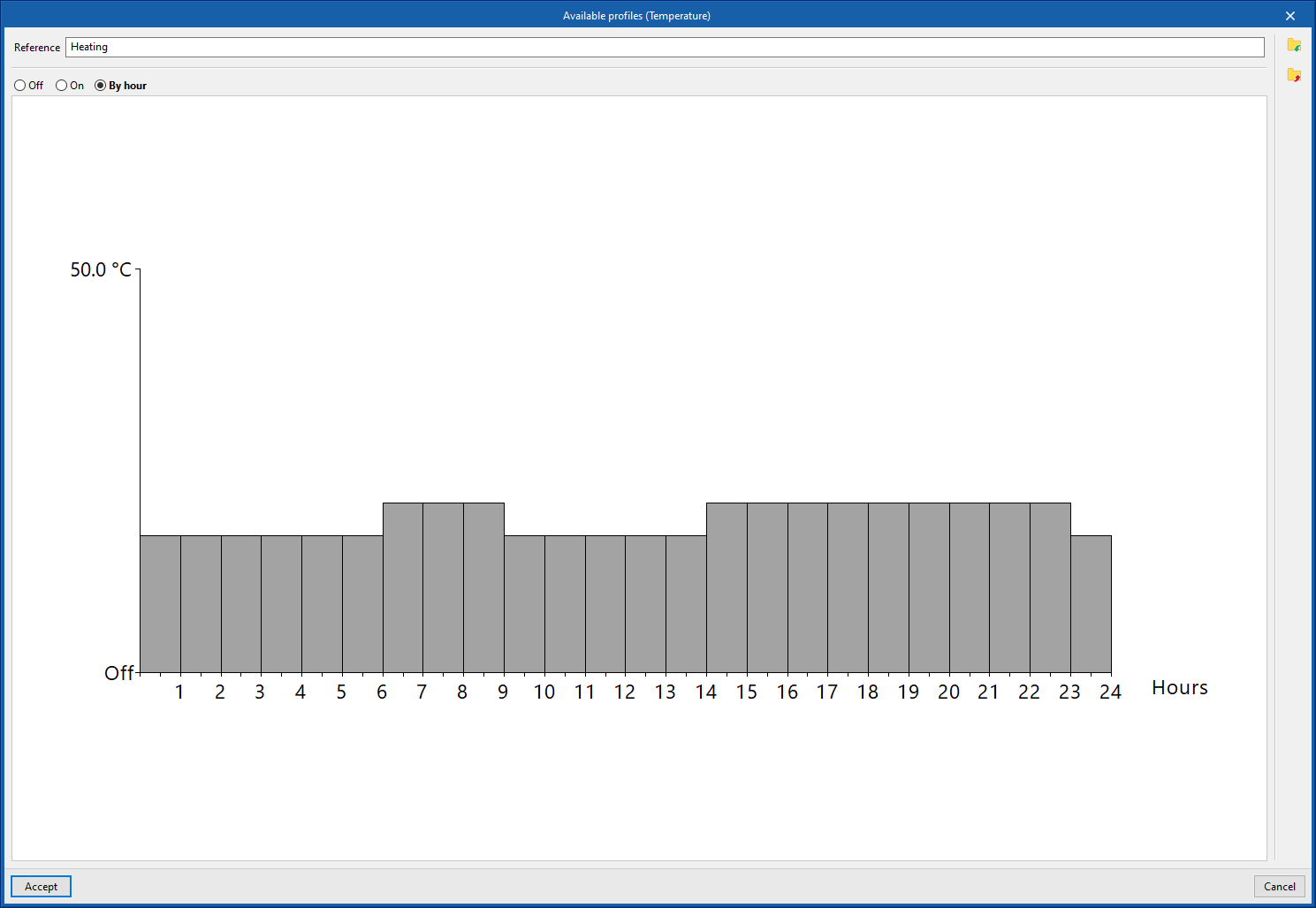
- Heating (optional)
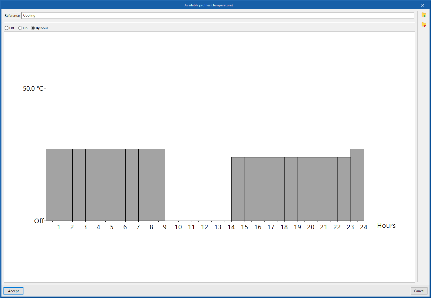
Defines the heating setpoint temperature of the zone by means of an hourly profile. - Cooling (optional)
Defines the cooling setpoint temperature of the zone by means of an hourly profile.


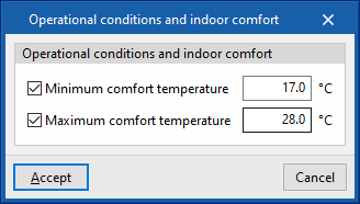
- Editing advanced properties
Using the edit option on the right-hand side of the section, a maximum and minimum indoor comfort temperature can be defined. These temperature values are used in the "Indoor comfort" report to make comparisons with the indoor temperature of the zone. These comfort temperatures are not used in the EnergyPlus™ simulation.- Minimum comfort temperature (optional)
- Maximum comfort temperature (optional)
"Ventilation and infiltration" section
This section defines the ventilation and air infiltration of the zone.
- Editing advanced properties
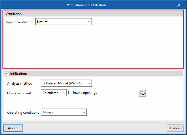
The following parameters can be defined using the edit button on the right-hand side of the section:- Ventilation
The type of ventilation must be defined for all spaces in the zone, between:- Natural
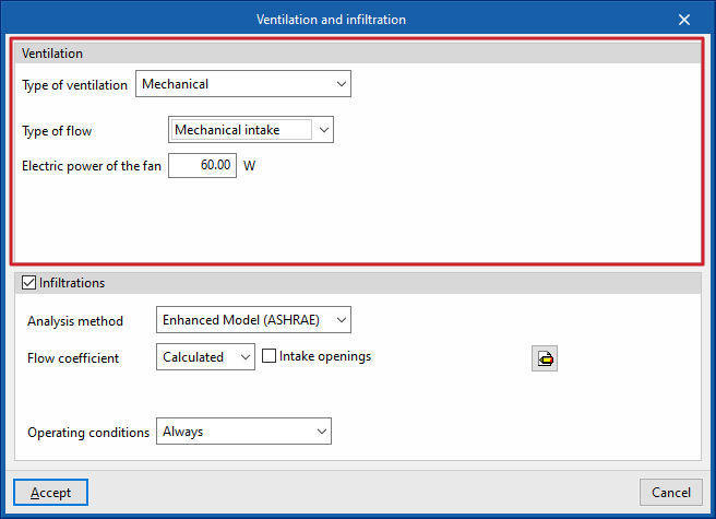
The ventilation flow defined in the zone spaces enters directly. - Mechanical
The characteristics of the fan(s) (dual flow option) driving the defined ventilation flow in the spaces of the zone are defined:- Type of flow (Mechanical intake / Mechanical extraction / Double flow)
- Electric power of the fan
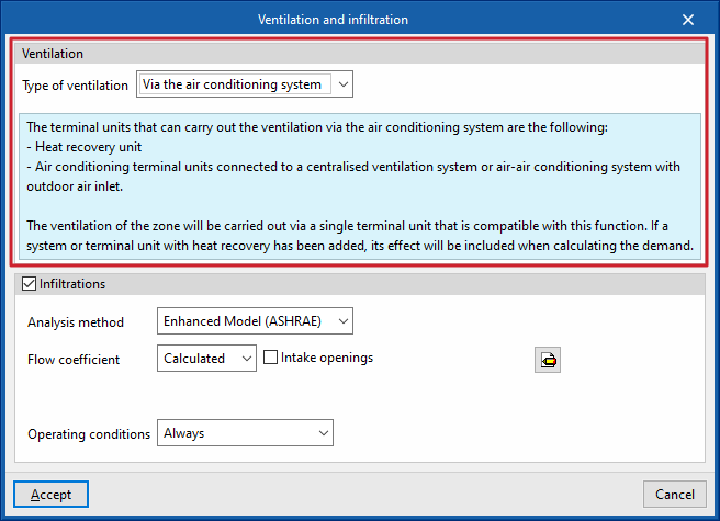
- Via the air conditioning system
The defined ventilation flow in the spaces of the zone shall be provided by the defined air-conditioning system associated with the zone, which shall be compatible with this function.
- Natural
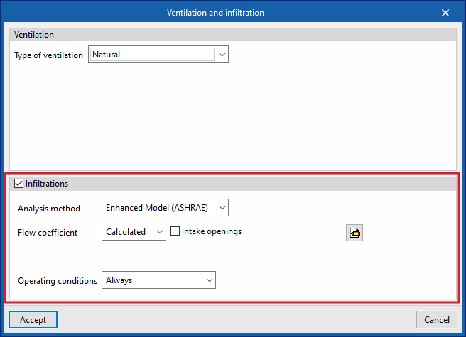
- Infiltrations (optional)
The existence of infiltrations in each zone can be defined, i.e. a flow of air from the outside that enters the group of rooms in an undesired way. Different possibilities of defining this flow rate are offered, through two design methods and different schedules.- Analysis method: Enhanced Model (ASHRAE)
This calculates the infiltrations using the indicated design model. The following parameters must be defined:- Flow coefficient
This can be defined directly or calculated from the data entered.- Defined
- Calculated
- Intake openings (optional)
- Surface
- Intake openings (optional)
- Analysis data
The program offers tools for defining this data by clicking on the buttons on the right-hand side of the screen.- Stack coefficient
- Pressure exponent
- Wind coefficient
- Shelter factor
- Flow coefficient
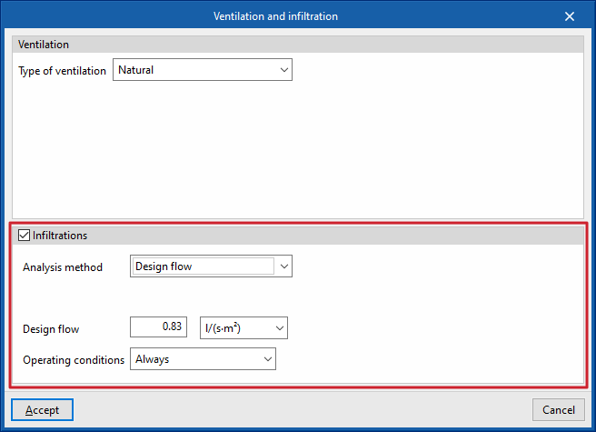
- Analysis method: Design flow
Used to directly enter the flow rate due to infiltration. - Operating conditions (Only with nil ventilation / Schedule / Always)
Establishes the conditions under which infiltration occurs in the zone.
- Analysis method: Enhanced Model (ASHRAE)
- Ventilation
Ventilation editing:
Infiltration editing:
"DHW" section
This section will appear in each heating zone if in "General parameters" the "Demand per heating zone" option has been selected under "Daily DHW demand".
Thus, the following parameters are defined in relation to the domestic hot water demand in each zone of the building. If the "Total building demand" option has been chosen, these definitions have to be made for the total building in the "General parameters".
- Daily DHW demand
Volume of domestic hot water (DHW) consumed in a day in the zone. - Editing advanced properties
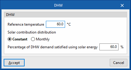
The following parameters can be defined using the edit button on the right hand side of the section:- Reference temperature
Production temperature of the DHW volume defined in "Daily DHW demand". - Solar contribution distribution
The percentage of the energy demand for DHW production covered by the solar thermal system of the building is defined. A constant or monthly value can be defined.- Constant / Monthly
- Percentage of DHW demand met by solar energy
- Reference temperature

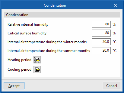
"Condensation" section
This section defines the indoor environment parameters for calculating the check for surface and interstitial condensation if this option has been activated under "General parameters".
- Editing advanced properties
The following parameters can be defined using the edit button on the right hand side of the section:- Relative internal humidity
- Critical surface humidity
- Internal air temperature during the winter months
- Internal air temperature during summer months
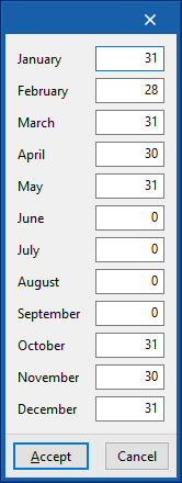
- Heating period (number of days per month)
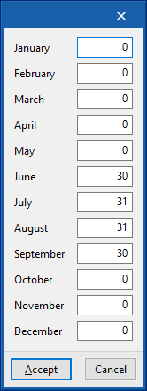
- Cooling period (number of days per month)
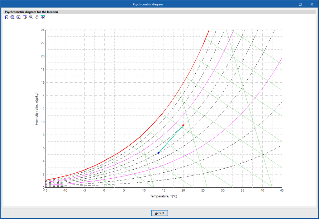
- Psychrometric diagram
Displays the indoor air temperature and humidity points (red colour) defined in this section, and the outdoor air defined in the "Location data" panel.