
Air conditioning systems. Manual definition
Manually defined centralised production systems
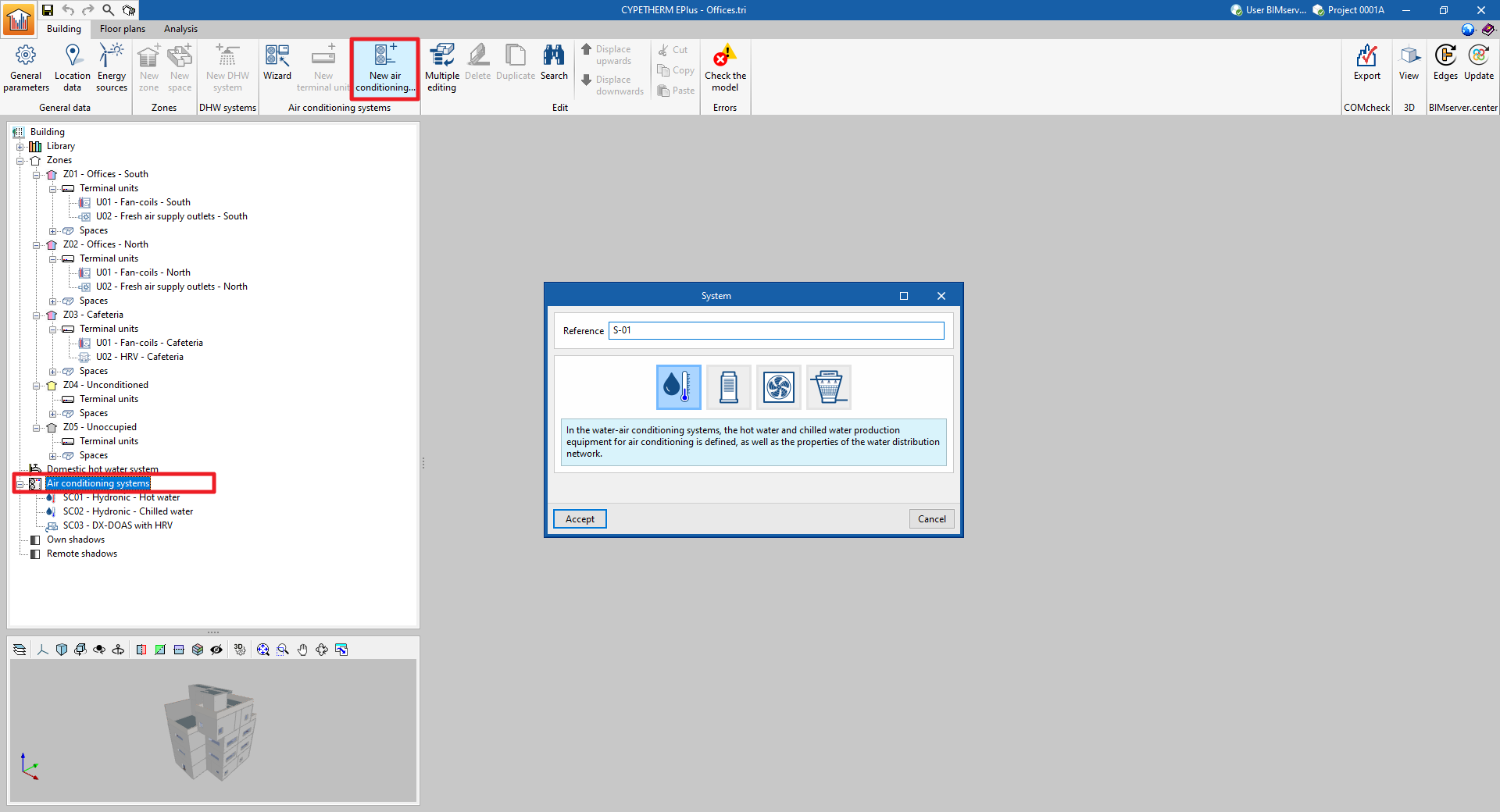
To manually add a new centralised production system, select the "Air conditioning systems" section in the building diagram and click on the "New air conditioning system" button in the top toolbar.
This will display a pop-up window in which the type of production system can be selected from "Water-air conditioning system", "Direct expansion system" (refrigerant), "Air-air conditioning system" or "Water-cooled system".
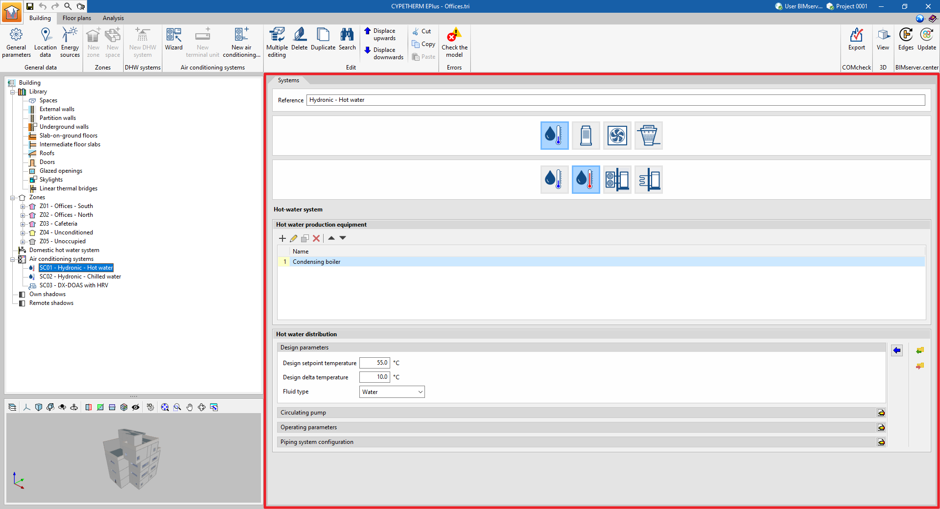
By choosing one of these general typologies, a new window opens where the specific type of system is selected and its characteristics are defined.
The following types and sub-types of centralised production systems are available:
- Water-air conditioning system
- Chilled-water system
- Hot-water system
- Domestic heat pump system
- Geometric heat pump

- Direct expansion systems
- Variable refrigerant flow systems (VRF)
- Multisplit

- Air-air conditioning system
- Central ventilation system
- Heat recovery unit
- Dedicated outdoor air system (DOAS)
- Air handling unit, constant air flow system
- Air handling unit, variable airflow system
- Air handling unit, constant flow all-air system with double duct
- Air handling unit, variable flow all-air system with double duct
- Central ventilation system

- Water-cooled system
- Water-cooled system for reversible heat pumps
- Water-cooled system for chillers
- Water condensation system at a defined temperature

By selecting the type of unit, the editing panel is updated to show its characteristics. In some categories, under the logos of different manufacturers, users are offered the possibility of selecting units from their commercial catalogues. The characteristics of these units are completely defined within the program, so users simply have to indicate the characteristics relating to their installation.
The following general features are offered in the air conditioning editing panels:
 Restores the default values proposed by the program.
- Displays and edits advanced features of the air conditioning system.
 Imports air conditioning system information from a file on disk.
 Exports the climate control system information to a file saved on disk.
If a value is not specified for certain characteristics of the units, such as the nominal capacity of a production unit or the flow rate of a fan, the autosize function of EnergyPlus™ is used. This function will calculate non-user-defined values based on the requirements of the connected terminal units and the unit design characteristics.
When a new centralised production system has been created, it will appear as an element in the "Air conditioning systems" section of the diagram. When it is selected, the editing panel is displayed on the centre right-hand side of the general interface.
Using the options in the "Edit" group of the upper toolbar or by right-clicking on the element in the diagram, it can also be duplicated, deleted, moved in the list, cut or copied.
Manually defining terminal units
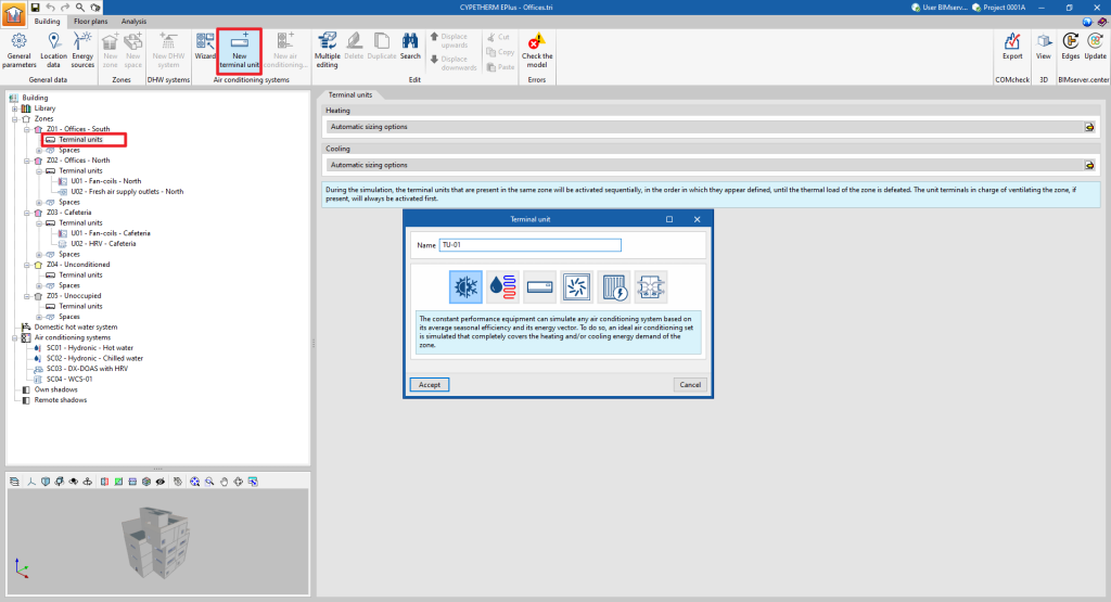
Terminal units for air-conditioning systems are defined manually in a similar way to those for centralised production systems. To add a new terminal unit, select the "Terminal units" section of the building diagram, within the "Zone" where it is to be added, and click on the "New terminal unit" option in the top toolbar.
A pop-up window appears where the type of terminal unit is selected from among "Constant performance equipment", "Water terminal unit", "Direct expansion terminal unit", "Air terminal unit", "Electric heater" and "Heat recovery unit".
By choosing one of these general types, a new window opens in which the specific type of terminal unit is selected and its characteristics are defined.
The types and sub-types of terminal units available are as follows:
- Constant performance equipment
- Heating
- Cooling
- Both

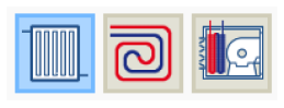
- Water terminal unit
- Radiator
- Radiant floor
- Fan coil
- Direct expansion terminal unit
- Split 1x1
- Multisplit
- VRF
- Packaged terminal unit
- Water to air heat pump
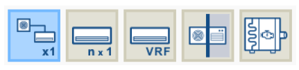
- Air terminal unit
- Air supply outlet
- Air supply outlet, double duct
- Variable air volume box
- Variable air volume box, double duct

- Electric heater

- Heat recovery unit

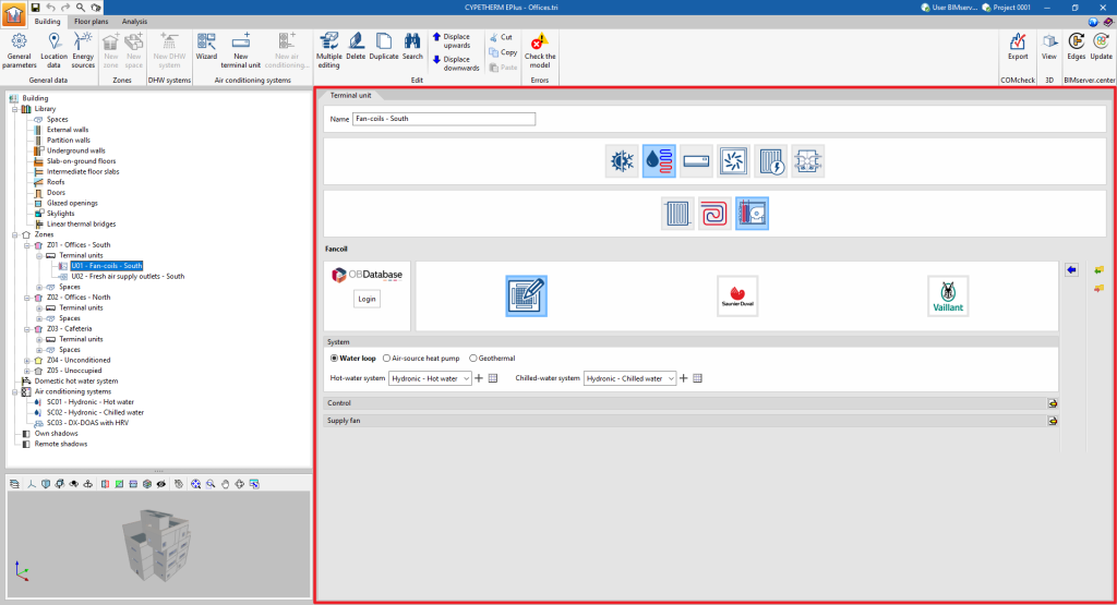
Just as with the centralised part of the air-conditioning systems, selecting the type of terminal unit updates the editing panel to show its characteristics. Within some categories, under the logos of different manufacturers, users can select units from their commercial catalogues. The characteristics of these units are completely defined within the program so that the user only has to indicate the characteristics relating to their installation.
The following general features are provided in the terminal unit editing panels:
- Restores the default values proposed by the program.
- Displays and edits advanced features of the terminal unit.
- Imports terminal unit information from a file on disk.
- Exports terminal unit information from a file on disk.
If a value is not specified for certain characteristics of the equipment, such as its rated power or the flow rate of a fan, the EnergyPlus™ autosize function is used. This function calculates the non-user-defined values based on the thermal loads and autosize options for the zone.
The "System" section appears on the panels of the non-autonomous terminal units. The centralised system to which the unit is connected must be selected. The drop-down menu will only offer the systems compatible with the terminal unit defined in the job.
The list management buttons to the right of the drop-down menu are as follows:
 This defines a new centralised production system, of any type.
 Edits and selects a centralised production system defined in the job.
 Indicates that the selection made in the drop-down is empty or incorrect.
When the creation of a new terminal unit is completed, it will appear as an element within the "Terminal units" section of the diagram within each zone. When selected, its editing panel is displayed in the central right part of the general interface.
Using the options in the "Edit" group of the top toolbar or by right-clicking on the element in the diagram, it can also be duplicated, deleted, moved in the list, cut or copied.
Defining fans and circulator pumps
Within centralised air-conditioning systems, the relevant characteristics of the working fluid distribution network are also defined, which includes the fluid transport equipment, i.e. fans and circulator pumps.
Air-supply terminal units, such as fan coils, direct expansion (refrigerant) indoor units and heat recovery units, also contain fans.
The electricity consumption of these auxiliary units is included in the consumption of the heating and cooling services, except for the consumption of fans for centralised ventilation systems, which are charged to the ventilation service.
Fans
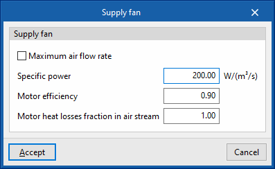
The fans are defined in a similar way for all devices in the program:
- Maximum air flow rate / Air flow (optional)
The air flow passing through the fan. If "Maximum air flow rate" is indicated in the panel, the air flow rate may vary during the simulation up to the value set in this box. If the air flow rate is not specified, the program will calculate the required air flow rate. - Specific power
The fan power consumption per m³/s of air flow it moves. If the performance value of the air conditioning unit includes the fan consumption, the value of the specific power can be set as 0 to avoid accounting for this consumption twice. - Motor efficiency
This is considered in the calculation of the heat losses of the electric motor of the fan, which will affect the supply air temperature according to the definition made in the following variable. - Motor heat losses fraction in air stream
If the supply air flows through the fan motor, the heat losses of the fan motor will cause an increase in air temperature. To consider this, a value of 1 should be set. If, on the other hand, the fan motor is outside the air flow, its heat losses will not affect it, so a value of 0 should be set.
Circulator pumps
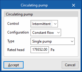
Circulator pumps are also defined in a similar way in the different types of hydraulic circuits:
- Control
- Intermittent
If the control is intermittent, the pump is switched on and off at the same time as the air conditioning system. - Continuous
If the control is continuous, the pump is always on, even if there is no demand. In long periods of no demand, heat losses from the pump accumulate in the fluid, which can cause a significant rise in its temperature.
- Intermittent
- Configuration
The "Constant flow" and "Variable flow" represent a fixed or variable speed pump, respectively. - Type
Allows users to choose the number of identical pumps contained in the hydraulic circuit and their position. - Rated head
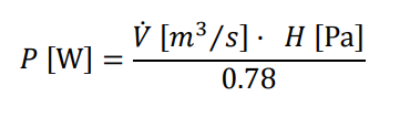
The pump head is involved in the analysis of the power consumption.
The water flow rate in the circuit is automatically determined by the calculation engine based on the heating or cooling demand on the day of design and the "Design temperature difference" specified in the hydraulic circuit.
The electrical power of the circulation pump (P) is obtained from the water flow rate (V̇) and the head (H). The motor considers a fixed pump efficiency value equal to 0.78.
Examples
The combinations of air-conditioning systems and terminal units to be entered into the program for modelling different types of installation are shown below:
| Type of installation | Air conditioning system | Terminal unit |
| Constant performance equipment | None | - Constant performance equipment |
| Electric emitter installation | None | - Electric emitter for heating |
| Boiler, chiller and fan coils (air-cooled condenser) installation | - Water-air conditioning systems. Hot-water system - Water-air conditioning systems. Chilled-water system | - Water terminal unit. Fan coil |
| Boiler and radiator installation | - Water-air conditioning systems. Hot-water system | - Water terminal unit. Radiator |
| Boiler and radiant floor installation | - Water-air conditioning systems. Hot-water system | - Water terminal unit. Radiant floor |
| Aerothermal installation with fan coils | - Water-air conditioning systems. Domestic heat pump system | - Water terminal unit. Fan coils |
| Geothermal installation with fan coils | - Water-air conditioning systems. Geometric heat pump - Water condensation system at a defined temperature | - Water terminal unit. Fan coils |
| VRF/VRV installation (air-cooled condenser) | - Variable refrigerant flow systems (VRF) | - Direct expansion terminal unit. Variable refrigerant flow systems (VRF) |
| 1x1 split installation | None | - Direct expansion terminal unit. Split 1x1 |
| Multisplit installation | - Direct expansion systems. Multisplit | - Direct expansion terminal unit. Multisplit |
| Packaged terminal unit installation (electrical / gas) | None | - Direct expansion terminal unit. Packaged terminal unit |
| Compact equipment installation (hot water) | - Water-air conditioning systems. Hot-water system | - Direct expansion terminal unit. Packaged terminal unit |
| Heat recovery unit installation per zone | None | - Heat recovery unit |
| Centralised ventilation installation with heat recovery unit | - Central ventilation system. Heat recovery unit | - Air terminal unit. Air supply outlet |
| Centralised ventilation system with dedicated outdoor air system (DOAS) | - Central ventilation system. Dedicated outdoor air system (DOAS) | - Air terminal unit. Air supply outlet |
| Constant flow air conditioning installation | - Air handling unit, constant air flow system | - Air terminal unit. Air supply outlet |
| Variable flow air conditioning installation | - Air handling unit, variable flow all-air system | - Air terminal unit. Variable air volume box |
| Constant flow air conditioning installation, double duct | - Air handling unit, constant flow all-air system with double duct | - Air terminal unit. Variable air volume box, double duct |
| Variable flow air-conditioning installation, double ducts | - Air handling unit, variable flow all-air system with double duct | - Air terminal unit. Variable air volume box, double duct |