Inserting building elements
The "Building elements" section of the main toolbar contains the following options:

- Walls and partitions
- Floor slabs
- Openings
- Close elevation change
- Columns
- Thermal breaks
These options allow you to enter the building’s construction and structural elements, depending on what is required for subsequent analysis.
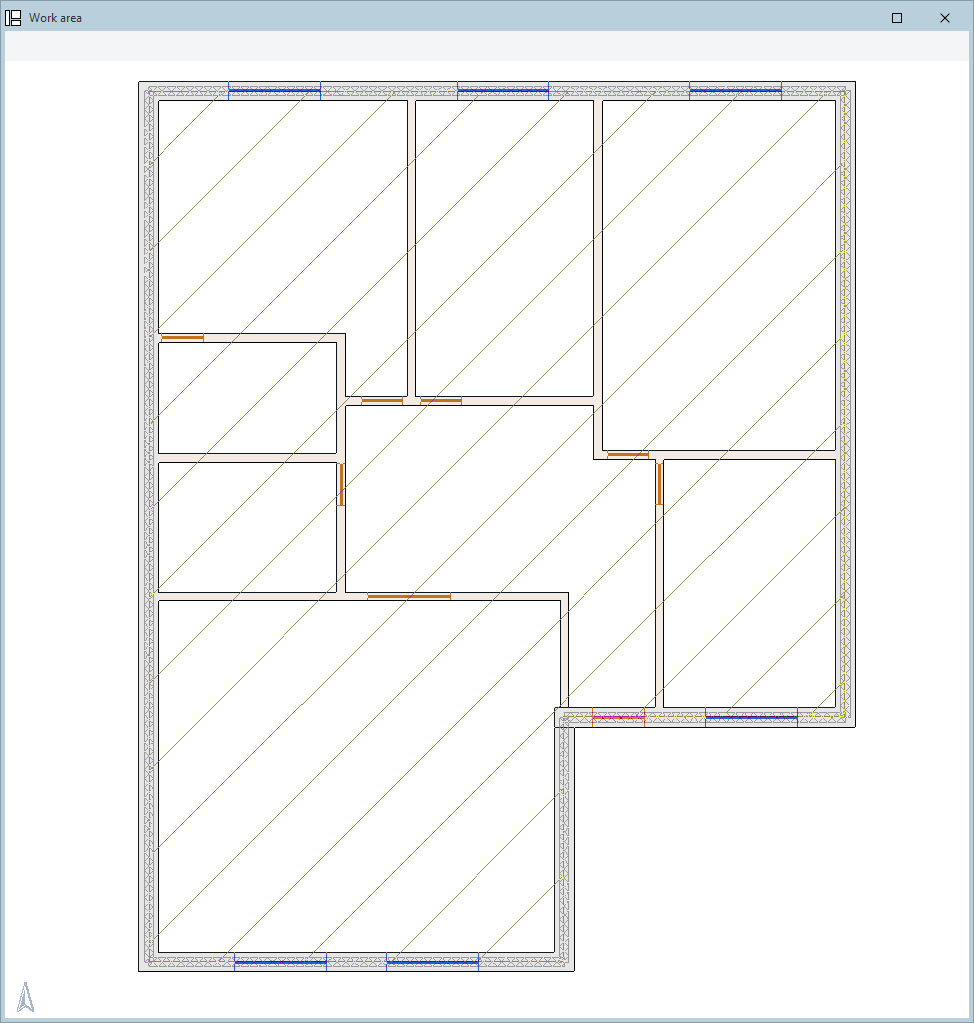
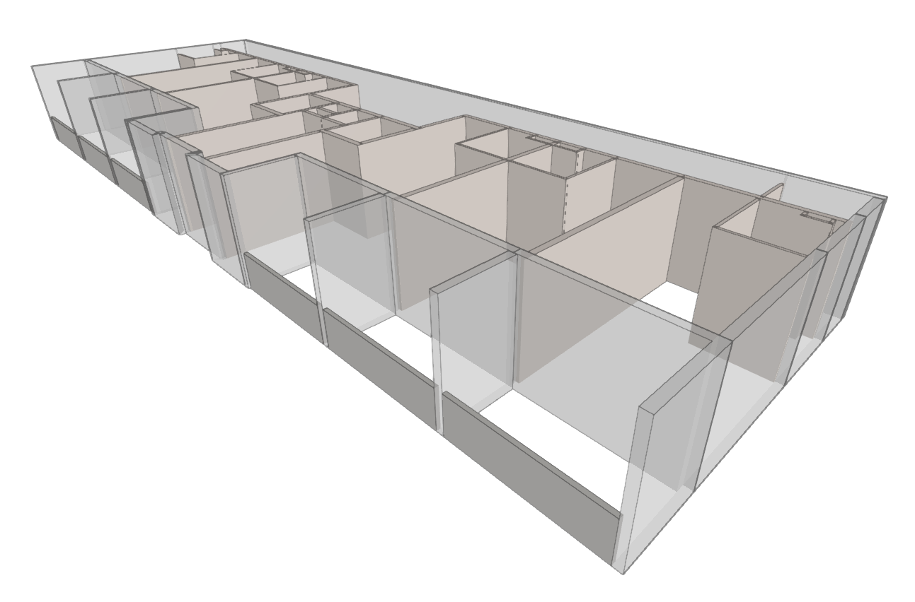
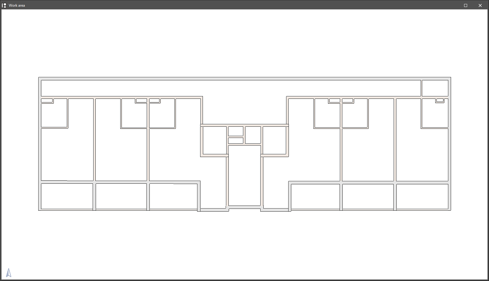
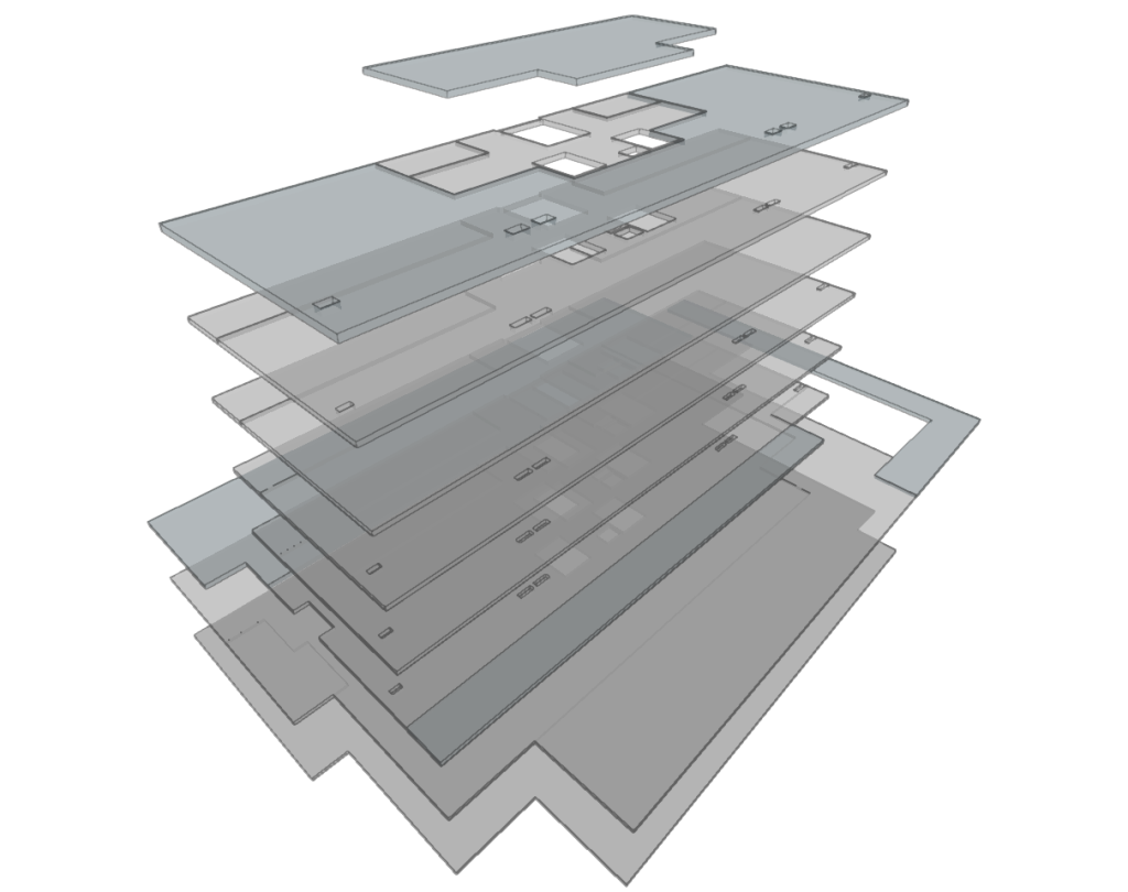
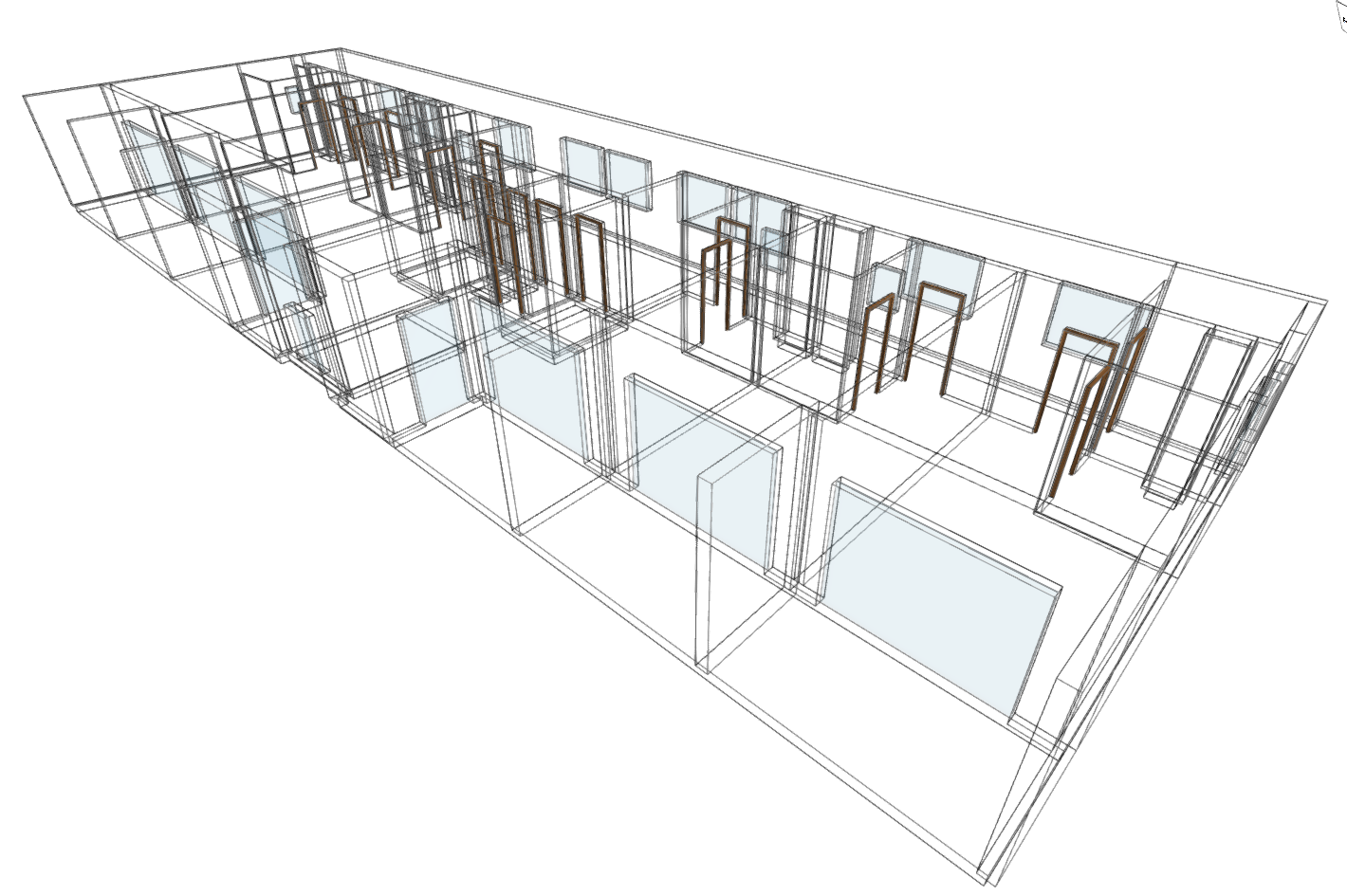
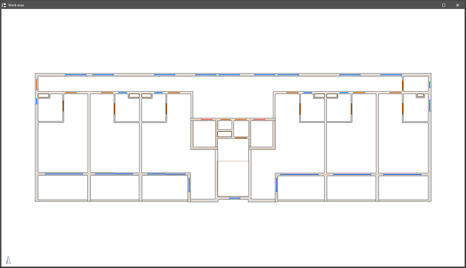
Modelling is carried out floor by floor in a 2D workspace, using 3D elements. A 3D view of the building can be displayed at any time, allowing you to monitor the modelling process.
The building can be modelled in IFC Builder from scratch, with or without the aid of templates or drawings in DXF, DWG, JPEG or BMP format. Using these templates speeds up the manual data entry process.
Creating and managing property types
When you insert an instance of a building element using any of the options mentioned, the program opens a window where you can select the type from a drop-down menu from those previously created using the "Libraries" option in the "Project" panel.
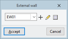
To the right of the drop-down menu, the following options are available for creating and editing library types and for accessing the library of elements in the relevant category directly:
| New | Create a new type. | |
| Edit the selected type | Edit the type selected from the drop-down menu. | |
| Edit the list of elements | This opens the list of types corresponding to the category of the element being entered. From this list, you can also create, edit, delete or reorder types, as well as import and export types to files on the hard drive, in the same way as you would using the "Libraries" option in the "Project" group for the selected element's category. |
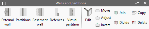
Walls and partitions
The "Walls and partitions" menu allows you to add and edit vertical geometric elements in the model, such as facades, party walls, internal partitions, basement walls, parapets and virtual partitions.
The following types of walls and partitions are available:
- External wall
A vertical partition separating a room within a building from the outside environment or, in the case of a party wall, separating a room within a building from the space belonging to other buildings. - Partitions
wall A vertical partition separating two interior spaces within a building. - Basement wall
A vertical partition between a part of a building and the ground. - Defences
Allows you to model railings, balustrades, perimeter parapets and other guardrails. - Virtual partition
A vertical element with no thickness used to demarcate spaces. It can be placed between two spaces in the model that are not separated by a physical barrier in the actual building (for example, between an open-plan kitchen and the living room).
The tools for editing walls and partitions are as follows:
- Edit
Allows you to edit the wall type to modify its properties or change the type assigned to the selected element. - Move
Allows you to reposition walls and partitions by moving them parallel to their current position or by moving one of their ends. - Adjust
Allows you to adjust the position of the selected wall or partition relative to the reference line, either by aligning it along one of its faces or along its centreline. - Invert
Inverts the direction in which the partitions are inserted. - Join
two walls. - Divide
Splits a wall in two at a point specified by the user. - Copy
Copies the type of one wall to another. - Delete
Removes the selected walls and partitions.
Floor slabs
The "Floor slabs" menu allows you to add and edit horizontal or sloped geometric elements in the model, such as floor slabs, floor-to-floor slabs, and flat and sloped roofs.
The following types of floor slabs are available:
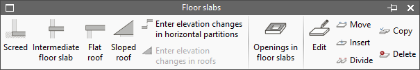
- Screed
Allows you to define floor slabs and sanitary floor slabs. - Intermediate floor slab
This allows you to add an internal floor slab, which separates two areas of the building, or a cantilevered floor slab, which separates an interior space above from the outdoor area below. - Flat roof
Allows for the installation of a flat roof. - Sloped roof
Allows you to add an overhang to a pitched roof.
The program offers two options for adjusting the geometry of horizontal slabs and pitched roofs:
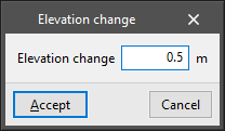
- Applying elevation changes to horizontal partitions
This allows you to apply a positive or negative elevation changes to a ground-floor slab, an intermediate-floor slab, or a roof slab relative to the floor level. This elevation changes shifts the slab parallel to the ground.
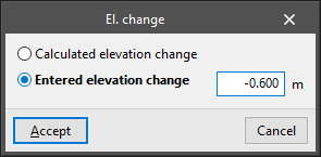
- Apply elevation changes to roofs
This allows you to apply a slope to the vertices of the polygon that defines a roof. The slope can be:- Calculated elevation changes
The program calculates the elevation difference at a given point based on the elevation differences entered for the other points in the chain of points that defines the roof perimeter. - Entered elevation changes
The user enters the elevation changes of the selected point relative to floor level, whether positive or negative.
- Calculated elevation changes
From the "Floors" menu, you can also add openings in floors by drawing their perimeter outline on the floor plan of a previously added floor:
- Openings in floor slabs
The tools for editing floor slabs are as follows:
- Edit
Allows you to edit the floor type to modify its properties or change the type assigned to the selected element. - Move
Allows you to modify the shape of a slab by repositioning the vertices or sides of the polygonal line that defines its perimeter. - Insert
Allows you to insert an additional point on the polyline that defines the perimeter of the slab. - Split
Allows you to split a slab into two slabs by drawing a polygonal line between two points on its perimeter. - Copy
Copies the type of one floor slab to another. - Delete
Deletes the selected floor slabs.
Openings
The "Openings" menu allows you to add and edit openings such as doors, windows, openings and skylights in the model. You must first add the wall or floor slab in which you wish to create the opening.
The following types of openings are available:
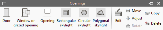
- Door
Adds a door to a wall or partition. - Window or glazed opening
Adds a glazed opening to a wall or partition. The following parameter is defined:- Ground clearance
- Opening
Creates an open opening in a wall or partition. The following parameter is defined:- Ground clearance
- Rectangular skylight
Allows you to insert a rectangular skylight into a floor slab. The following parameters are defined:- Long
- Width
- Circular skylight
Adds a circular skylight to a floor slab. The following parameter is defined:- Diameter
- Polygonal skylight
Adds a user-defined free-form polygonal skylight to a floor slab.
The gap editing tools are as follows:
- Edit
Allows you to edit the opening type to modify its properties or change the type assigned to the selected element. - Move
Moves an existing opening
- For doors, windows or glazed openings, if the width of the opening is fixed, this changes its position to another location on the floor plan whilst keeping its dimensions constant. If the width is not fixed, it allows one end of the opening to be moved along the wall where it is situated, increasing or decreasing its size.
- For circular and rectangular skylights, it allows their position on the floor plan to be moved.
- For polygonal skylights, it is possible to move the vertices and sides of the polygon that defines them. - Adjust:
Move the doors and windows to align them with the interior beams, the exterior beams, or the centre of the opening in the wall. - Rotate
a skylight about an axis perpendicular to the skylight that passes through its geometric centre. - Copy
Copies the type and characteristics from one opening to another. - Delete
Removes the selected gaps.
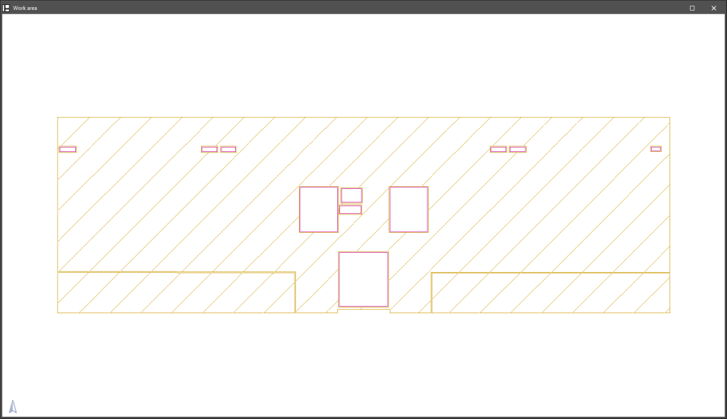
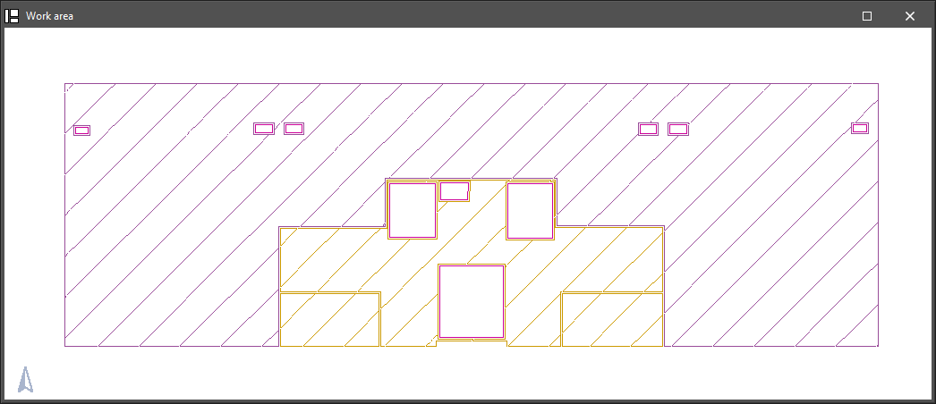
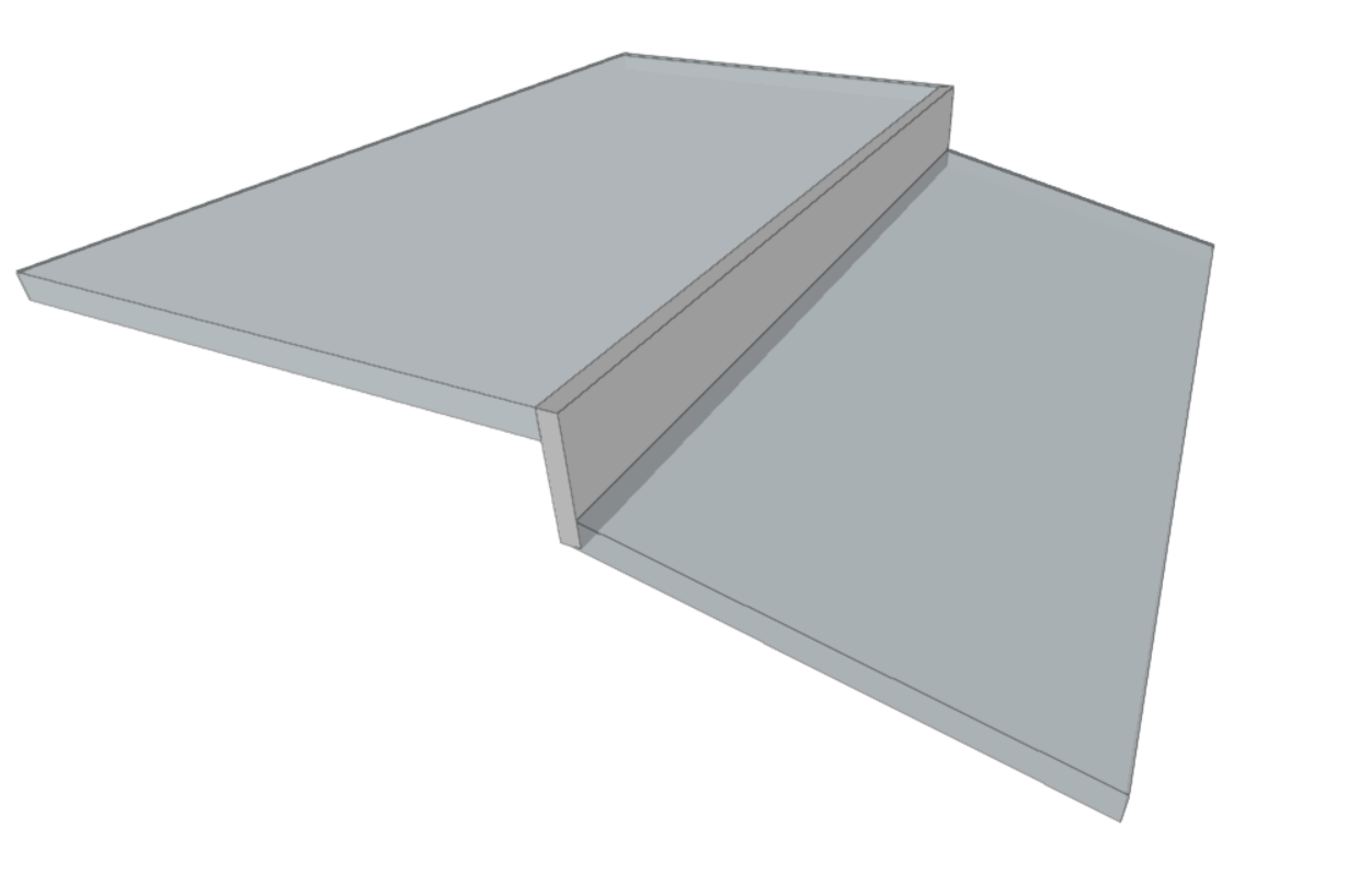
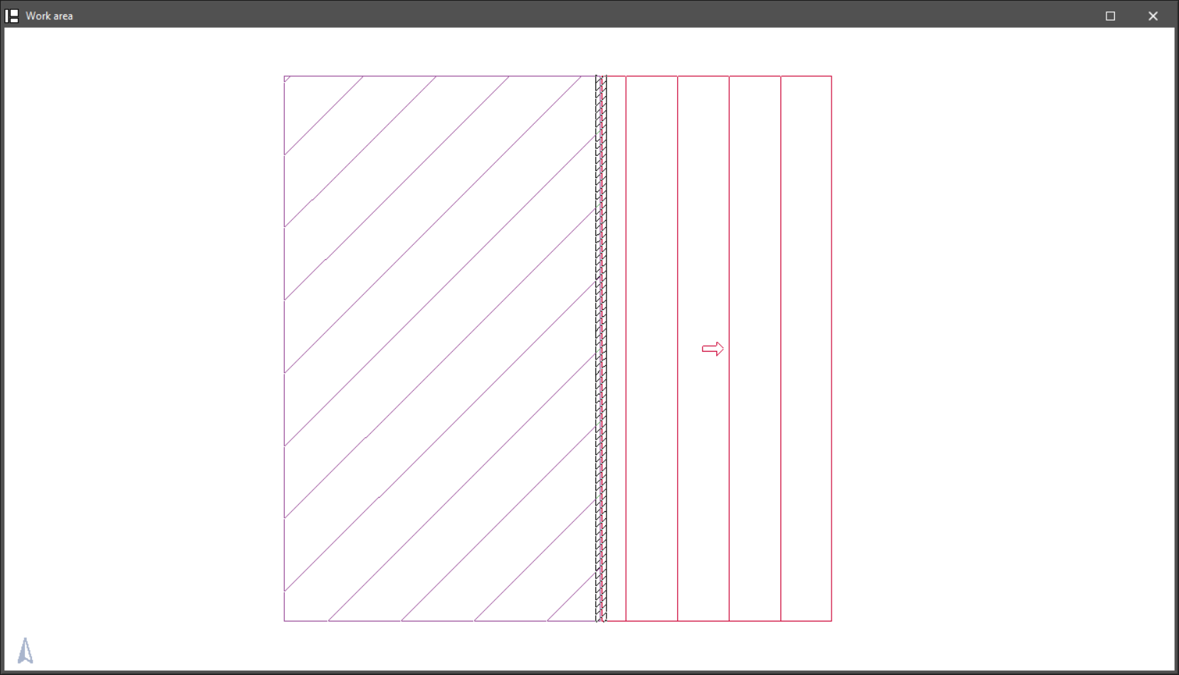
Closing elevation changes
This option allows you to create a closure at the elevation changes previously generated at the boundary between two floor slabs on the same storey, after using the "Insert elevation changes in horizontal partitions" or "Insert elevation changes in roofs" options.
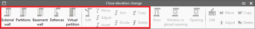
The closing of gaps can be categorised as any of the types of walls and partitions and uses the same editing tools:
- External wall
- Partitions
- Basement wall
- Defences
- Virtual partition
- Edit
- Move
- Adjust
- Invert
- Join
- Divide
- Copy
- Delete
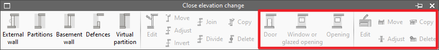
Furthermore, in the menu accessible via this option, you can insert gaps in the level transitions defined in the model. This menu provides the editing tools for these levels:
- Door
- Window or glazed opening
- Opening
- Edit
- Move
- Adjust
- Copy
- Delete
Elevation changes are shown on the floor plan using a hatched pattern.
Columns
The "Columns" menu allows you to add and edit rectangular or circular columns in the model.
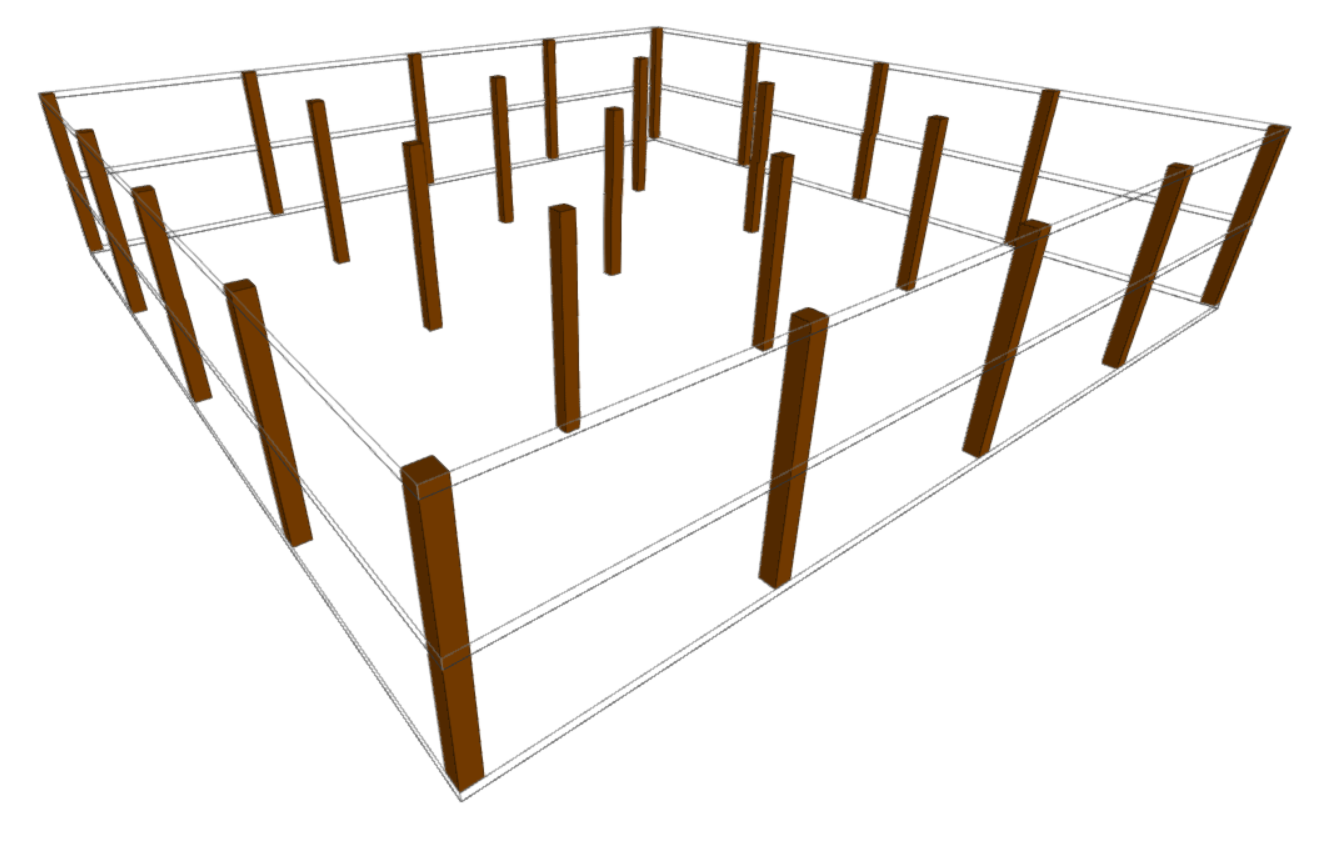
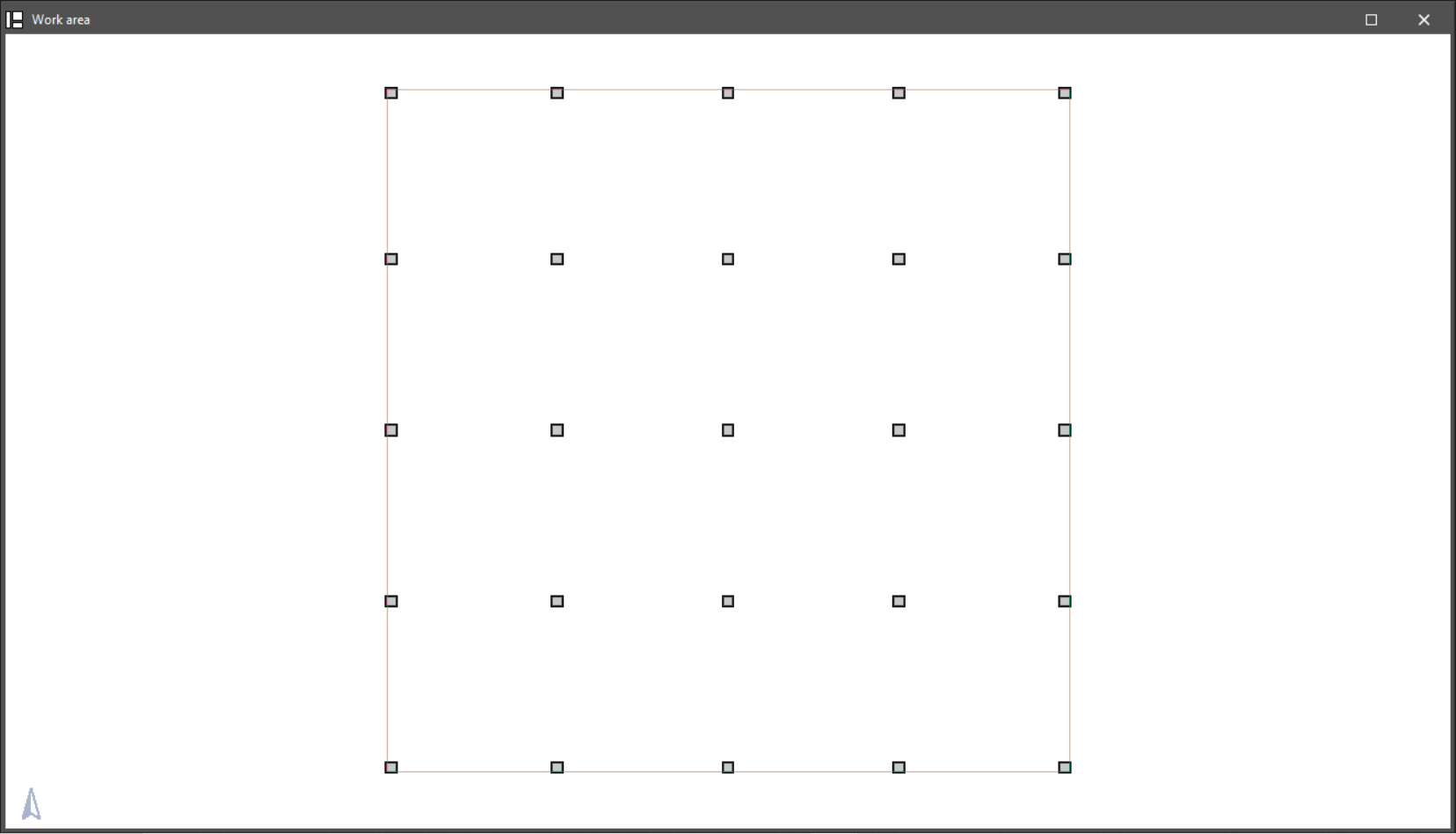
The option available for inserting columns is as follows:
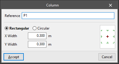
- New:
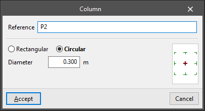
Add a column after defining the following parameters:- Reference
- Type selection:
- Rectangular
- Width X
- Width Y
- Circular
- Diameter
- Rectangular
- Insertion point (centre, sides or corners)
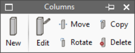
The options available for editing pillars are as follows:
- Edit
Edits the reference, type and characteristics of the selected abutment. - Move
Moves the selected column. - Rotate
Rotates the selected column 90 degrees. - Copy
Copies the properties from one column to another. - Delete
Deletes the selected pillars.
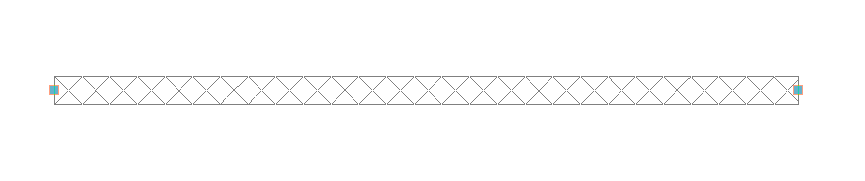
Thermal breaks
The "Thermal breaks" menu allows you to add and edit this type of element in the model. A thermal break is an element designed to reduce the flow of heat through a specific area, a specific edge or a specific structural junction in the building, thereby preventing the formation of a linear thermal bridge.
The tools available in this menu are as follows:
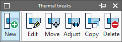
- New
Inserts a new thermal break into the workspace. - Edit
Edits the properties of a thermal break. - Move
Moves a thermal switch. You can move it parallel to its current position or move one of its ends. - Rotate
Rotates the position of the thermal break relative to the reference line. - Copy
Copies the type and description from one thermal break to another. - Delete
Deletes thermal breaks.
Thermal breaks are represented in the workspace as linear elements covered by a striped pattern and are placed in the areas where heat flow needs to be reduced.