Editing lateral and roof purlins
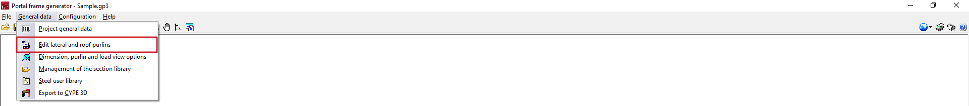
In the "General data" menu at the top, there is an "Edit lateral and roof purlins" option, which can be used to define, check and design steel purlins on the roof and/or on the sides of the structure.
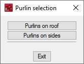
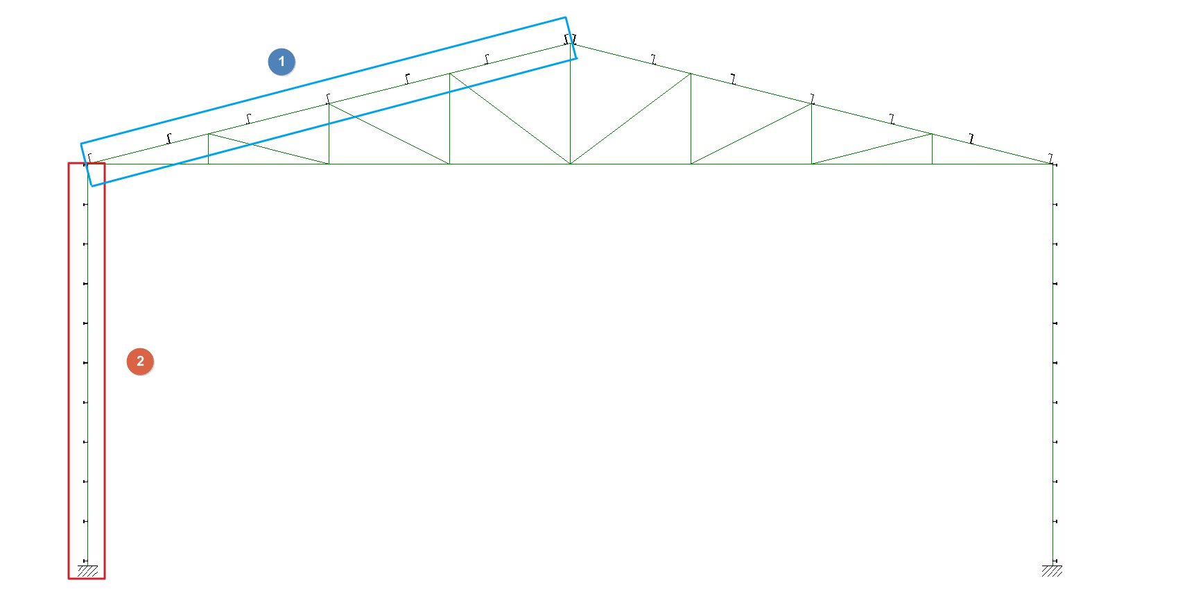
Purlins can be inserted in the roof sides of all inserted portal frames (1) with the "Purlins on roof" option, and purlins on both façade sides (2) with the "Purlins on sides" option.
Selecting one of these options opens the "Edit roof purlins" or "Edit lateral purlins" panel.
Editing purlins
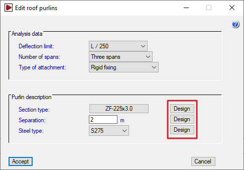
The options offered in each purlin editing panel are as follows:
- Analysis data
- Deflection limit
Sets the maximum deflection allowed for the purlins according to the light they cover. By default, a deflection limit of L/250 is taken. It is also possible to indicate "Unlimited" to set no deflection limit. - Number of spans (One span / Two spans / Three spans)
Number of spans spanned by the purlins in continuity and considered in the design model. The program checks the purlin in all possible positions and retains the most unfavourable results.
This parameter does not refer to the number of spans in the structure, which is defined in "General project data". However, users must take into account that if the different purlin sections are linked by overlapping between the portal frames, there is a continuity in the transmission of forces, so that the purlin should be analysed with the same number of spans as the complete structure. - Type of attachment (Non-collaborating roof / Hook fixing / Rigid fixing)
This is used to indicate the type of fastening of the roof cladding or side facades to the purlins. This defines the loads with which the purlins must be checked. The choice of fastening case must ensure that the construction reality corresponds to the selected design model.- Non-collaborating roof
The roof or façade does not collaborate with the purlins in their support, so they must be analysed with the full load, inside and outside the roof or façade drawing and including torsion. - Hook fixing
The roof or façade is assumed to be infinitely rigid in its drawing. The purlins support bending and shear only in the drawing perpendicular to the roof or façade, plus torsion (warping is neglected). - Rigid fixing
The roof or façade is assumed to be infinitely rigid in its drawing and also prevents the purlins from twisting. The purlins only support the bending and shear in the drawing perpendicular to the roof or façade, and there is no torsional moment. The deflected bending is also not considered for sections that are not on major axes.
- Non-collaborating roof
- Deflection limit
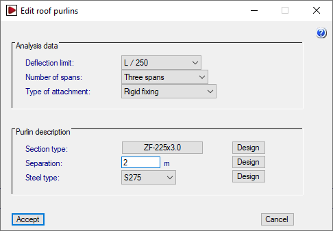
- Purlin description
- Section type
Selects the purlin section by accessing the "Section selection" window. - Separation
Enters the value of separation between the purlins. - Steel type
Used to select the type of steel from those available according to the standard chosen in "Configuration". The steels created from the "User steel library", under "General data", are also available for selection here.
- Section type
| Checks carried out on the purlins depending on the type of fixing | Non-collaborating roof | Hook fixing | Rigid fixing |
| Bending and shear in the drawing of the roof or façade | Yes | No | No |
| Bending and shear in the drawing perpendicular to the roof or façade | Yes | Yes | Yes |
| Torsional moment | Yes | Yes | No |
| Lateral buckling of the outer wing | Yes | No | No |
| Lateral buckling of the inner wing | Yes | Yes | No |
Section selection options
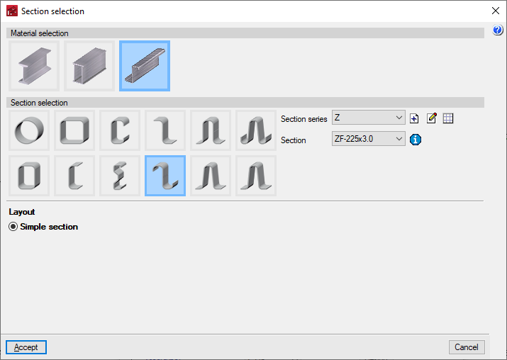
Click on the button available in the "Section type" to access the "Section selection" window.
In the upper part of this window, the material of the purlins is selected, whether they are rolled steel profiles, reinforced rolled steel profiles or formed steel sections. Below, the type of section is selected from among those available, and its layout is defined in the lower part.
The drop-down "Section series" and "Section" menus can be used to select the desired series and, within this series, the section of the series to be used in the definition of the purlins.
The management of the available section series is carried out by means of the options located next to the drop-down menus. From here, predefined section series can be imported, manufacturer catalogues can be imported, or section series can be created and defined manually, as well as importing and exporting the information to files on disk. The program will also display the predefined section series or manufacturer catalogues imported via the "Section library management" option in the "General data" menu.
Finally, next to the "Section" drop-down menu, the "Properties of the selected section" can be consulted.
Purlin check
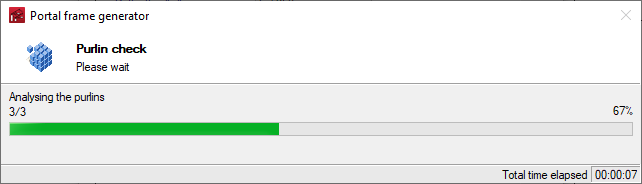
When accepting the purlin editing panel, the program will check the sections according to the data and analysis conditions that have been defined.
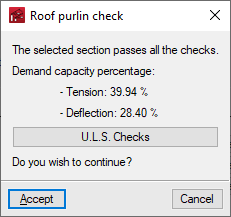
At the end of this analysis process, a dialogue box is displayed with the percentages of utilisation at tension and at deflection.
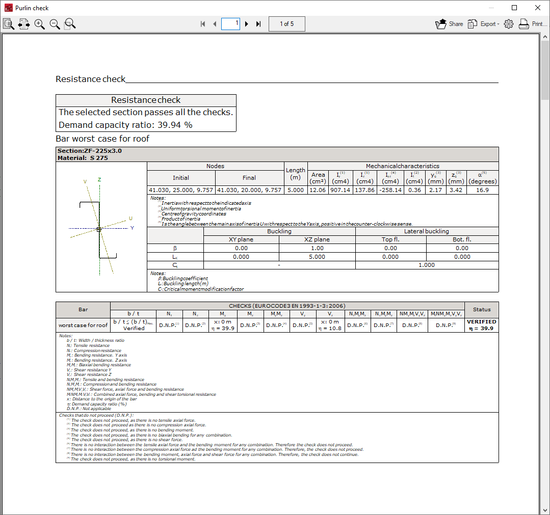
It is also possible to obtain a report with the checks carried out by clicking on the "U.L.S checks" option. The program can print this report directly or generate HTML, PDF, TXT, RTF or DOCX files.
Purlin design
The three "Design" buttons on the right side of the purlin editing panel can be used to optimise the selected section and the separation between purlins:
- The design carried out with the first button (next to "Section type") keeps the selected purlin separation and steel type, and tries to find the section of the series that complies with all the checks.
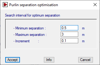
- The design carried out with the second button (next to "Separation") keeps the selected section and steel type, and tries to find the optimal purlin separation that complies with all checks. The optimum separation is found by starting with the "Maximum separation" and reducing it by the value of "Increment" until the "Minimum separation" is reached.
- Finally, the design performed with the third button (next to "Steel type") keeps only the selected steel type, and tries to find together the section and the optimal purlin separation that fulfils all the checks. For each section, the optimum separation is searched for by starting with the "Maximum separation" and reducing it by the value of "Increment" until the "Minimum separation" is reached.
At the end of the design process, the program displays the following:
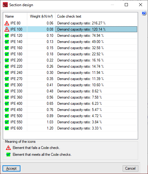
- In the case of section design, a report is displayed with the compliance status for each of the sections of the series for the selected separation, indicating its name, weight and the demand capacity ratio percentage.
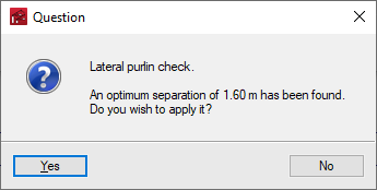
- In the case of a separation design, a dialogue box opens with the optimum separation found for the selected section, which can be applied or not by accepting the panel.
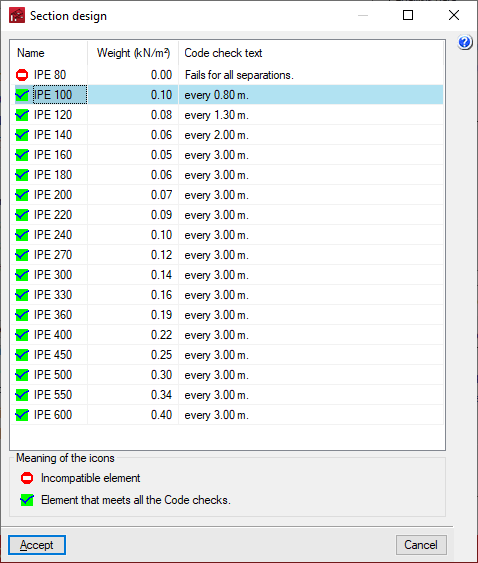
- In the case of a joint section and separation design, a report is displayed with the required gap for each section of the series, as well as its compliance status, name and weight.
In the displayed section lists, the desired section can be selected by double-clicking on it with the left mouse button. Subsequently, the window must be accepted to apply the changes.