
Exporting to CYPE 3D
In the “General data” menu at the top, there is the “Export to CYPE 3D” option, which allows users to configure the generation parameters of the portal frame structure exported from Portal frame generator to the CYPE 3D program.
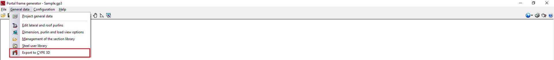
When using this option, the program will first perform a check of the purlins with the defined data. Then, should the user wish to continue, it will open the "Options for exporting to CYPE 3D" window.
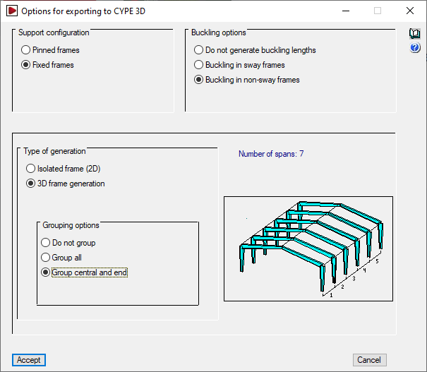
Options for exporting to CYPE 3D
In this window, the following aspects must be configured:
- Support configuration
Sets the type of external bracing to be generated at the foot of the columns of the portal frame in CYPE 3D. The selection of the support type will also influence the determination of the buckling lengths.- Pinned frames
An "Articulation" type external connection shall be generated at the foot of the columns. In the generation of buckling lengths, lintels with twice the inertia of the columns shall be assumed. - Fixed frames
An "Embedding" type external connection shall be generated at the foot of the columns. In the generation of buckling lengths, lintels with the same inertia as the columns shall be assumed, and an "Articulation" external connection shall be generated at the foot of the columns. In the generation of buckling lengths, lintels with twice the inertia of the columns shall be assumed.
- Pinned frames
- Buckling options
Sets the buckling lengths assigned to the bars generated in the export. The program shall generate the buckling lengths for all the bars of the portal frame in case of using the "Buckling in sway frames" or "Buckling in non-sway frames" options. The building shall be considered to be intraslational in the longitudinal direction. The difference between translational and intraslational portal frames affects the analysis of the buckling lengths in the drawing of the portal frame and only the supports.- Do not generate buckling lengths
If this option is selected, buckling coefficients equal to one shall be taken. - Buckling in sway frames
Horizontal displacement of the column heads in the drawing of the portal frame is not prevented. This is the most frequent case and the one selected by default. - Buckling in non-sway frames
Horizontal displacement of the column heads in the drawing of the portal frame is prevented by the presence of diagonals or other bracing.
- Do not generate buckling lengths
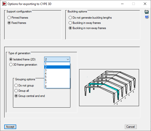
- Type of generation
- Isolated frame (2D)
A structure with a single isolated portal frame will be generated. The portal frame of the structure to be exported must be selected. - 3D frame generation
The complete structure with all frames, including the gables, is generated and exported.
- Isolated frame (2D)
- Grouping options
With this option, frames can be grouped in CYPE 3D, so that when the elements of a frame are modified, the elements of all the frames grouped with it are modified. The following grouping options are available:- Do not group drawings
Each frame in CYPE 3D is independent of the others. - Group all
All frames shall be grouped into a single group, including the gables or end frames which, in this case, shall have the same load as the central frames. - Grouping central and end
Two sets of frames are formed, one with the gables (the frames at the two ends of the structure), and one with all the frames in between. This is the default option.
- Do not group drawings
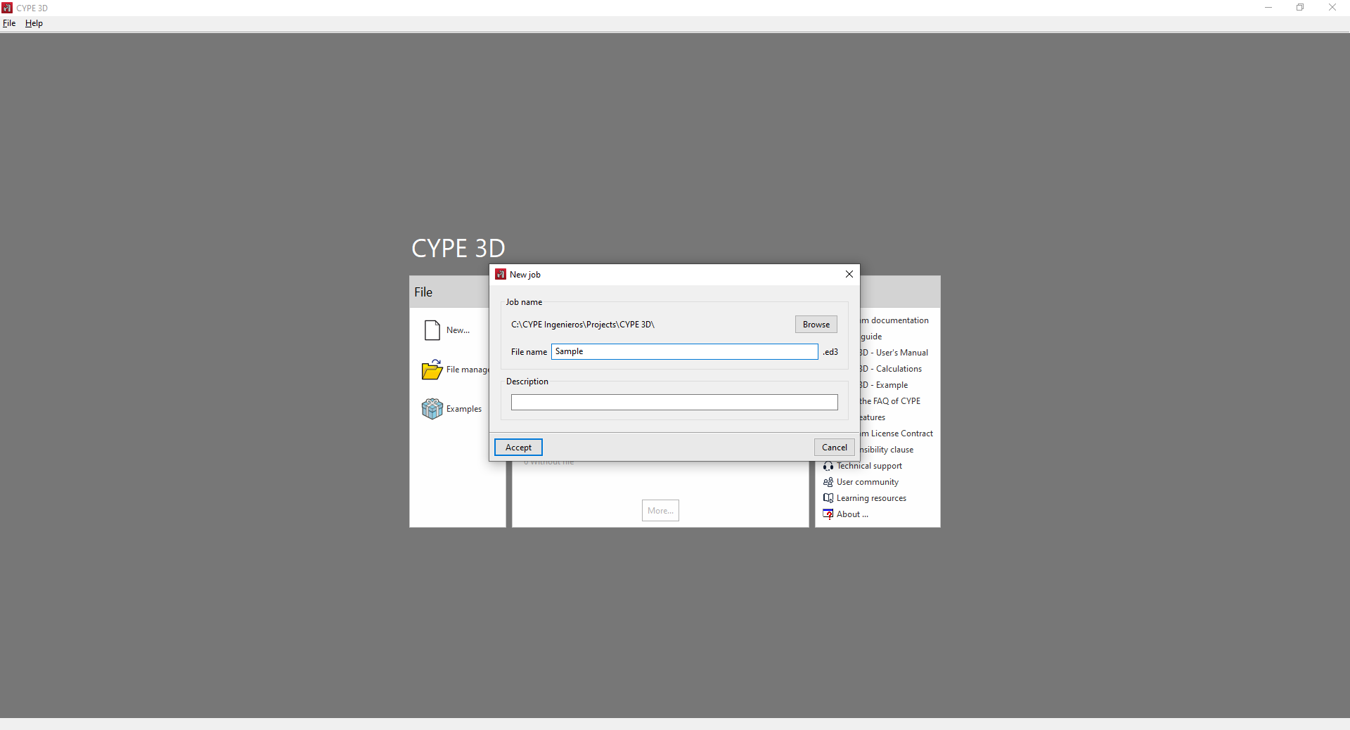
Creating a job in CYPE 3D
By accepting the "Options for exporting to CYPE 3D" window, the program will save the data of the Portal frame generator job, close this program and then automatically open the CYPE 3D application if it is installed.
A new job will be generated in CYPE 3D. The configuration of the general data must be checked, as well as the "Name" and "Description" of the job, together with the saving path of the CYPE 3D file.
Information generated in CYPE 3D
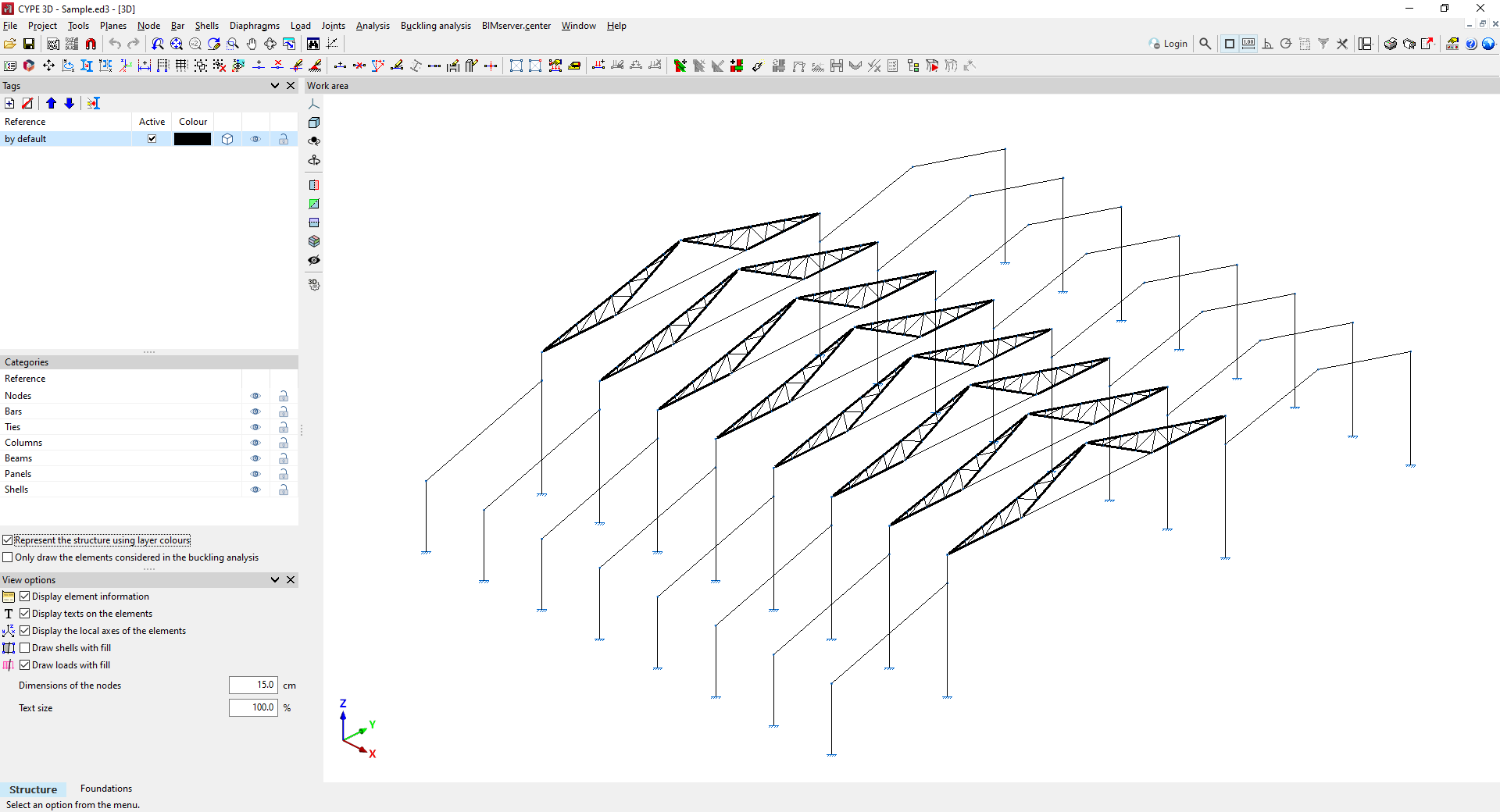
Finally, the program will open the CYPE 3D interface, where the portal frame structure generated in the new job can be viewed (which must be saved if it is to be retained), and work can continue with the CYPE 3D options for analysing the structure.
The information generated includes the following, together with the CYPE 3D options that allow it to be modified or revised:
- The bar geometry of the indicated portal frame or of the complete system of frames, which can be modified or completed with the options of the "Bar" menu. The type and cross-section of the portal frame sections must be defined from "Bar" by clicking on "Describe section", and new bars must be entered if necessary, such as the tie beams between frames. The geometry of the purlins is not exported, but their self-weight is.
- The necessary loadcases can be checked from "Job" by accessing "General data" and selecting "Additional loadcases".
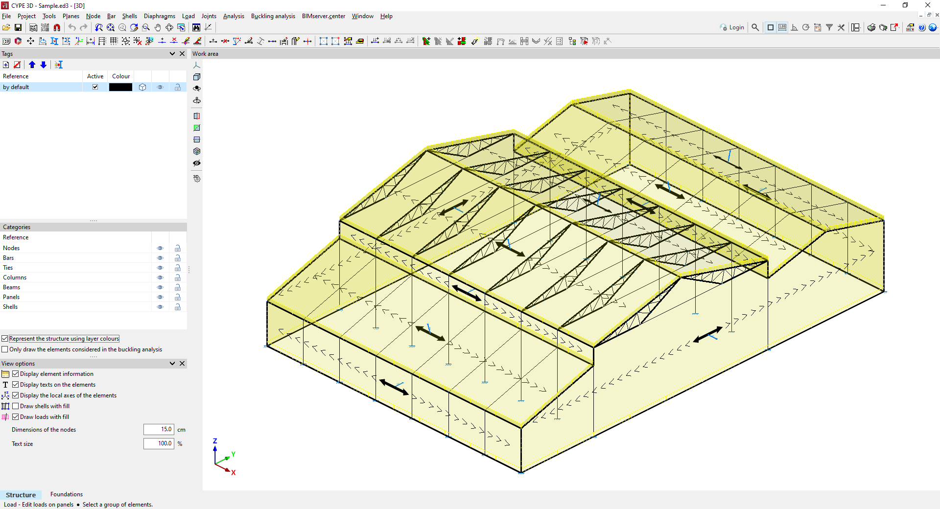
- If applicable, the necessary load panels that carry out the distribution of surface loads and that incorporate the information of the self-weight of the envelopes and purlins, and/or of the live load on the roof. They can be reviewed from the options related to the load sheets in the "Load" menu.
- Wind and snow surface loads can be reviewed from the options related to them in the "Load" menu.
- The grouping of frames, which can be reviewed under "Bar" in "Group/Ungroup";
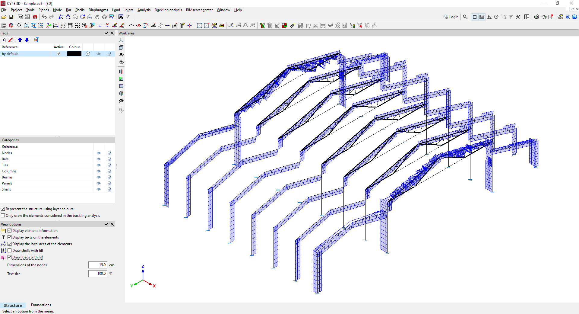
- The buckling lengths or buckling coefficients of the frame members, which can be reviewed under "Bar" by selecting "Buckling".
- The supports or external connections of the columns, which can be checked from "Node" by selecting "External connection".The information generated includes the following, together with the CYPE 3D options that allow it to be modified or revised:
| More information: |
|---|
| The data generated by Portal frame generator in CYPE 3D can be modified. The data for loads, geometry, node descriptions and bar checking parameters can be adjusted in CYPE 3D to adapt them to a situation similar to one that Portal frame generator cannot generate. |