
Entering and editing frames
Accessing the frame editing menu
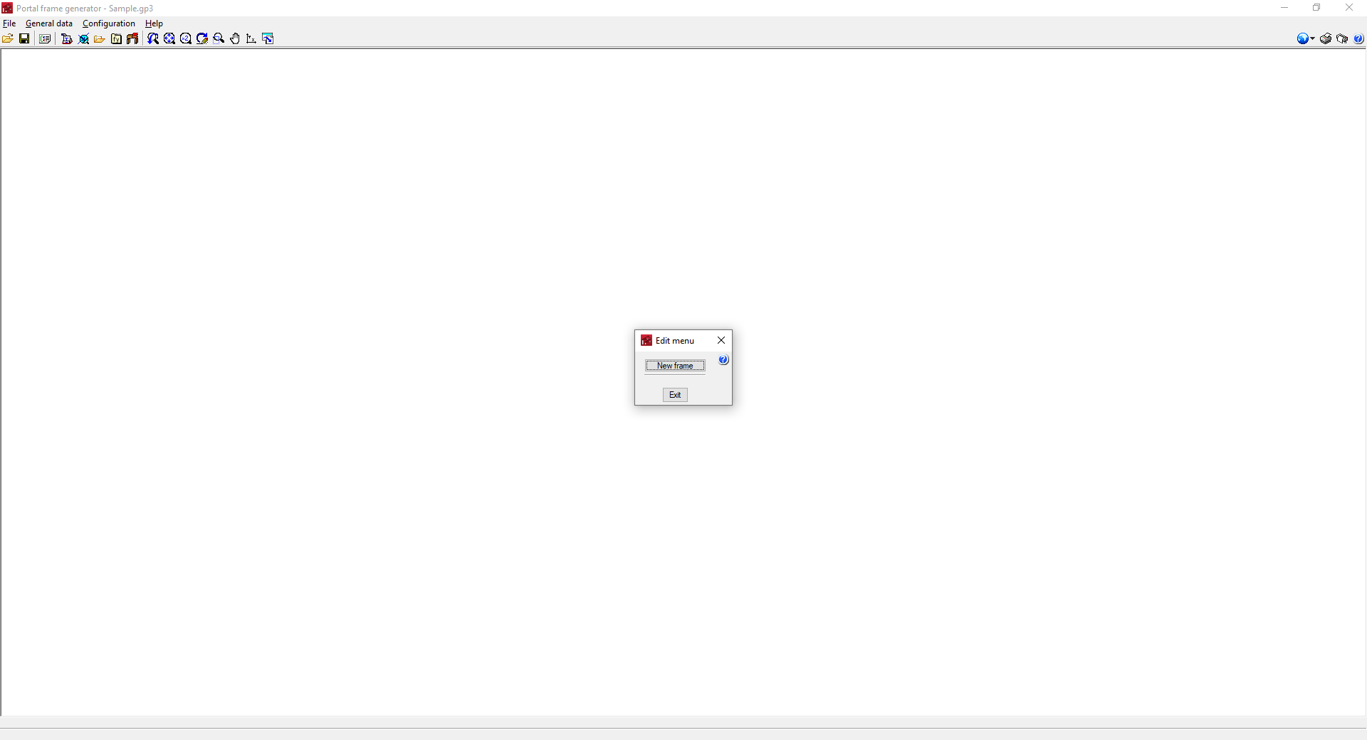
The "Editing menu" appears when clicking on the work area and includes the options that can be used to enter and define the geometry of the structure's frames. This menu varies depending on the area of the work area that is selected.
- When clicking on the empty work area before entering a frame, the "New frame" option will appear.
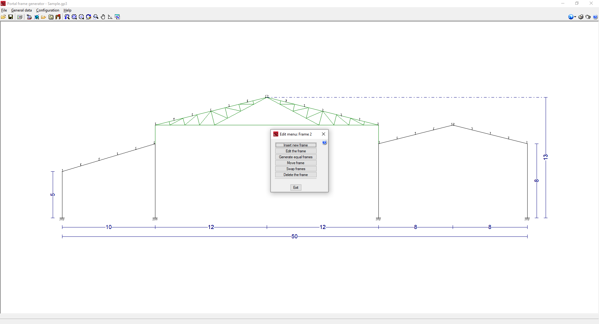
- When clicking on a previously entered frame, the following options will appear:
- Insert new frame
- Edit the frame
- Generate identical frames
- Move frame
- Swap frame
- Delete frame
- By clicking on the left or right side of the group of frames, the following options will appear:
- New frame
- Delete all frames
- Lateral wall
- By clicking on the top or bottom of the work area, the following options will appear:
- New frame
- Delete all frames
The use of the different options is detailed below.
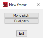
New frame/Insert new frame
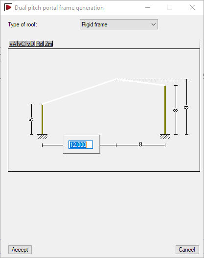
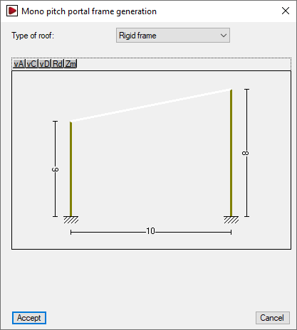
Creates a new frame by selecting "Mono pitch" or "Dual pitch" depending on the type of frame. Then, users can select the type of roof from the drop-down menu and edit the geometry of the frame by left-clicking directly on the dimensions shown in the editing window.
If one or more frame(s) have been previously inserted, the "Insert new frame" button creates the new frame to the right of the frame group.
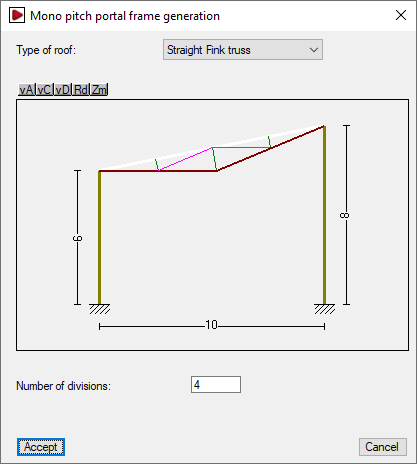
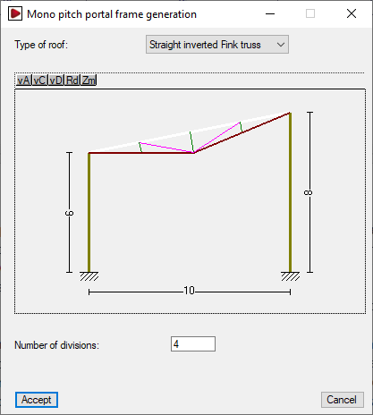
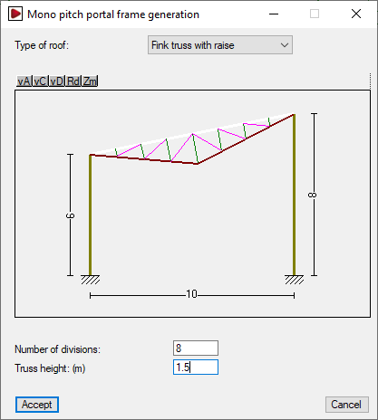
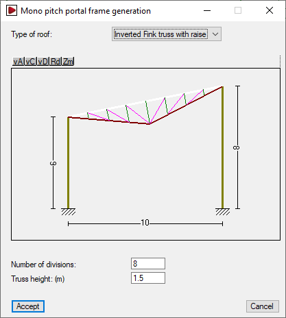
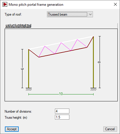
Available roof types for mono pitch frames
The types available for mono pitch frames and the parameters required for their definition are as follows:
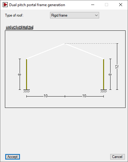
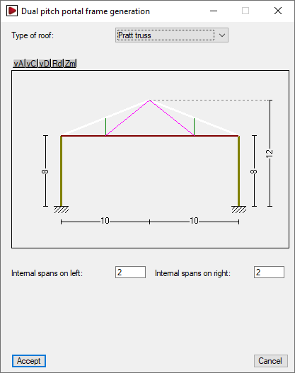
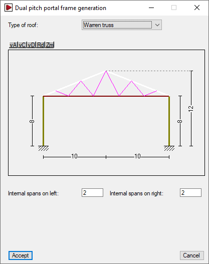
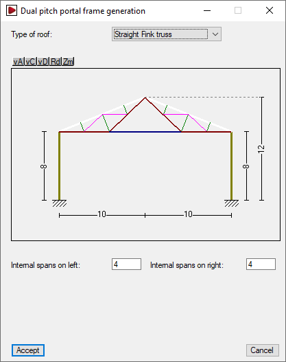
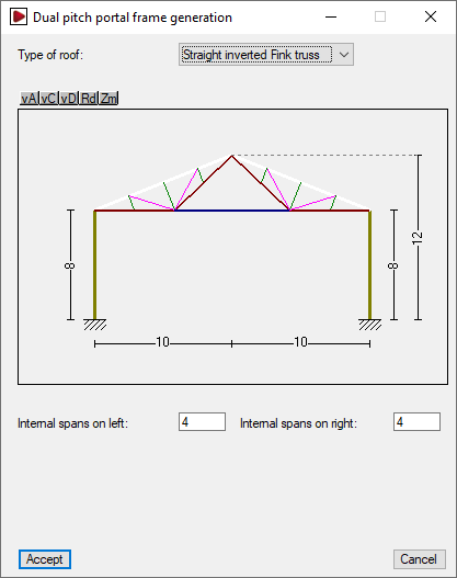
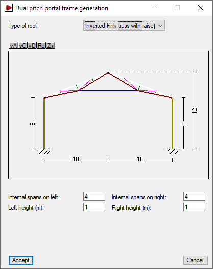
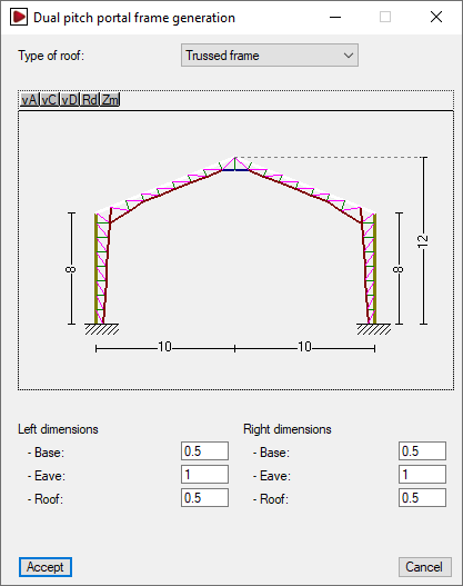
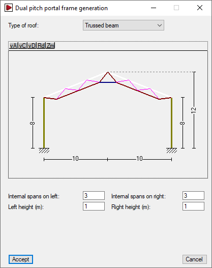
Roof types available for dual pitch frames
The types of dual pitch frame available and the parameters required for their definition are as follows:


Lateral wall
By clicking on the left or right side of the portal group, the "Lateral wall" option appears. This option is used to enter and define a perimeter wall to the structure on the selected side by activating the corresponding option.
Entering lateral walls can be used to adjust the generation of loads and buckling coefficients when exporting to CYPE 3D.
| Note: |
|---|
| To consider that the building has side cladding for generating wind loads and, therefore, is not an open canopy, the "With lateral wall cladding" option must be activated from "General data", "General data of the job". |
- With perimeter wall (optional)
Enters a perimeter wall on the selected side. The consideration of a perimeter wall allows the following parameters to be defined:- Wall height
Height of the perimeter wall. - Braces the column against buckling (optional)
Selecting this option means that the perimeter wall braces the columns against global buckling outside the portal frame drawing at the specified "Wall height", and against lateral buckling on both flanges. - Self-balanced (optional)
By selecting this option, the perimeter wall is assumed to be self-balancing, i.e. it supports by itself the wind load that is directly acting on it. Therefore, when exporting to CYPE 3D, the wind load below the specified "Wall height" is eliminated. If this option is kept deactivated, it is assumed that the wall transmits all the wind load received to the columns.
- Wall height

Frame editing options
The remaining frame editing options are as follows:
- Edit frame
Edits the selected frame by opening the editing window of the selected frame. - Generate equal frames
Copies the selected frame, which will be displayed in green, to the right of the last frame. The "Number of equal frames to generate" must be indicated in the dialogue box that appears below. - Move frame
This option only appears if more than one frame is generated. The selected frame, which will be displayed in green, can be moved to a new position. To do this, the program asks for the new position of the frame in the dialogue box that appears below. The numbering of the frame positions is from left to right. - Swap frames
This option only appears if more than one frame is generated. The selected frame, which will be displayed in green, can be swapped with another frame. To do this, the program asks for the new position of the frame in the dialogue box that appears below. The numbering of the frame positions is from left to right. - Delete frame
Deletes the selected frame. - Delete all frames
Deletes all frames.