
Shear walls
The CYPECAD "Shear walls" module analyses and designs reinforced concrete shear walls.
Shear walls are vertical elements of any cross-section, formed by multiple rectangles between each floor, and are defined by an initial level and an end level. The dimension of each side is constant in height, but its thickness can be decreased.
They are intended to be what their name implies: vertical supports of any shape that have to resist, as the main reason for their design, vertical loads and, fundamentally, horizontal loads.
Design premises for shear walls
- On plan, it is a figure formed by straight segments or sections that are joined at their vertices. Any shape can be created as long as it is a set of interconnected segments, whether they are an open or closed polygonal shape.
- The on plan form is constant over its entire height. One side cannot disappear, not even to become a floating column.
- It cannot overlap with another support, whether it is a column or a wall.
- The thickness of the sides may decrease for each floor over its full height.
- No openings are allowed. Doors cannot be fitted; they can only be joined at the ends by the elements of the horizontal slab at the level of each floor, such as a beam.
Discretisation carried out on shear walls
The model consists of triangular thick-sheet finite elements with six nodes (three vertices plus three midpoints of the sides) and six degrees of freedom per node. The triangles are always regular and equal on each floor.
Where it meets the floor, a bar is generated, with a width equal to that of the side of the shear wall and a minimum depth of 20 cm, or the depth of the corresponding slab. The nodes of this bar are those of the corresponding triangles and those of the bars coming from the slab, this bar being the one that connects the vertical elements with the horizontal ones, and naturally transmits the bending and torsional stresses between them.
Entering shear walls
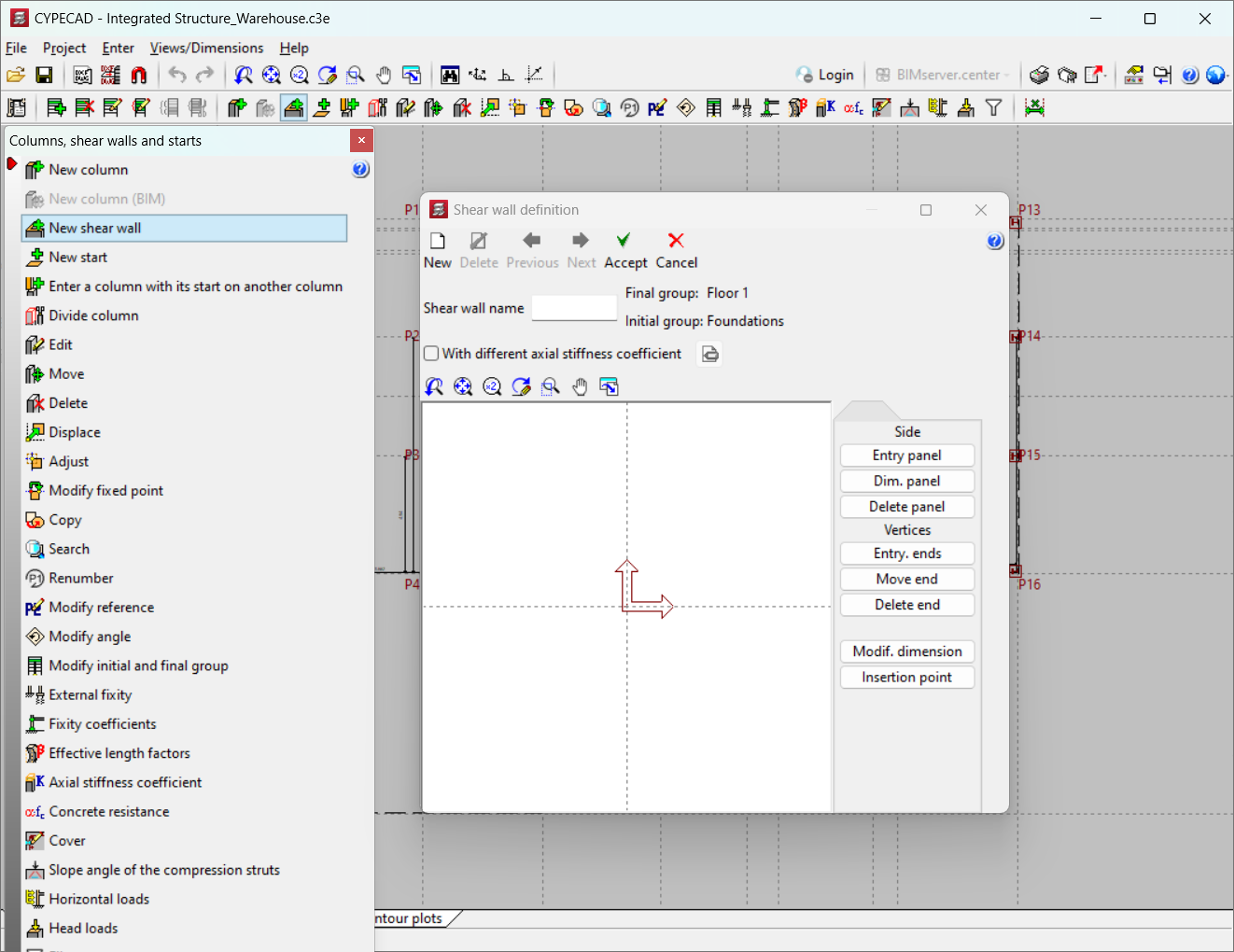
From "Columns, shear walls and starts" in the "Entry" menu of the "Column definition" tab, users can now enter new shear walls by selecting the "New shear wall" option.
A set of standard shear walls is first defined, specifying the following:
- Shear wall name;
- Initial and final group;
- Sides and vertices;
- Thicknesses on each floor to the left and right of the side axis.
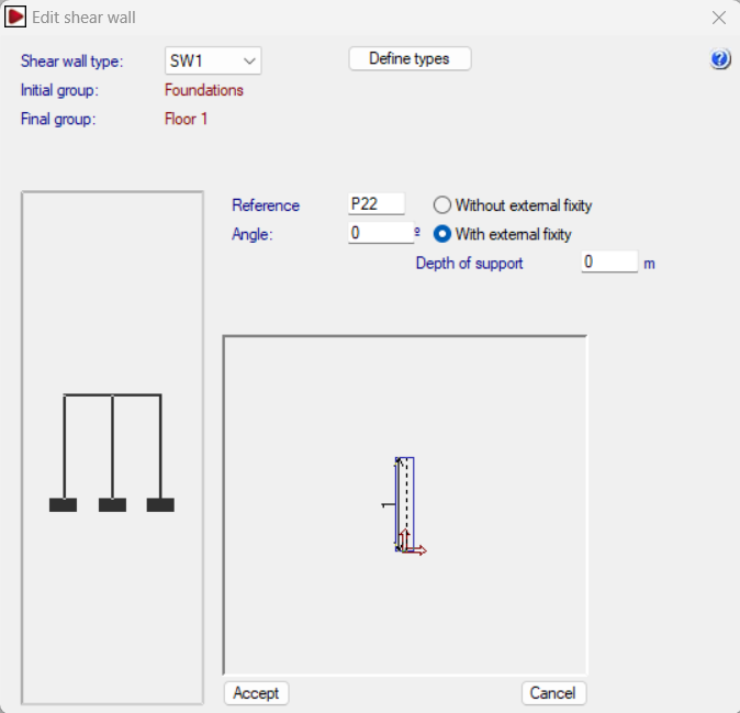
The first vertex defined is the fixed insertion point, although its position can be varied. The shear walls are then defined using the following parameters:
- Type of shear wall;
- Reference. Users can specify a reference that will appear on the drawings and reports;
- Angle. Allows users to modify the entry angle (from - 90º to + 90º);
- With or without external fixity. Start in foundation (with external fixity) or shoring (without external fixity) and up to the floor it reaches;
- Supporting edge;
- Define types. Allows users to modify the previously entered shear wall type and/or create new shear walls.
Reinforced concrete basement walls can be defined without lateral pressures, thus becoming load-bearing walls, as shear walls for resisting vertical and horizontal loads. They can replace the "Shear walls" that are defined in the "Column definition" option in the program, and they are also more versatile, as they can be joined with columns; and can be supported by columns, and embedded columns or columns that start at any level of the wall, with dimensions greater or less than the thickness of the wall; walls that start and end on different floors can be joined together, etc.
Reinforcement criteria for shear walls
A shear wall is a surface element subjected to the 6 corresponding forces. It shall have vertical and horizontal reinforcement on each face which shall be constant on each floor in order to be constructive. It may be different on each side or section.
The reinforcement is obtained from sequentially ordered tables. The program checks the reinforcement with the existing forces at each node so that the reinforcement is increased until all the nodes of each face for each reinforcement position are compliant.
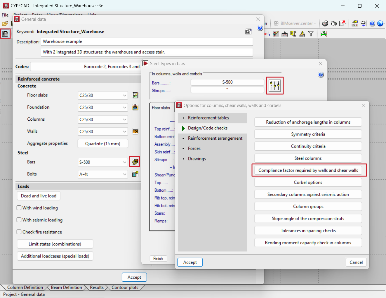
The compliance of all nodes can be reduced to a certain % defined in the program options, using what we have called "compliance factor" ("General data", "By position" option in the "Steel types in bars" section, "Options for columns, shear walls, walls and corbels" option, "Compliance factor required by walls and shear walls").
From the Edit reinforcement dialogue box that appears when selecting the "Edit" option in the "Columns/Shear walls" menu (from the "Results" tab), the placed reinforcements may be viewed on the shear wall together with the non-compliant nodes in red. By clicking on the "Show additional reinforcement" option in the aforementioned dialogue box, the red nodes change colour and can be selected, in which case, a report will be displayed on the screen, showing the non-compliant reinforcement (vertical or horizontal left or right, or transverse), the ratio factor of each reinforcement (ratio between the required amount and the amount provided) and a proposal for the reinforcement.
Reinforcement tables and analysis options for shear walls
When "By position" is selected in the "General data" screen, a window opens in which, in addition to choosing different types of steel for the referenced elements, users can also edit, modify or add reinforcement tables and analysis options.
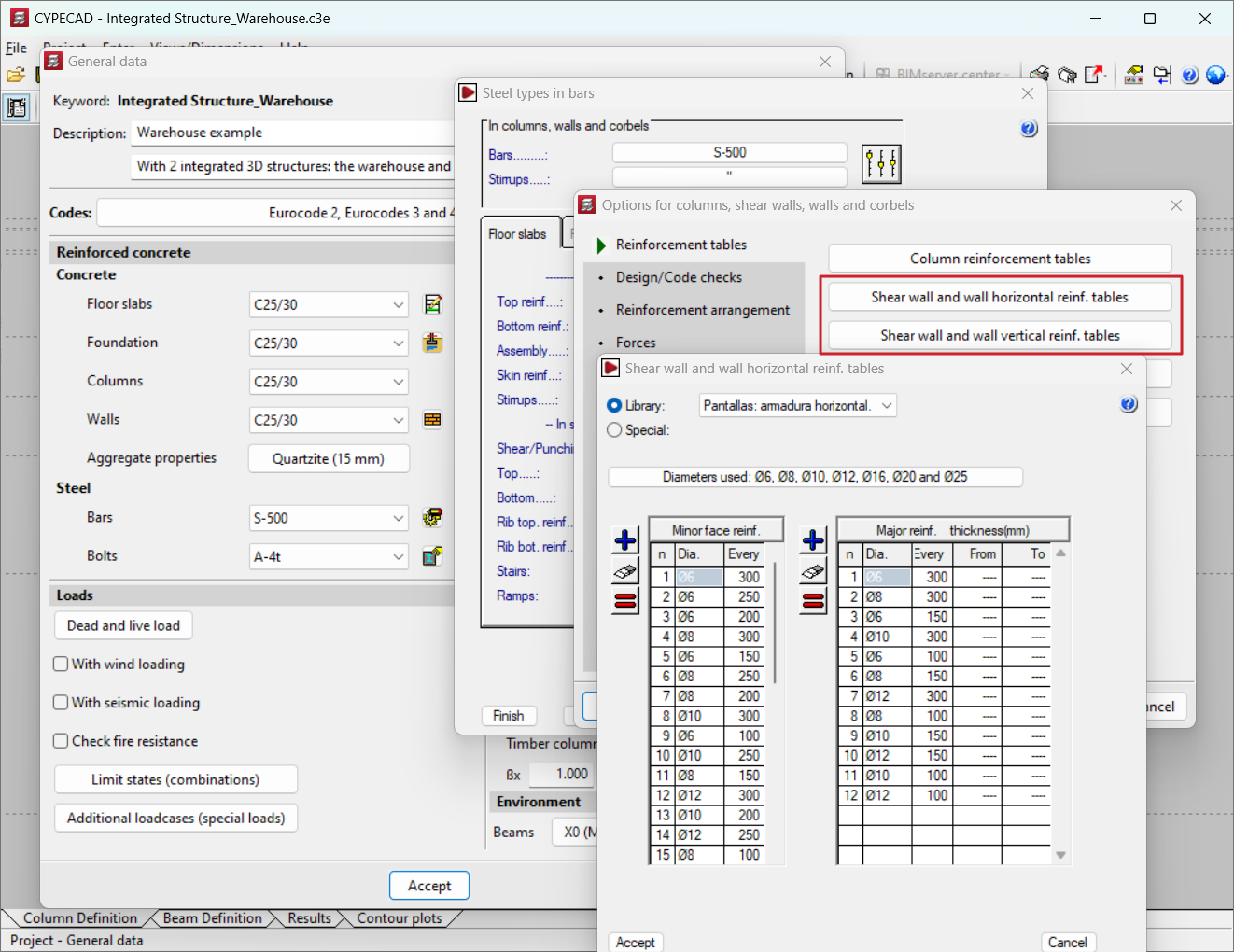
The following reinforcement tables can be edited for the shear walls:
- Shear wall and wall horizontal reinf. tables. Allows users to check and modify the horizontal reinforcement for shear walls and walls (the table is the same for both elements). The program will analyse the horizontal reinforcement required on both sides of the shear wall for each floor, so there may be different reinforcements between them. Therefore, a series of reinforcements can be configured for each face with minor reinforcement ("Minor face reinf.") on each face with major reinforcement ("Major reinf. "). If a symmetrical reinforcement on two faces is desired, the table must be modified, leaving a single and identical reinforcement in "Major reinf." for each sequence defined in "Minor face reinf.".
- Shear wall and wall vertical reinf. tables. Allows users to consult and modify the vertical reinforcement for the shear walls. This works in the same way as in the previous section.
All reinforcement tables have similar operating aspects, such as: "Library", "Special" or "Diameters used".
Checking and designing shear walls
Once the state of the forces has been determined and the forces have been calculated for each combination, the forces and deformations of the concrete and steel for the reinforcement set out in the tables are checked on each reinforcement face both vertically and horizontally, increasing sequentially until a certain reinforcement complies with all the combinations. The reinforcement is also checked in the transverse direction, calculating reinforcements if necessary. This process is repeated for each side of the shear wall.
Following the applicable standard, checks are carried out on minimum and maximum ratios, minimum and maximum spacings, as well as dimensional checks of the sides (the width of a side is greater than five times its thickness), because if this is verified, the program displays an informative message, and the imposed limits for columns are applied to it. The slenderness limits are also checked on shear walls, for each side, and a message is displayed if it is exceeded.
Finally, users can check the reinforcement obtained as well as the design errors on each shear wall. If the reinforcement or thickness varies, a check is carried out. The program will issue the relevant error messages. If the sections vary, the new reinforcement can be redesigned, resulting in the new reinforcement, and the necessary checks can be carried out.
Results output
- Diagrams of normal and shear stresses can be checked for the full height of the shear wall for each calculated combination, as well as displacement diagrams for the defined loadcases. The diagrams are shown in colour and scaled according to proportional values, with minimum and maximum values shown.
- The reinforcement can be checked and modified at the designer's discretion, as can the thicknesses, which are shown in red when they are not compliant. The compliance factor in % of the reinforcement in place and the areas to be reinforced, if any, can also be consulted. A reinforcement report can also be obtained.
- The program can list the worst case forces in the span and the forces by loadcase of the resultant.
- The detailing of the shear walls can be obtained, including elevation of the lengths and a table with the lengths of all the bars.
User license
For CYPECAD to be able to analyse and design reinforced concrete shear walls, the user license must include the "Shear walls" module in addition to CYPECAD,
Other features
To access other features offered by the program, several modules can be found on the "CYPECAD modules" page.