Stairs
General information
The CYPECAD "Stairs" module analyses and designs the reinforcement of staircase slabs as isolated elements of the structure. Depending on the geometry, type and layout of the supports and the gravity loads applied, the program determines the reactions on the main structure, which are translated into linear and surface loads (for the screeds) in the dead loads and live loads.
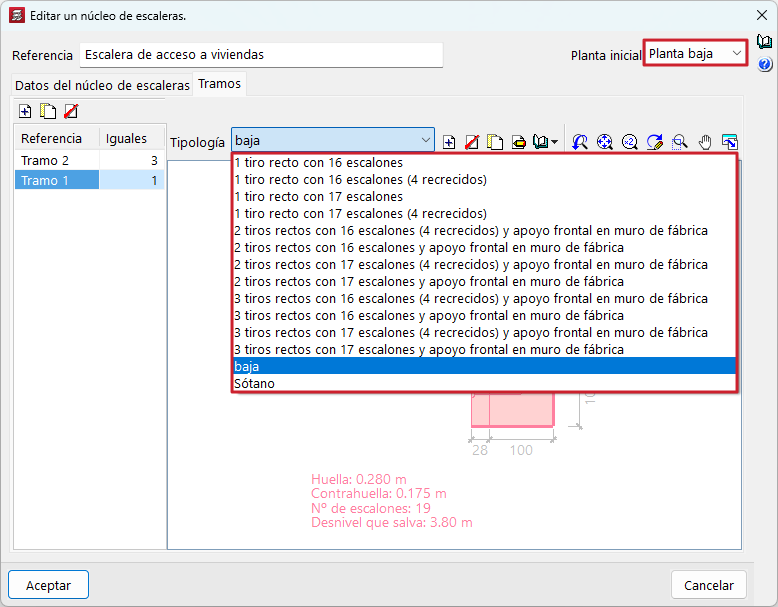
The program solves stair cores whose flights between floors are formed by parallel or orthogonal staircases of the following types:
 Straight flight
- Two straight flights with half turn landing
- Three straight flights with quarter turn landings
- Two straight flights with quarter turn landing
- Two consecutive flights with intermediate landing
- “n” straight flights with half turn landings
- “n” straight flights with quarter turn landings
 Straight flight
 Two straight flights with half turn landing
 Three straight flights with quarter turn landings
 Two straight flights with quarter turn landing
 Two consecutive flights with intermediate landing
 “n” straight flights with half turn landings
 “n” straight flights with quarter turn landings
In CYPECAD, a stair core is understood to be the set of flights of stairs between floors that define the vertical circulation of a certain area of a building. A flight of stairs is the inclined part of a staircase formed by a continuous succession of steps that covers the difference in level between two horizontal planes. The intermediate horizontal plane between two consecutive flights is called the landing.
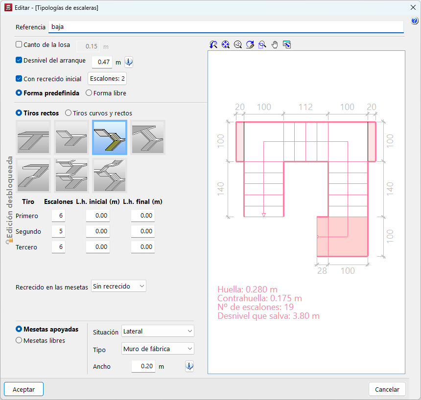
Data entry
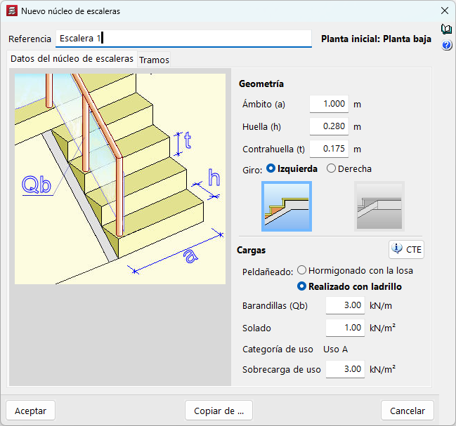
A stair core is defined by specifying the data common to the core (area, tread, riser, turn, last step formation, step material, railing loads, paving load and live load) and those particular to each span.
The choice of step, concrete with slab or made with bricks are the two most common ways of achieving this, influences the calculation of the permanent loads applied to the staircase and the quantity of concrete used in the construction of the staircase.
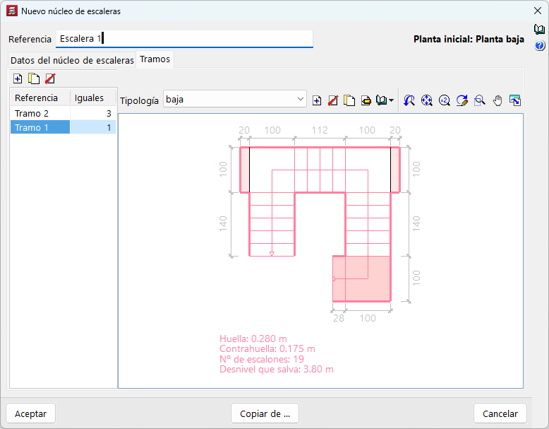
Staircase spans are the fractions of the stair core that go from one floor to another and may be composed of one or more flights. The characteristics defined in the spans may be different for each of them in terms of the slab depth, the slope of the start level, the initial screed, the layout of the flights and the plateaus, the number of steps in each flight, the width of the stair eye, the screed in the plateaus, the definition of the landing supports, etc.
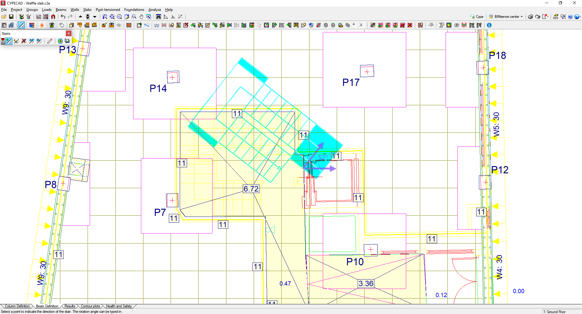
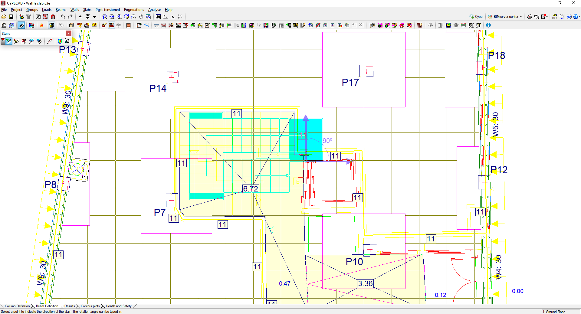
Positioning in the structure
To position the stair core in the structure, users simply have to indicate the start of the first span and a crossing point for the axis of the first flight of stairs. CYPECAD will enter the core with all the flights on the corresponding floors.
DXF or DWG snaps can be used to help locate these two points.
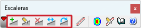
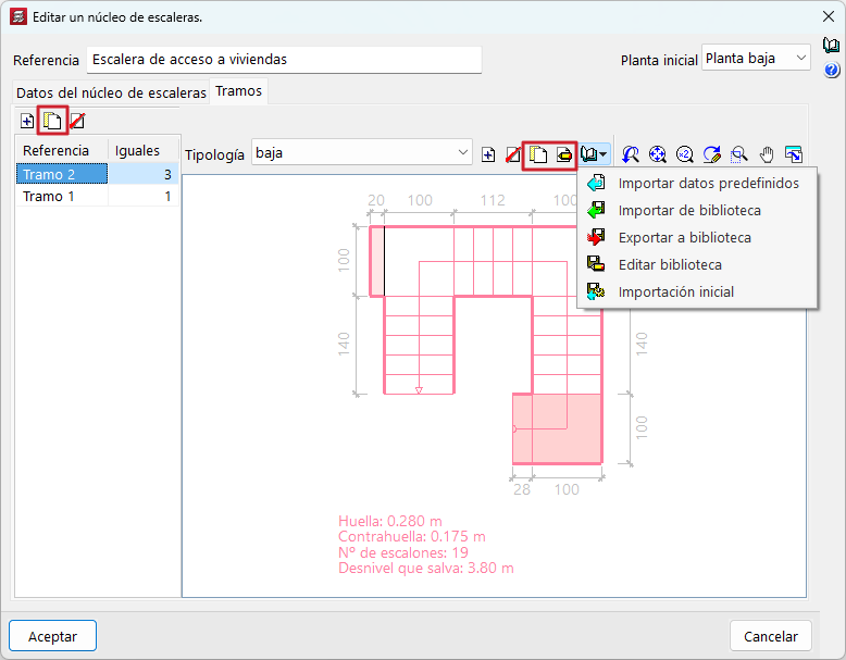
Options and tools to make data entry easy
The CYPECAD "Stairs" module has several editing tools (edit, delete, move, rotate), as well as tools that make it easier to enter stair cores in a structure.
The data of other stair cores of the same job can be copied in order to modify them and to enter new cores. The program has predefined staircase span types that can be used in the core to be defined with minor changes, and users can copy spans within the same stair core. There is also a library of stair core types that can be extended with user data for use in other jobs.
Analysis, results, reports and drawings
The program analyses the staircases individually and uses the finite element method, considering the two usual loadcases for analysing stairs: dead loads and live loads.
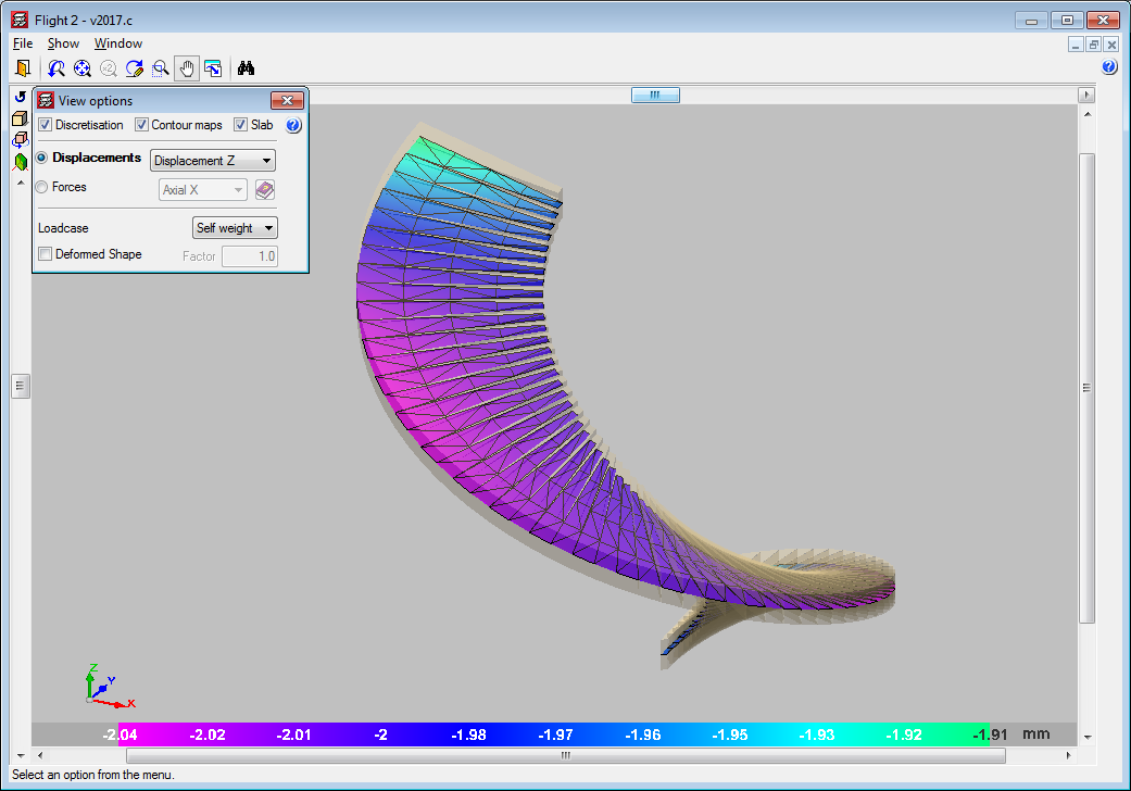
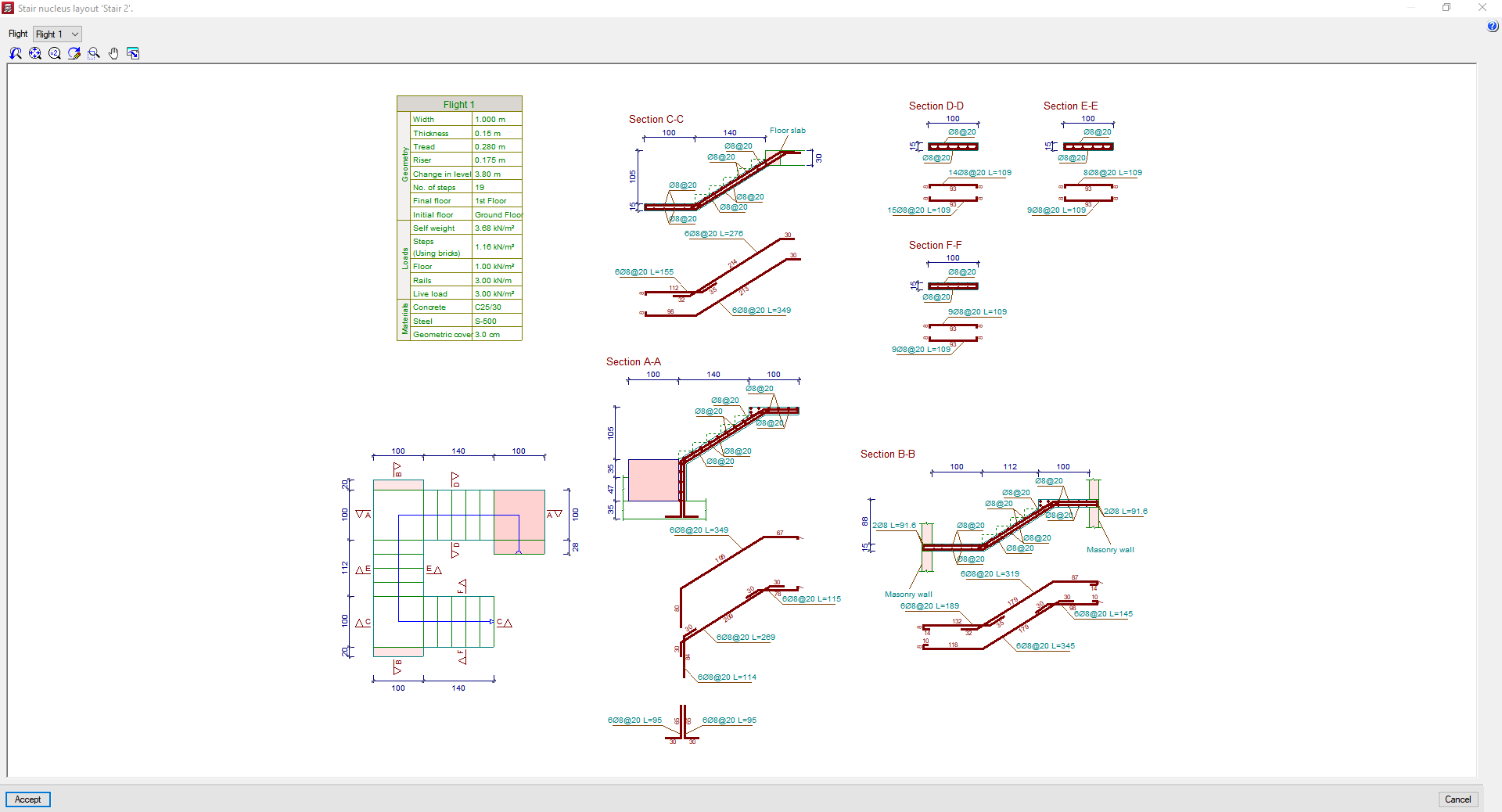
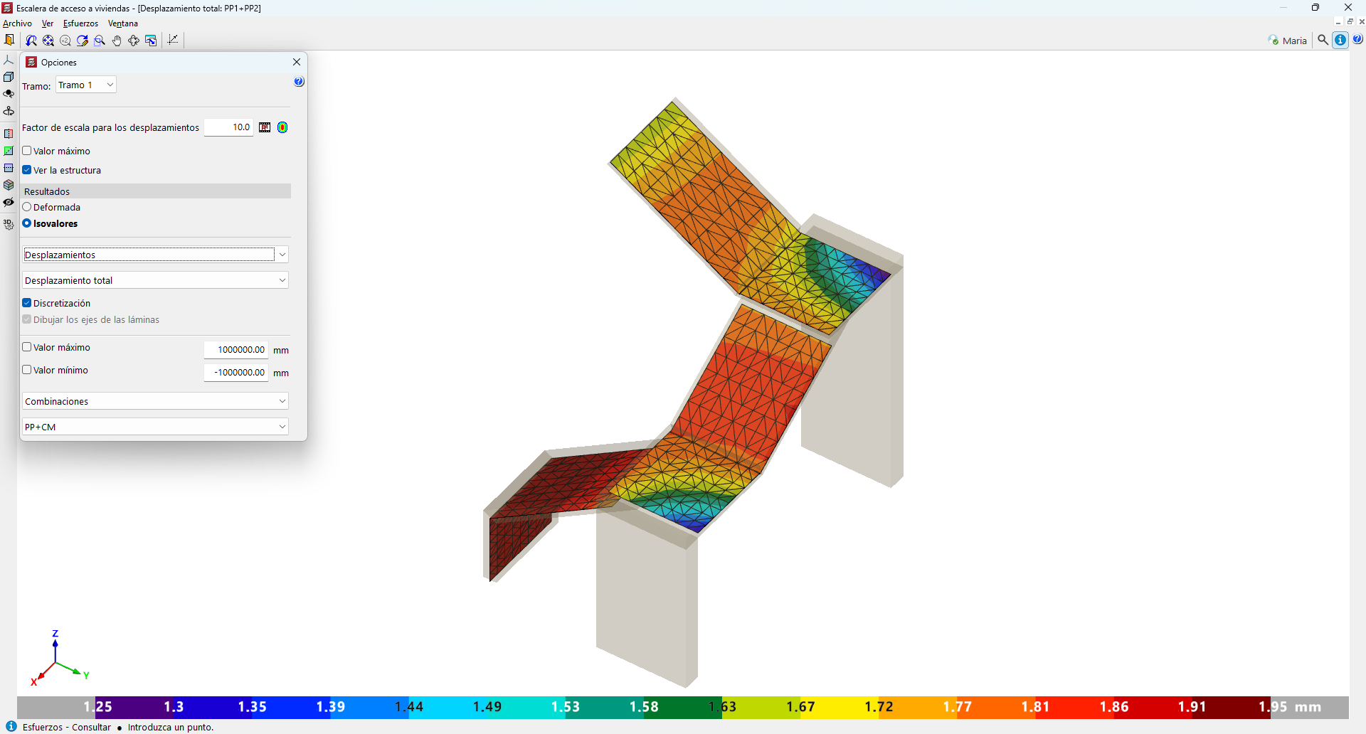
CYPECAD displays the reinforcement of each of the spans that make up the stair core on screen. Users can also consult the displacements, the forces and see the deformation of each span in a three-dimensional view.
The program analyses all stair cores when analysing the job, so that its reactions can be applied to the main structure. Therefore, the first thing the program analyses are the staircases.
Each stair core can also be analysed individually. To do this, simply ask the program to display its reinforcement, forces or displacements. If the job has not analysed or if changes have been made after the last analysis, the program will analyse the selected core.
The program displays a warning if changes are made to a stair core after the job has been analysed if these changes affect the value of the reactions, as users will need to reanalyse the job in order to consider the new reactions.
Reports of staircases that provide the general data of all the cores in the job (materials and code used), and the common data (geometries, loads, etc.) and particular data (reactions on the main structure, reinforcements, ratios and resulting forces in each section of the spans) of the spans of each of the cores can also be obtained.
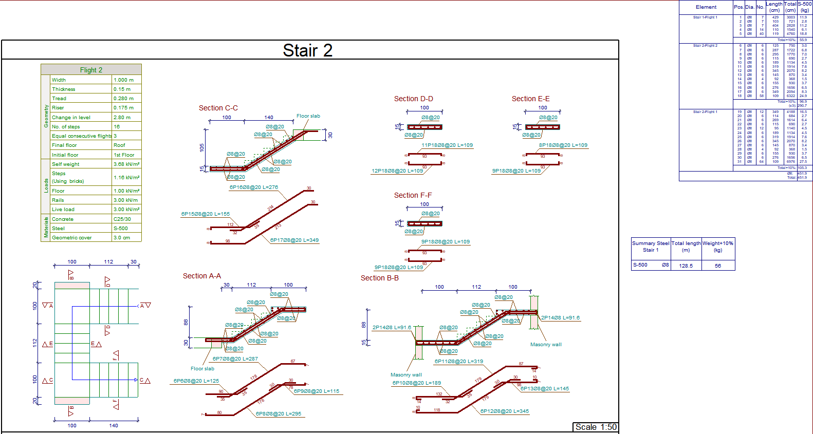
The drawings obtained by the program show all the information necessary to define the staircase exploded views: longitudinal and cross sections, tables of characteristics of each flight with its geometric data, loads and materials. The reinforcement quantities tables (by cores, spans and total steel summaries) are also included.
Configuration of the "Stairs" module (materials, reinforcement tables and analysis options)
The concrete used in the stair cores is the same as the one selected for the floor slabs, although the type of steel used in their reinforcement can be specific for stairs. The program has two reinforcement tables (longitudinal and transverse) exclusively for stairs that can be configured according to the user's preferences.
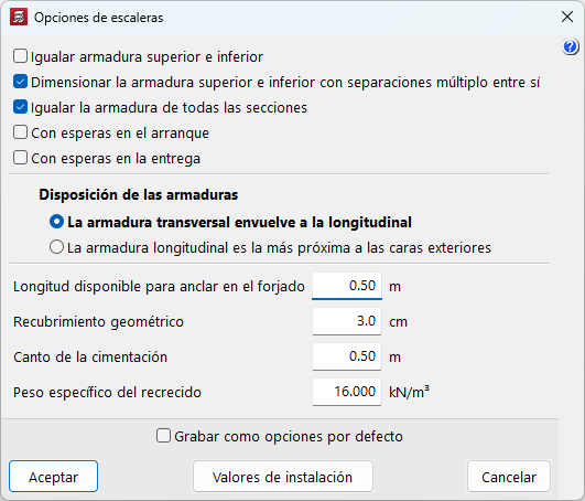
A number of analysis options can be configured to allow users to obtain reinforcements according to their personal preferences. The following is also possible:
- Matching the top and bottom reinforcement.
- Designing the top and bottom reinforcement with multiple spacings between them.
- Matching the reinforcement of all sections.
- Specifying the length available for anchoring in the slab, the geometric overlap of the reinforcement and the depth of the foundation.
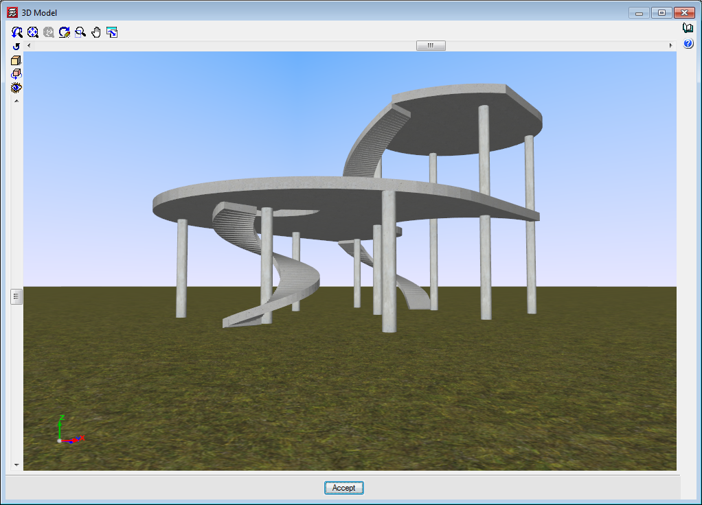
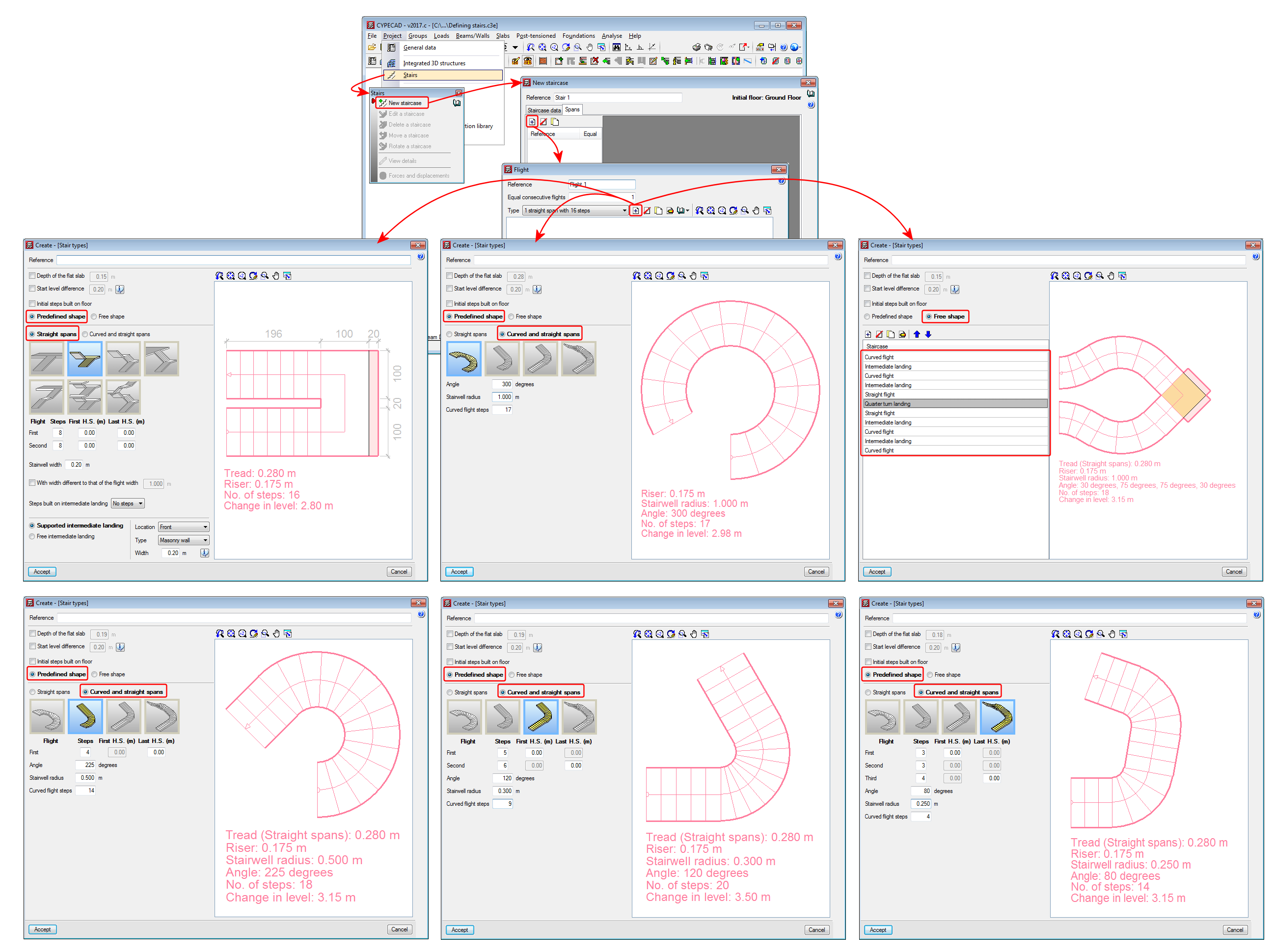
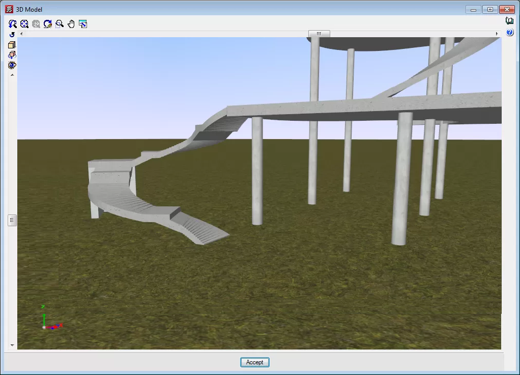
Curved staircases
In the CYPECAD "Stairs" module, users can now enter curved flights of stairs. The "Predefined shapes" of staircases now include the following:
- Only straight span shapes
These are the predefined shapes that were included from previous versions. - Shapes with straight and curved spans
- Curve
- Curve with a straight flight
- Curve with two straight flights
- Two curves with three straight flights
With "Free shape", straight and curved spans can be combined in any desired way. An infinite number of staircase shapes can be defined.

The finite element analysis model for the staircases is, again, separate from the rest of the structure for the analysis. The program automatically transfers the staircase loads to the model of the complete structure at its supports, start, landing and intermediate supports as an averaged linear load.