Project settings
The "Project" section of the main toolbar contains the options for configuring the general project settings:

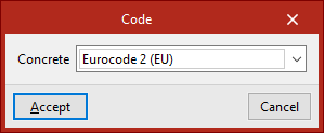
Code
The "Code" option opens a pop-up window where you can select the "Concrete" standard that the program will use in the calculation from those available in the drop-down menu.
| Note: |
|---|
| The codes implemented in CYPE’s programs can be viewed via the following link. |
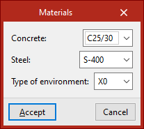
Materials
The "Materials" option opens a pop-up window where you can select the "Concrete" for the beams, the type of "Steel" and the "Type of environment" to be considered from those available in the various drop-down menus, which depend on the selected code.
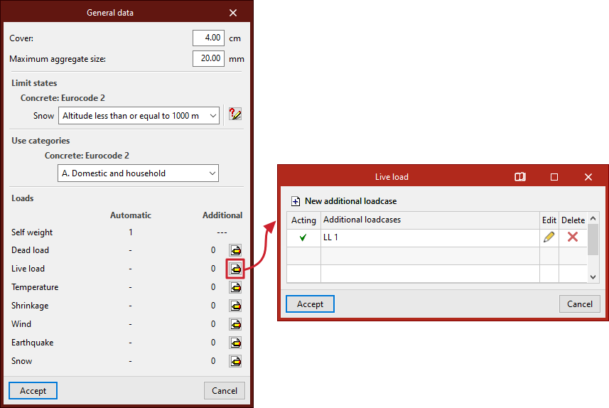
General data
The "General data" option opens a pop-up window describing the following parameters:
- First, enter the "Cover" and "Maximum aggregate size" in the relevant fields.
- Secondly, in the "Limit states" section, the necessary settings are configured for the automatic generation of load combinations for the various project scenarios, which the program performs in accordance with the selected code.
- Thirdly, in the "Use categories" section, select the category of the loads defined in the loadcase from among those specified in the selected code.
- Finally, under "Loads", the loadcases to be considered in the project are defined:
- The "Automatic" column displays the assumptions that the program takes into account automatically, such as the assumption regarding the structure's "dead load".
- In the "Additional" column, you can add further load cases if required. To do this, after clicking the edit button within the desired category, click on "New additional loadcase" and enter a "Reference" and a "Description".
Optionally, the program allows you to tick the "With different load arrangements" box for each of the added loadcases. The concept of load arrangement allows you to define different load states grouped within the same loadcase. Load arrangements can be "Compatible" with one another, "Incompatible" or "Simultaneous".
If several additional loadcases are added, the program displays a “Combinations” table showing the different scenarios and indicating whether they are “Combinable” or “Not combinable”. The “Show combinations” button allows you to list the “Combinations” obtained after manipulating the table.
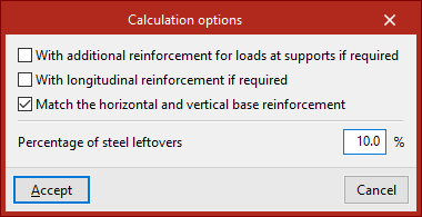
Calculation options
The "Calculation options" that the program allows you to configure are as follows:
- With additional reinforcement for loads at supports if required (optional)
If this option is enabled, reinforcement for support loads will be provided where required by the calculations. If it remains disabled, it will be combined with the basic web reinforcement to create a more uniform reinforcement pattern. - With longitudinal reinforcement if required (optional)
If this option is enabled, top longitudinal reinforcement will be provided where required by the design calculations. If it remains disabled, it will be combined with the base web reinforcement to create a more uniform reinforcement pattern. - Match horizontal and vertical base reinforcement (optional)
If this option is enabled, the horizontal and vertical base reinforcement of the web are aligned. - Percentage of steel leftovers
This option allows you to enter the percentage of wastage or steel loss (between 0 and 15%), which will be applied as increments to the measurements automatically calculated by the program.