Introduction
StruBIM Deep Beams is a software program for analysing, designing and producing reinforcement drawings for deep reinforced concrete beams (wall beams) with a rectangular cross-section.
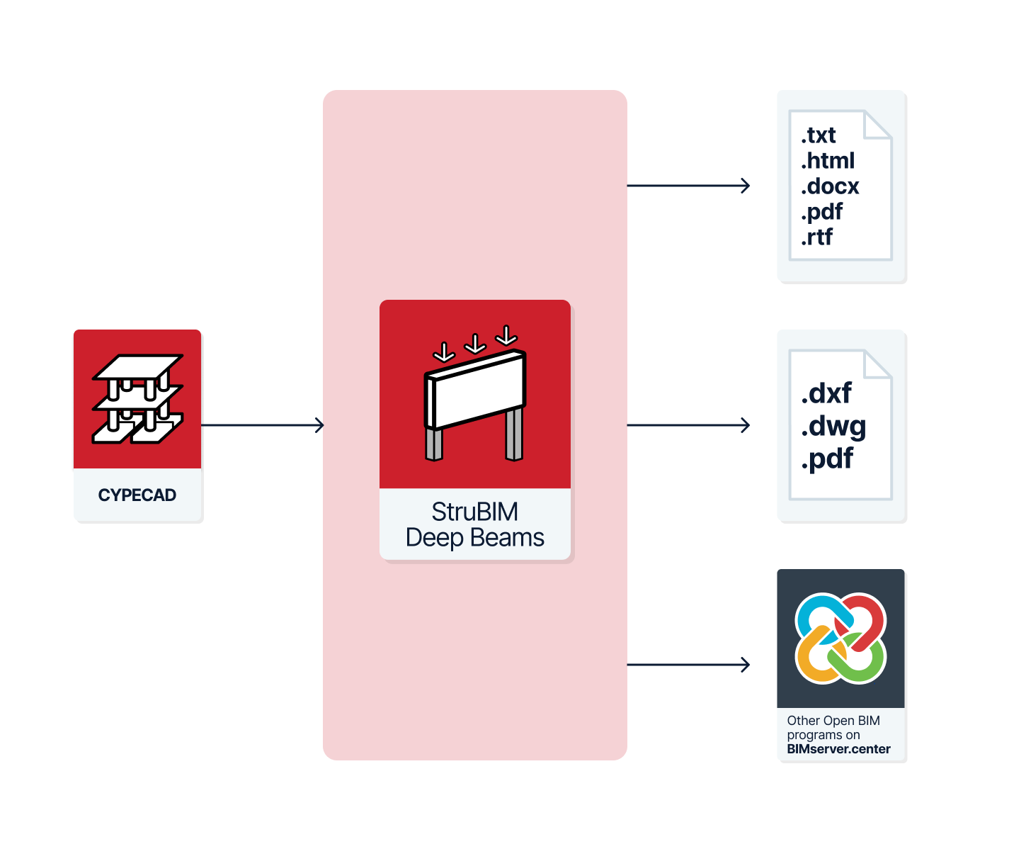
This application is integrated into the Open BIM workflow via the IFC standard:
- Using a wizard, StruBIM Deep Beams imports the geometry of beams from the IFC file that meet the user-specified depth-to-length ratio. The IFC file containing the beams’ geometric information can be generated by other tools linked to the Open BIM project, such as CYPECAD.
- If you import the IFC file again, you can import new beams, modify previously imported beams, or even remove beams that have disappeared from the BIM model.
- StruBIM Deep Beams allows you to export the calculated reinforcement to the BIM model by generating an IFC file. It also generates supporting schedules and drawings of the deep beams, which are exported as attachments to the BIM model.
The app can also be used to enter, define, check and calculate the reinforcement of deep beams independently.
Workflows compatible with the program
As StruBIM Deep Beams is an Open BIM tool and is connected to the BIMserver.center platform, it offers a range of workflow options.
Data entry
Direct entry
- Design and analysis of deep beams by entering their details directly into StruBIM Deep Beams.
Importing BIM models
If you link the StruBIM Deep Beams module to a BIM project on the BIMserver.center platform, you can perform the following actions:
- Importing building structure models containing rectangular concrete beams. This allows deep-flanged beams and their geometry to be generated based on the information extracted from the model. The available options include the following:
- Importing models designed in CYPECAD.
Data output
- Exporting reports to HTML, DOCX, PDF, RTF and TXT formats.
- Exporting drawings to DXF, DWG and PDF formats.
- Exporting data generated using StruBIM Deep Beams to the BIMserver.center platform in IFC and glTF formats. This allows authorised project stakeholders to view the data.
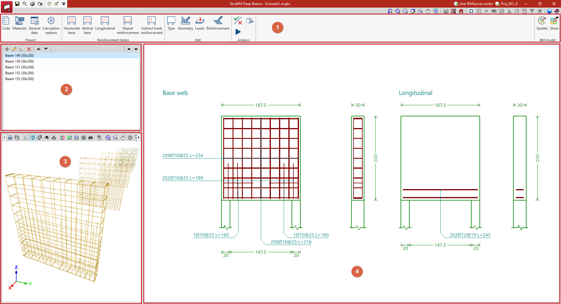
Work environment
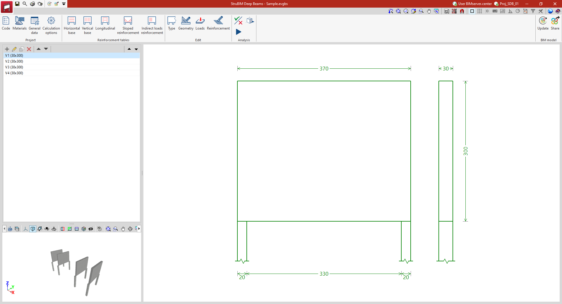
The StruBIM Deep Beams interface features a user-friendly workspace comprising the following areas:
- A top toolbar (1) containing tools for: configuring project parameters; managing reinforcement tables; defining the type and geometry of each deep-flange beam, the loads applied to it, and viewing and editing its reinforcement; checking and designing the beam; and linking the model and exporting the information to a BIMserver.center project.
- On the left-hand side panel, there is a navigator showing the list of deep-flange beams (2) defined in the file and, below that, a 3D view of the imported model (3).
- Finally, the main viewport (4) on the right-hand side of the screen displays the cross-sections and elevations of the selected deep-flange beam, along with the reinforcement layout or design for that beam.
Data input and output sequence for the design and analysis of deep-flange beams
Deep-flanged beams can be defined and analysed in the program using the following sequence of data input and output:
- Creating a new project (from "File", "New").
- (Optional) Linking to BIMserver.center and import of deep-flanged beams based on data extracted from the BIM model.
- Configuring general parameters (options in the "Project" section): selecting codes, definition of materials and/or manual configuration of general data and design options.
- (Optional) Configuring the reinforcement tables (options in the "Assembly tables" group).
- Inserting deep beams (from the beam list on the left-hand side panel, "New") that have not been imported from the BIM model.
- Defining each deep-flanged beam. This is carried out as follows:
- Select the beam from the list in the side panel.
- Define the beam’s "Type", "Geometry" and "Loads" (options in the "Edit" group).
- (Optional) View and/or edit the "Reinforcement" (in the "Edit" section) if you wish to enter and check a reinforcement or examine the reinforcement generated by the program during the design process.
- Analysing, verifying and/or designing deep beams (the "Analysis" module):
- The "Code check" option is used if the beam has been fully defined and you wish to verify the proposed reinforcement.
- The "Design" option is used to allow the program to design the reinforcement of each beam if this has not been defined previously.
- Generating reports (from "File", "Reports").
- Retrieving the beam drawings (from "File", "Drawings").
- (Optional) Exporting to BIMserver.center (under "BIM Model", "Share").
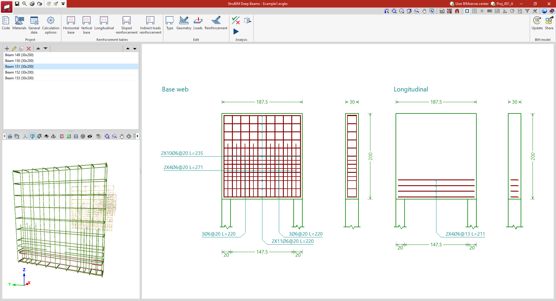
Example
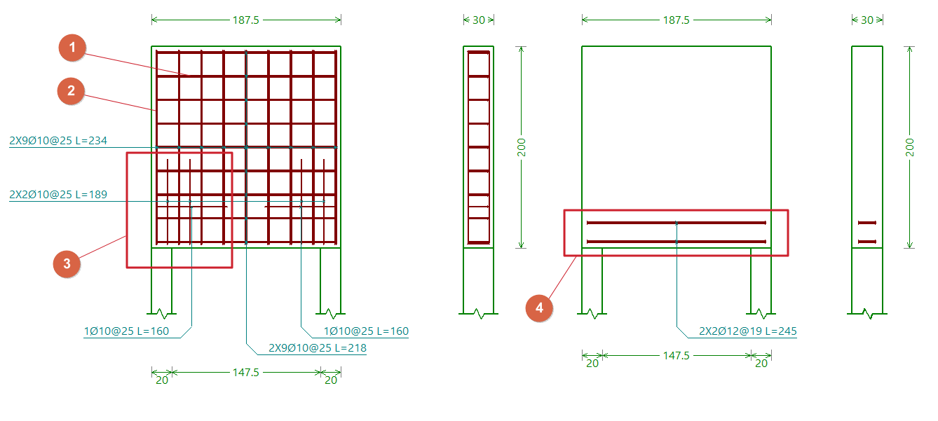
Below is an example of a deep-flange beam that can be analysed using the program, showing the layout of the different reinforcement groups:
- Horizontal base frame of the web.
- Vertical base frame of the web.
- Reinforcement armour for the core.
- Lower longitudinal reinforcement.
Creating a new job, linking to a project and importing data
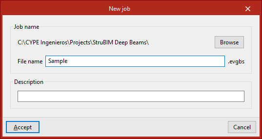
When you launch the app and click on “New”, you are given the option to create a “New job”. After entering the “File name” and “Description”, the project can then be added to an existing project on BIMserver.center.
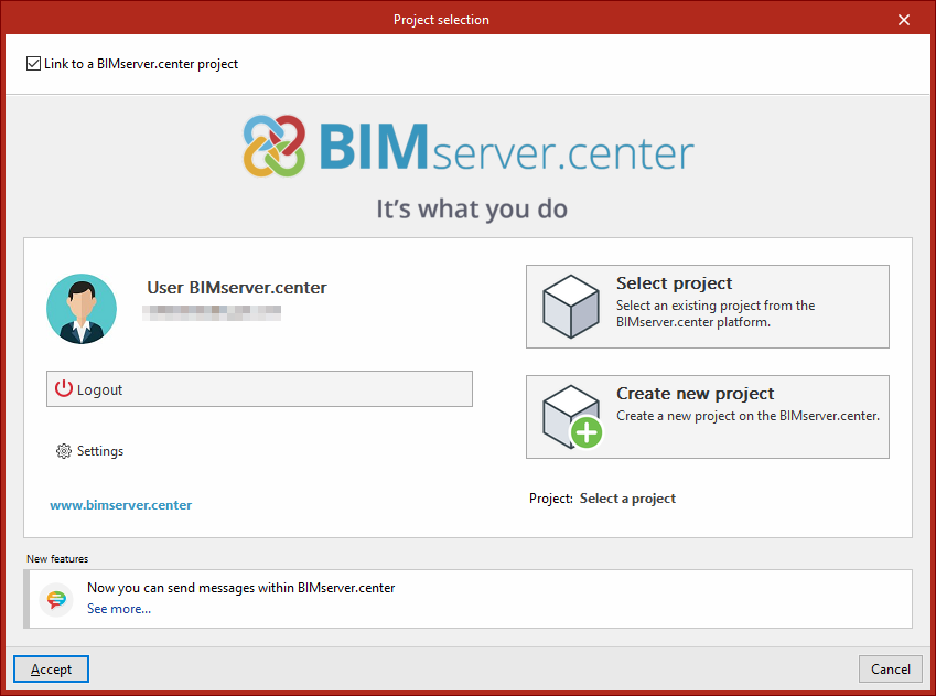
This is done in the "Project selection" window, which offers the following options:
- On the left-hand side, you can log in using a BIMserver.center account.
- On the right, use the "Select project" option to choose an existing project. You also have the option to "Create a new project". In that case, the project you create will be visible on BIMserver.center from that point onwards.
- You have the option to start the project without linking it to the BIMserver.center platform. To do this, simply uncheck the box labelled "Link to a BIMserver.center project", which is located in the top-left corner.
Once the new project has been created, you will be taken to the program’s main interface. At any stage of the project, you can share or import project files via the “BIM Model” panel, located at the top right of the main interface.
Importing BIM models
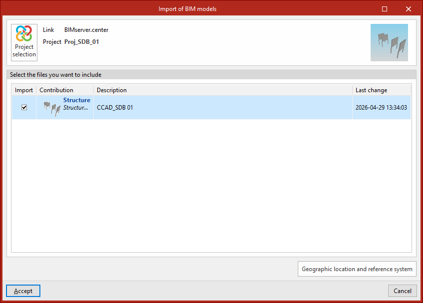
When creating a new project, if you have selected a project hosted on the BIMserver.center platform via "Select project", the "Import BIM models" window will appear, displaying the files contained in that project in IFC format.
The application allows you to include one or more of the existing models in that project. To do this, tick the "Import" box and confirm.
Beam import wizard
The beams extracted from the BIM model can be imported into StruBIM Deep Beams.
To do this, once you have selected the BIM models to import, the program opens a "Beam import" wizard with the following steps:
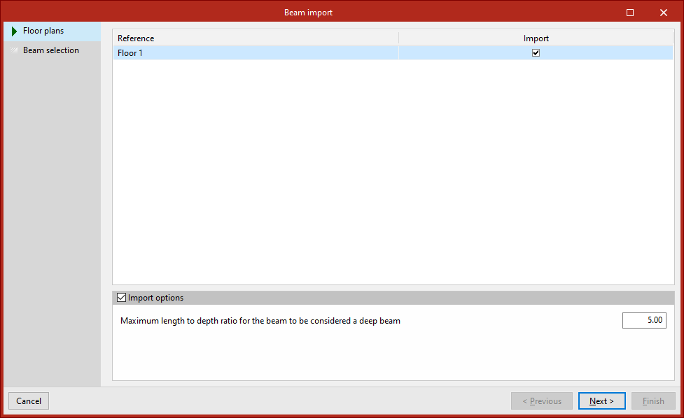
- In the first stage, select the "Floor plans" to be imported. Each one appears in the list with its "Reference" and can be "Imported" by ticking the box in the right-hand column.
By selecting the "Import options" section at the bottom, you must specify the "Maximum length-to-depth ratio for the beam to be considered a deep beam" by entering the value in the corresponding field. Beams with a ratio lower than this value can be imported into the StruBIM Deep Beams model, whilst the remaining ones are ignored.
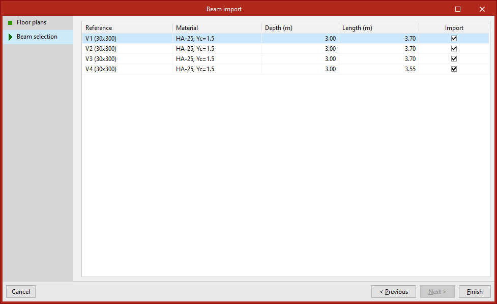
- In the second stage, you need to select the beams you wish to import from the list provided by the program. Each beam is listed with its "Reference", "Material", "Depth" and "Length", and you can "Import" them by ticking the box in the right-hand column.
To complete the import wizard, click "Finish".
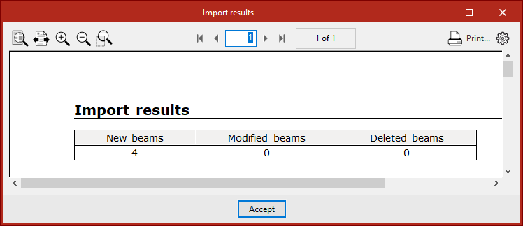
Importing results
Once the import process is complete, the program will display a list of the results, showing the number of new beams generated, modified and/or deleted.
You will then be taken to the program’s main interface. The imported beams will be displayed in the list on the left-hand side panel. From here, you can add further beams if required.
From this point onwards, users can modify the data for any of the imported beams, as well as apply a specific reinforcement scheme and/or carry out their analysis, verification and design.
Project settings
The "Project" section of the main toolbar contains the options for configuring the general project settings:

Code
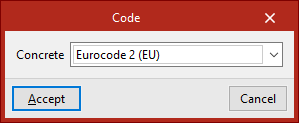
The "Code" option opens a pop-up window where you can select the "Concrete" standard that the program will use in the calculation from those available in the drop-down menu.
| Note: |
|---|
| The codes implemented in CYPE’s programs can be viewed via the following link. |
Materials
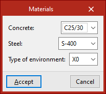
The "Materials" option opens a pop-up window where you can select the "Concrete" for the beams, the type of "Steel" and the "Type of environment" to be considered from those available in the various drop-down menus, which depend on the selected code.
General data
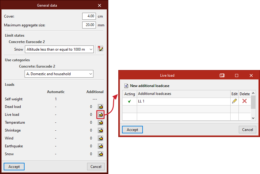
The "General data" option opens a pop-up window describing the following parameters:
- First, enter the "Cover" and "Maximum aggregate size" in the relevant fields.
- Secondly, in the "Limit states" section, the necessary settings are configured for the automatic generation of load combinations for the various project scenarios, which the program performs in accordance with the selected code.
- Thirdly, in the "Use categories" section, select the category of the loads defined in the loadcase from among those specified in the selected code.
- Finally, under "Loads", the loadcases to be considered in the project are defined:
- The "Automatic" column displays the assumptions that the program takes into account automatically, such as the assumption regarding the structure's "dead load".
- In the "Additional" column, you can add further load cases if required. To do this, after clicking the edit button within the desired category, click on "New additional loadcase" and enter a "Reference" and a "Description".
Optionally, the program allows you to tick the "With different load arrangements" box for each of the added loadcases. The concept of load arrangement allows you to define different load states grouped within the same loadcase. Load arrangements can be "Compatible" with one another, "Incompatible" or "Simultaneous".
If several additional loadcases are added, the program displays a “Combinations” table showing the different scenarios and indicating whether they are “Combinable” or “Not combinable”. The “Show combinations” button allows you to list the “Combinations” obtained after manipulating the table.
Calculation options
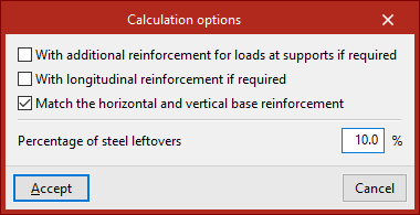
The "Calculation options" that the program allows you to configure are as follows:
- With additional reinforcement for loads at supports if required (optional)
If this option is enabled, reinforcement for support loads will be provided where required by the calculations. If it remains disabled, it will be combined with the basic web reinforcement to create a more uniform reinforcement pattern. - With longitudinal reinforcement if required (optional)
If this option is enabled, top longitudinal reinforcement will be provided where required by the design calculations. If it remains disabled, it will be combined with the base web reinforcement to create a more uniform reinforcement pattern. - Match horizontal and vertical base reinforcement (optional)
If this option is enabled, the horizontal and vertical base reinforcement of the web are aligned. - Percentage of steel leftovers
This option allows you to enter the percentage of wastage or steel loss (between 0 and 15%), which will be applied as increments to the measurements automatically calculated by the program.
Selecting and editing reinforcement tables
The "Reinforcement tables" section of the main toolbar contains the options for managing the reinforcement tables used by the program to design the various groups of reinforcement for deep-flange beams:

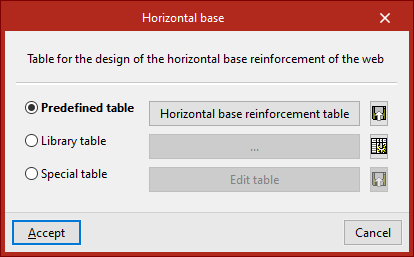
In the pop-up window that appears when you select any of these options, you can use the "Predefined table" provided by the program by default, a "Library table" (if you have previously created any in the library), or a "Special table" defined specifically for the project.
The available options are as follows:
Horizontal base
This reinforcement table is used to determine the dimensions of the horizontal base reinforcement for the web.
Vertical base
This reinforcement table is used to determine the dimensions of the vertical base reinforcement for the web and the suspension reinforcement.
| Note: |
|---|
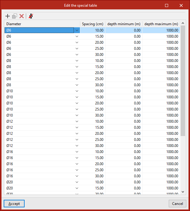
| Each entry in the "Horizontal base" and "Vertical base" reinforcement tables is defined by the "Diameter", "Spacing", "Minimum depth" and "Maximum depth". |
Longitudinal
This reinforcement table is used to determine the dimensions of the lower, central and upper longitudinal reinforcement, and the horizontal reinforcement at the supports.
Sloped reinforcement
This reinforcement table is used to determine the dimensions of the sloped reinforcement at the supports.
Reinforcement of indirect loads
This reinforcement layout table is used to determine the dimensions of the reinforcement for indirect loads.
| Note: |
|---|
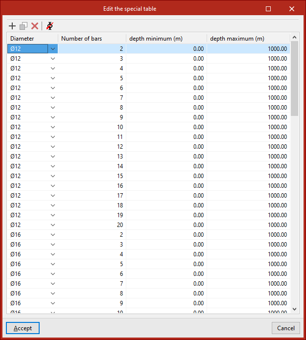
| Each entry in the "Longitudinal", "Sloped reinforcement" and "Indirect loads reinforcement" reinforcement tables is defined by the "Diameter", the "Number of bars", the "Minimum depth" and the "Maximum depth". |
Selecting the beam type and editing the beam geometry
In the "Edit" section of the main toolbar, you will find the options for defining the "Type" and "Geometry" of each deep-flange beam:

Type
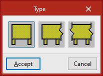
This option allows you to select the type of deep-flange beam from the following:
- Simply supported
The beam is not connected at either end. - Continuous external
The beam continues at one end. - Continuous internal
The beam continues at both ends.
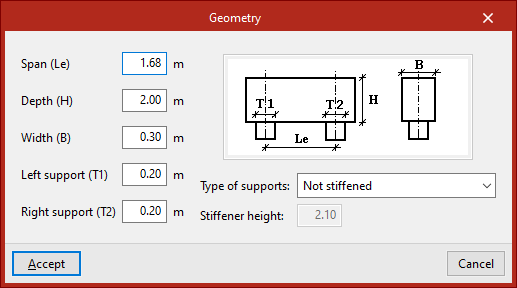
Geometry
This option allows you to define the geometry of the deep-flanged beam selected in the pop-up window.
The following parameters must be specified:
- Span (Le)
- Depth (H)
- Width (B)
- Left support (T1)
- Right support (T2)
These parameters are shown in the diagram on the right.
In addition, the beam’s "Type of supports" must be selected from the drop-down menu. These can be “Not stiffened”, “Stiffened along all its height” or “With stiffener for a given depth”, in which case the "Stiffener height" must be entered.
Defining loads on the beam
In the "Edit" section of the main toolbar, you will find the following option, which allows you to define the loads on each beam:

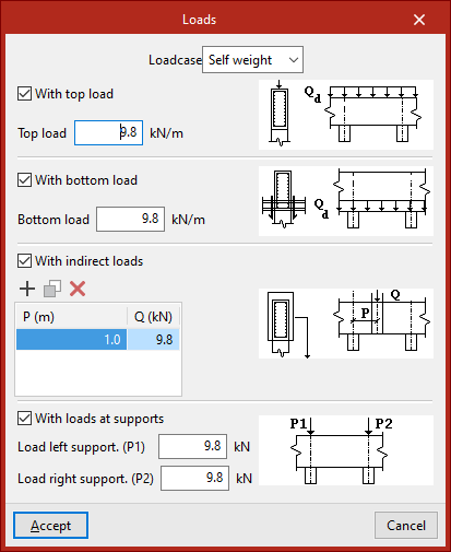
Loads
This option allows you to open a pop-up window in which you can enter the loads applied to each beam.
In the drop-down menu at the top, select the load's "Loadcase" from those previously defined in the project's general settings.
Next, for each loadcase, you can apply loads in different configurations to the beam by selecting the following options:
- With top load (optional)
Enter the value for the beam's "top load". - With bottom load (optional)
Enter the value for the beam's "bottom load". - With indirect loads (optional)
The position is defined and the value of each indirect load on the beam is entered in the list. - With loads at supports (optional)
Enter the load values for the left and right supports ("Load left support(P1)" and "Load right support (P2)")
Viewing and editing the reinforcement
In the "Edit" section of the main toolbar, you will find the following option, which allows you to view and/or modify the reinforcement of each beam:

Reinforcement
Clicking on this option opens a pop-up window where you can view or edit the reinforcement configuration on the beam. This window contains the following tabs, which can be selected or deselected to incorporate different reinforcement groups into the beam:
- Web base reinforcement
- Additional web reinforcement (optional)
- Sloped additional support reinforcement (optional)
- Suspension (optional)
- Indirect loads reinforcement (optional)
- Horizontal reinforcement at supports (optional)
Each of these tabs is described below:
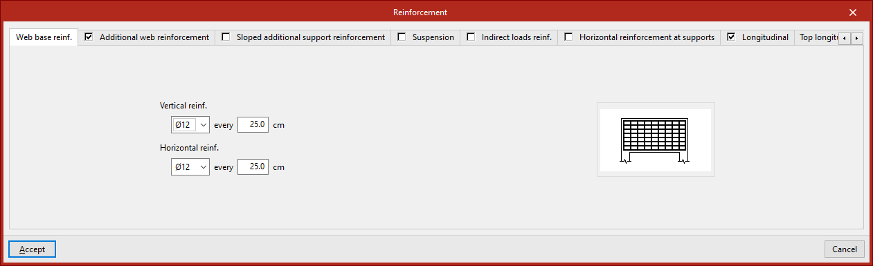
Web base reinforcement
This armour is defined in the "Web base reinforcement" tab. You must specify:
- The diameter and spacing of the bars in the "Vertical reinforcement",
- The diameter and spacing of the bars in the "Horizontal reinforcement".
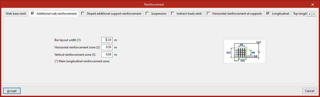
Additional web reinforcement
This armour is defined in the "Additional web reinforcement" tab. You must specify:
- The "Bar layout width",
- The "Horizontal reinforcement zone",
- The "Vertical reinforcement zone".
The diagram on this tab illustrates the above parameters for clarity, as well as the "Main longitudinal reinforcement zone".
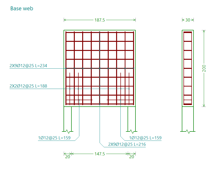
The base web and the web base reinforcement are shown together in the "Base web" assembly drawing.
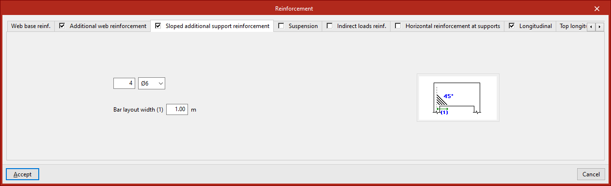
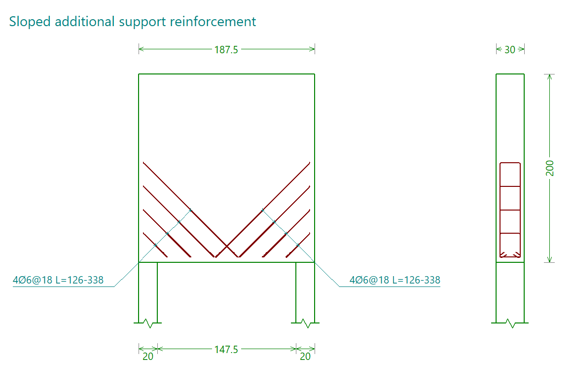
Sloped additional reinforcement at support
This reinforcement is defined in the "Sloped additional support reinforcement" tab. You must specify:
- The number of bars and the diameter,
- The "Bar layout width".
The diagram in this tab illustrates this final parameter to aid understanding, as well as showing the angle at which the bars are positioned (45°).
The inclined reinforcement at the supports is shown in the reinforcement diagram labelled "Sloped additional support reinforcement".
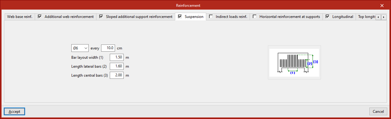
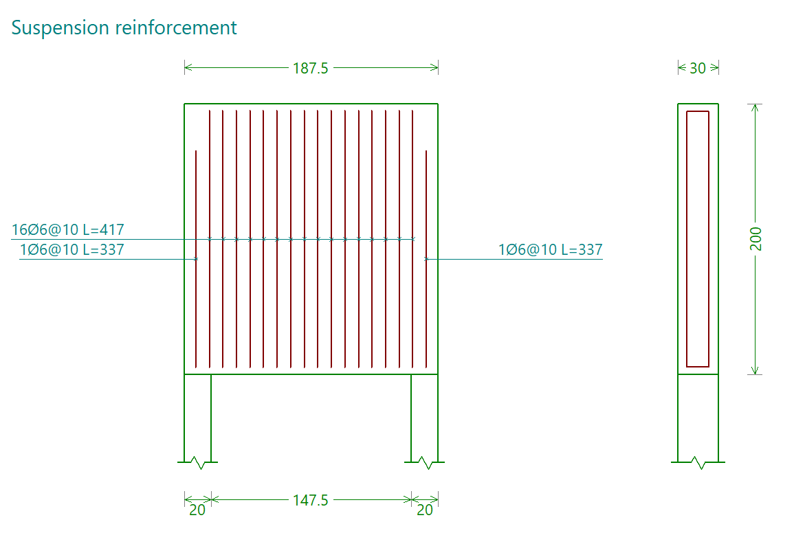
Suspension reinforcement
This reinforcement is defined in the "Suspension" tab. You must specify:
- The diameter of the bars and the spacing between them
- The "Bar layout width"
- The length of the lateral and central bars ("Length lateral bars", "Length central bars")
These parameters are illustrated in the diagram on this tab to make them easier to understand.
The suspension frame is shown in the reinforcement diagram labelled "Suspension frame".
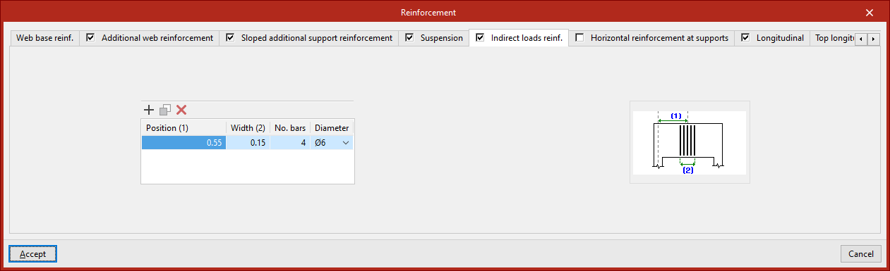
Indirect loads reinforcement
This reinforcement is defined in the "Indirect load references" tab, which displays a list where you can "Add", "Copy" or "Delete" different reinforcement groups.
For each of them, you must specify:
- The "Position" of the centre of the group relative to the axis of a support at the end of the beam;
- The "Width" of the group
- The "Number of bars"
- The "diameter" of the bars in the pack
These parameters are illustrated in the diagram on this tab to make them easier to understand.
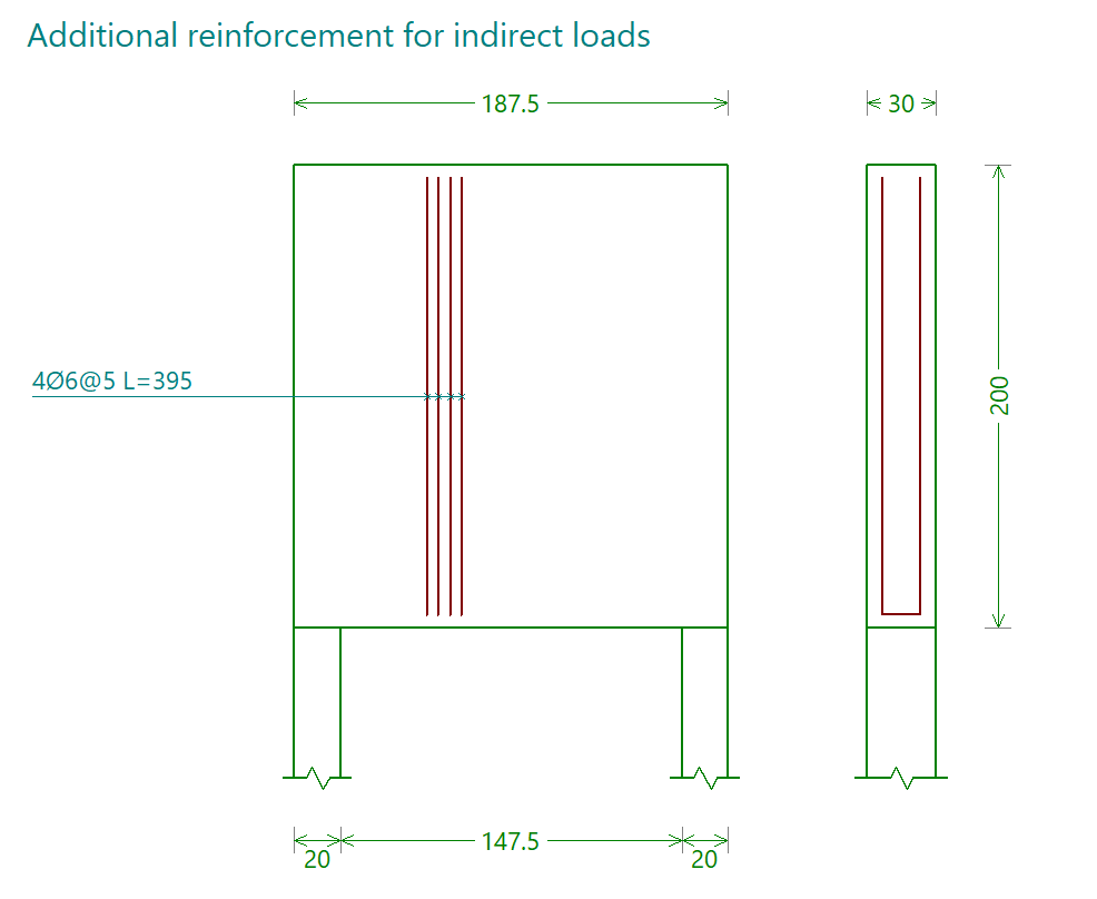
The reinforcement for indirect loads is shown in the reinforcement diagram labelled "Additional reinforcement for indirect loads".
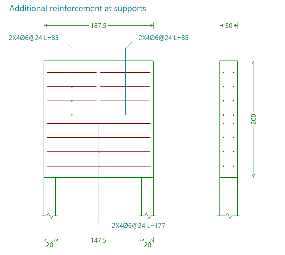
Horizontal reinforcement at the supports
This reinforcement is defined in the "Horizontal reinforcement at supports" tab. It is organised as follows:
Upper armour
The horizontal reinforcement "Top reinforcement" at the supports is defined by entering the following for both the "Left support" and the "Right support":
- the number and diameter of the bars,
- and the "Bar length".
You must specify the "Distance" of this assembly from the top face of the beam, as well as the "Bar spacing".
Lower armour
The horizontal reinforcement "bottom reinforcement" is defined by specifying the number and diameter of the bars, the "distance" of this reinforcement from the underside of the beam, and the "bar spacing".
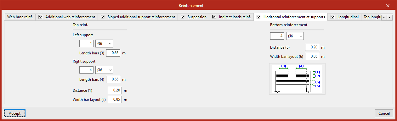
The horizontal reinforcement at the supports is shown in the reinforcement plan labelled "Reinforcement at supports".
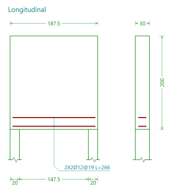
Lower longitudinal frame
This reinforcement is defined in the "Longitudinal" tab. You must specify:
- the number of bars and their diameter,
- and the "Bar spacing".
These parameters are illustrated in the diagram on this tab to make them easier to understand.
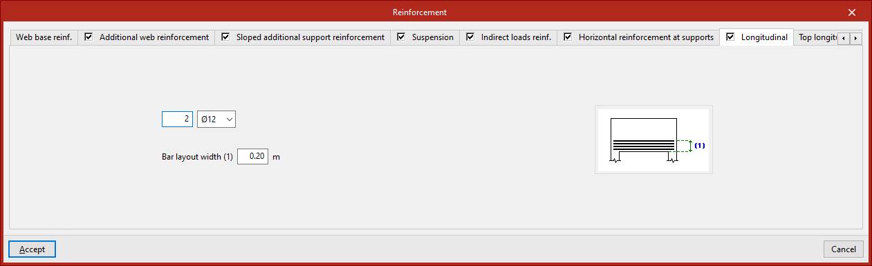
The lower longitudinal reinforcement is shown in the reinforcement drawing labelled "Longitudinal".
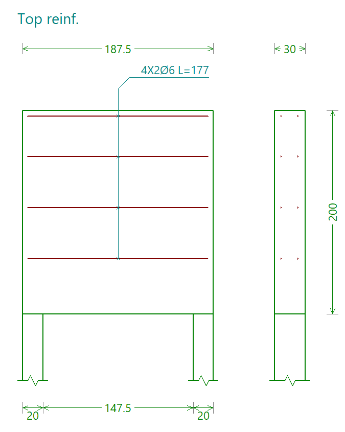
Top and central longitudinal reinforcement
These reinforcements are defined in the "Top longitudinal" tab.
If "With top reinforcement" is selected, you must specify the number of bars and their diameter.
If "With central longitudinal reinforcement" is selected, the following is indicated:
- The number of bars and their diameter
- The "Width" across which the bars are arranged
For both reinforcements, their length is specified ("Length of horizontal bars"). The "Width" of the top longitudinal reinforcement is also specified.
These parameters are illustrated in the diagram on this tab to make them easier to understand.

The top and central longitudinal reinforcements are shown in the assembly diagram labelled "Top framework".
Analysis, checks and design
The "Edit" section of the main toolbar contains options for calculating, checking and/or dimensioning deep beams, as well as for displaying a 3D view of the model:

Viewing the checks
This option performs the design checks on the selected beam using the data defined in the model. It does not dimension the reinforcement.
Designing
This option performs a full structural analysis of the selected beam, carrying out the required checks and determining the reinforcement.
| Note: |
|---|
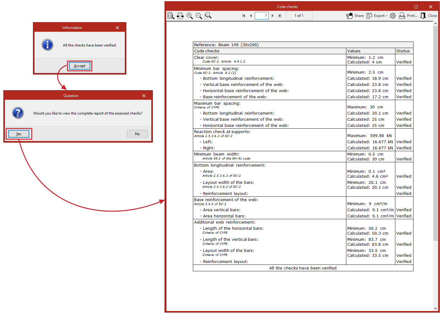
| When you use the "Consult checks" or "Dimension" options, the program will display an "Information" window indicating whether or not all the checks have been met. Once you confirm, you can view on screen the full report of checks carried out on the beam, which can be printed and exported in various formats. |
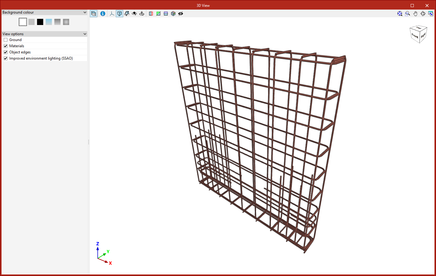
3D view
This option opens a window displaying a detailed three-dimensional view of the reinforcement created in the selected beam.
Results output
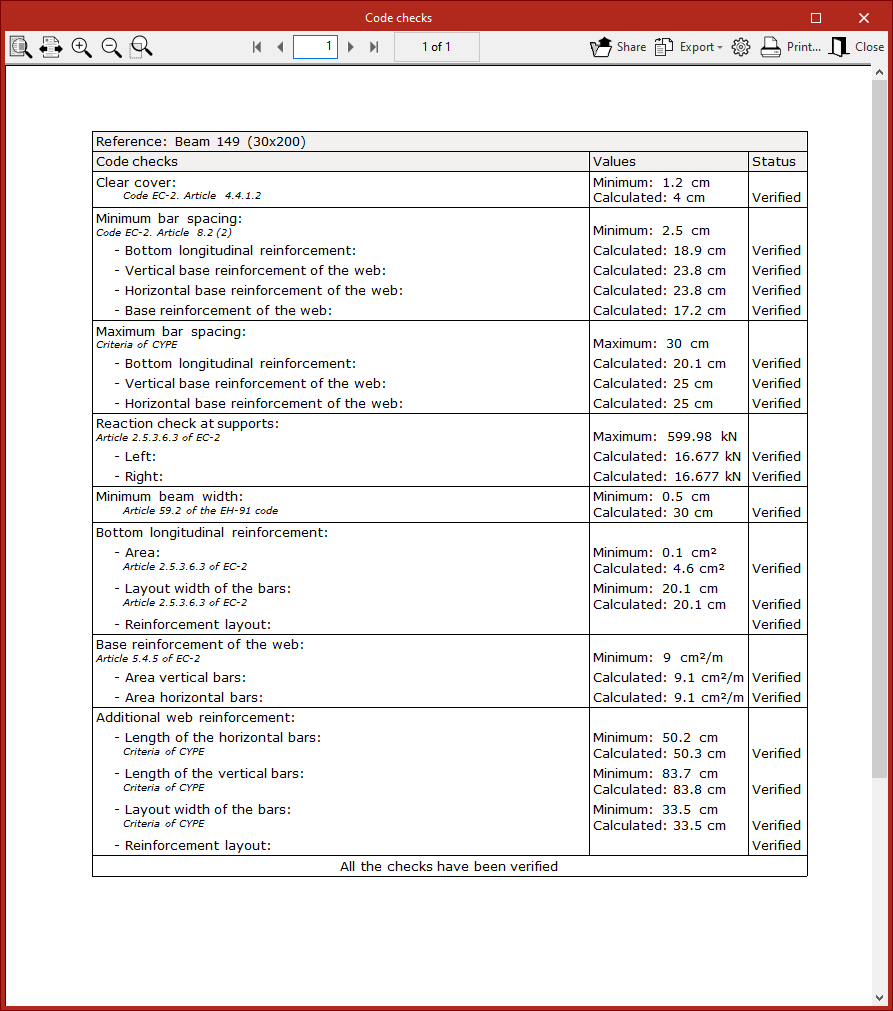
Code checks
When calculating each beam using the "Consult checks" or "Design" options, the program displays a specific report of the checks carried out on that beam.
This report can be printed directly or exported to HTML, PDF, TXT, RTF or DOCX files.
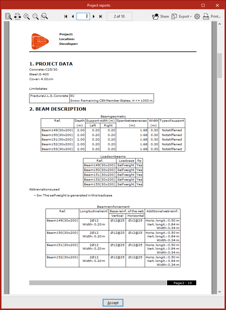
Job report
The program allows you to print the complete job report directly or generate HTML, PDF, TXT, RTF or DOCX files.
This report can be accessed via the "Reports" option in the "File" menu or from the toolbar at the top left.
The list of structural elements includes details of the beams that have been calculated and comprises the following sections:
- Project data
- Beam description
- Detailed quantities
- Verification
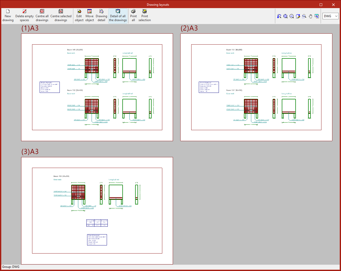
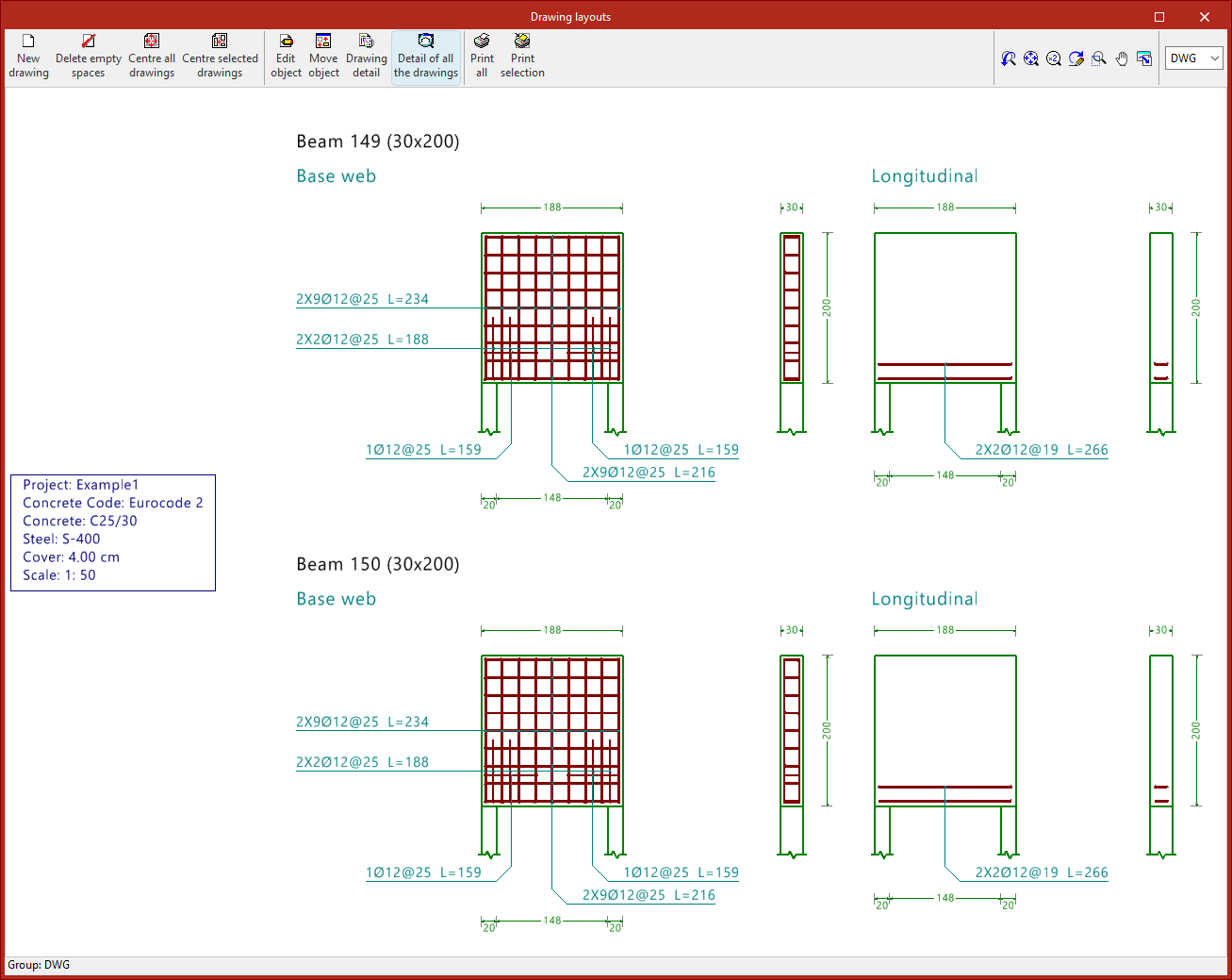
Drawings in DWG, DXF or PDF format
The program allows you to print the project drawings on any printer set up on your computer, or to create DWG, DXF or PDF files.
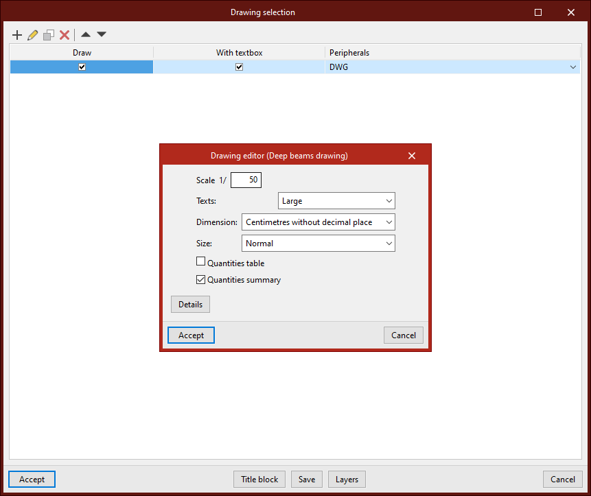
The drawing editor allows you to configure the following options:
- Scale
- Texts
- Dimension
- Size
- Quantities table (optional)
- Quantities summary (optional)
- Details
You can access the drawings via the "Drawings" option in the "File" menu or from the toolbar at the top left.
IFC and BVBS files
When exporting the project to the BIMserver.center platform, files are exported in IFC format containing information on the calculated reinforcement. In addition, it is possible to generate one or more BVBS files containing information on the rebar detailing.
GLTF file compatible with BIMserver.center
When exporting the project to the BIMserver.center platform, a 3D model in GLTF format is also exported for integration into the Open BIM project, enabling the reinforcement to be visualised:
- On the online platform
- In the BIMserver.center app for iOS and Android
- In virtual reality and augmented reality
- In other CYPE programs
Options available in StruBIM Deep Beams
The "BIM model" section of the main toolbar contains the features required to use the program alongside other BIMserver.center tools.

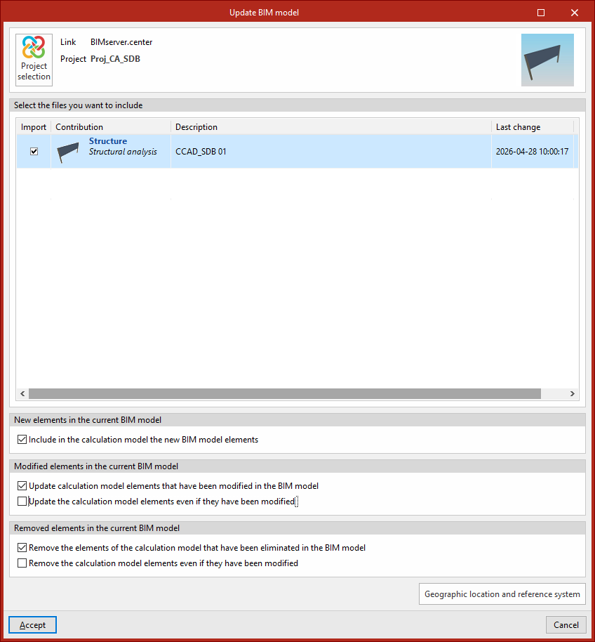
Updating
Update the information contained in the models previously imported into the project, or import new models if required.
In addition, in this window, the program offers the following options, which allow you to add new beams to the model, modify them or delete them, based on the updated information in the BIM model:
- New elements in the current BIM model
In this section, you can "Include the new elements from the BIM model in the calculation model" if this option is enabled. - Elements modified in the current BIM model
In this section, you can "Update the elements of the calculation model that have been modified in the BIM model" if this option is enabled.
If this option is enabled, you can choose whether to "Update the elements of the calculation model even if they have been modified" or not, by checking or unchecking this box. - Elements removed from the current BIM model
In this section, you can "Remove elements from the calculation model that have been deleted from the BIM model" if this option is enabled.
If this option is enabled, you can choose whether to "Remove elements from the calculation model even if they have been modified" by checking or unchecking this box.
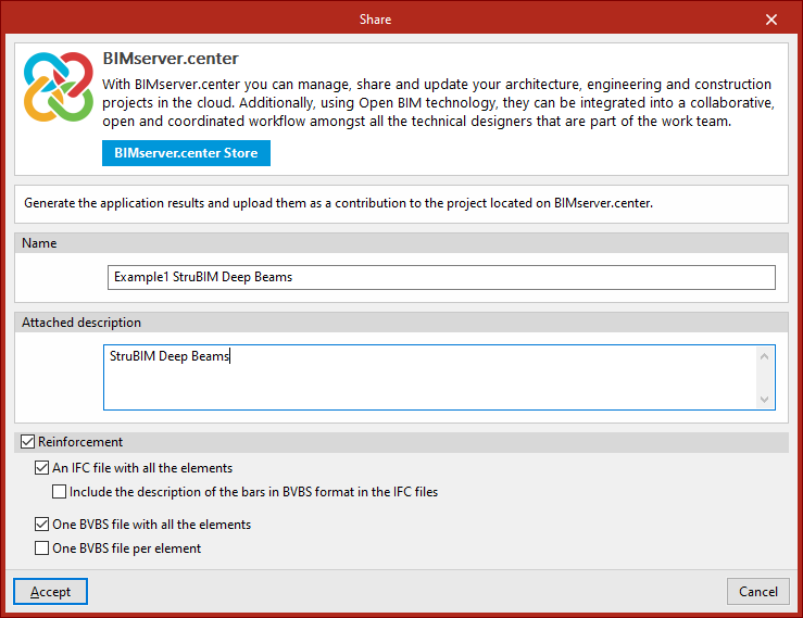
Sharing
Export the installation data generated by the program to BIMserver.center so that you can share it with other users.
During the export process, you can specify the details of the .ifc file to be exported and select any additional files you wish to share:
- Name
- Attached description
- Reinforcement (optional)
If this option is enabled, files in IFC and/or BVBS format can be generated containing information on the model’s reinforcement. The following options can be configured:- An IFC file with all elements
Generates a single .ifc file that includes the reinforcement for the entire model. - Includethe description of the bars in BVBS format in IFC
files
In .ifc files, an additional parameter is added to each bar containing its description in BVBS format, which provides the necessary information on the shape of each bar for manufacturing purposes. - A BVBS file with all the elements
Generates a single .bvbs file that includes all the reinforcement bars in the project. - One BVBS file per element
Generates a separate .bvbs file for each element in the project.
- An IFC file with all elements