Viewing and editing the reinforcement
In the "Edit" section of the main toolbar, you will find the following option, which allows you to view and/or modify the reinforcement of each beam:

Reinforcement
Clicking on this option opens a pop-up window where you can view or edit the reinforcement configuration on the beam. This window contains the following tabs, which can be selected or deselected to incorporate different reinforcement groups into the beam:
- Web base reinforcement
- Additional web reinforcement (optional)
- Sloped additional support reinforcement (optional)
- Suspension (optional)
- Indirect loads reinforcement (optional)
- Horizontal reinforcement at supports (optional)
Each of these tabs is described below:
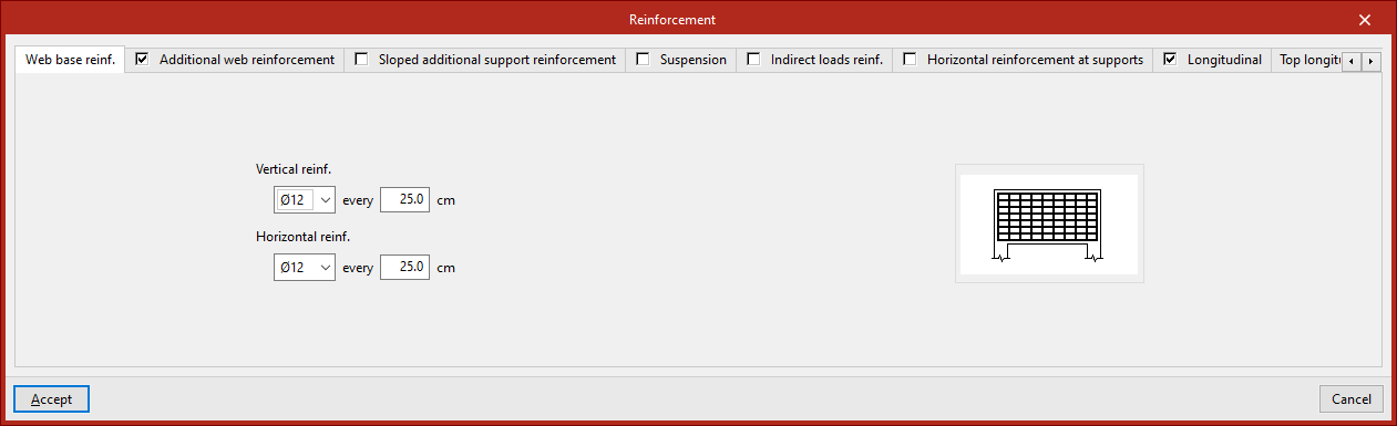
Web base reinforcement
This armour is defined in the "Web base reinforcement" tab. You must specify:
- The diameter and spacing of the bars in the "Vertical reinforcement",
- The diameter and spacing of the bars in the "Horizontal reinforcement".
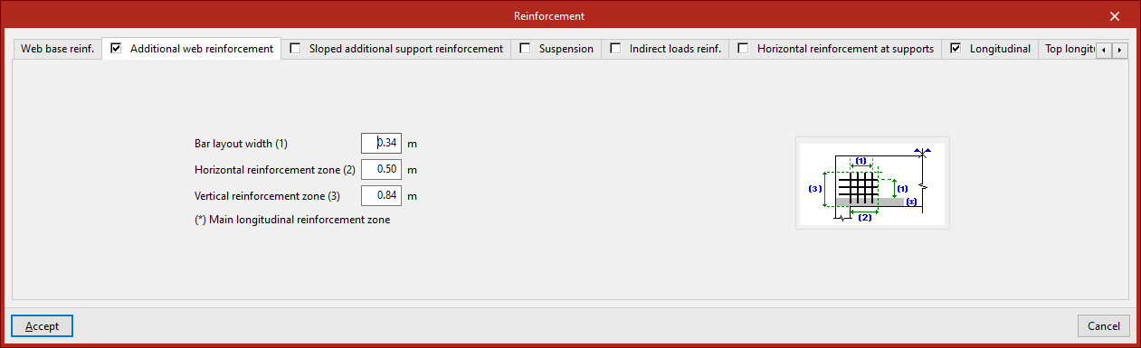
Additional web reinforcement
This armour is defined in the "Additional web reinforcement" tab. You must specify:
- The "Bar layout width",
- The "Horizontal reinforcement zone",
- The "Vertical reinforcement zone".
The diagram on this tab illustrates the above parameters for clarity, as well as the "Main longitudinal reinforcement zone".
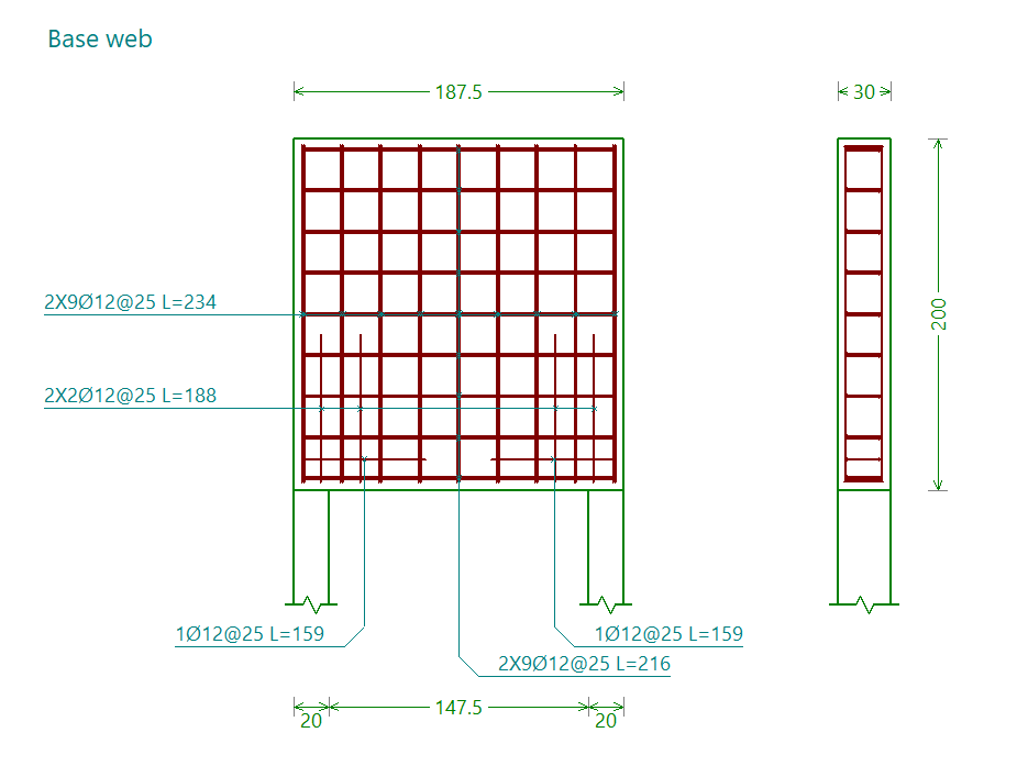
The base web and the web base reinforcement are shown together in the "Base web" assembly drawing.
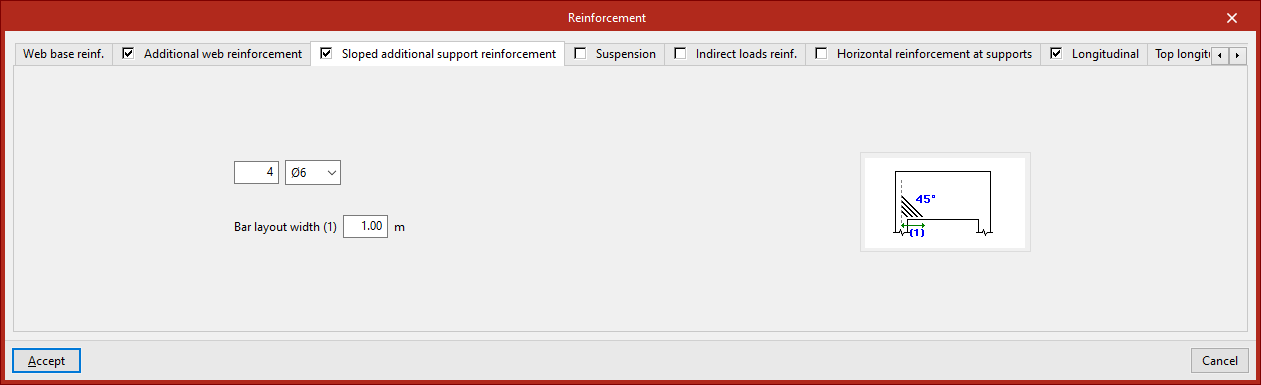
Sloped additional reinforcement at support
This reinforcement is defined in the "Sloped additional support reinforcement" tab. You must specify:
- The number of bars and the diameter,
- The "Bar layout width".
The diagram in this tab illustrates this final parameter to aid understanding, as well as showing the angle at which the bars are positioned (45°).
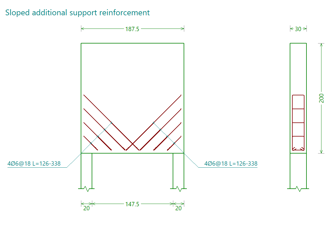
The inclined reinforcement at the supports is shown in the reinforcement diagram labelled "Sloped additional support reinforcement".
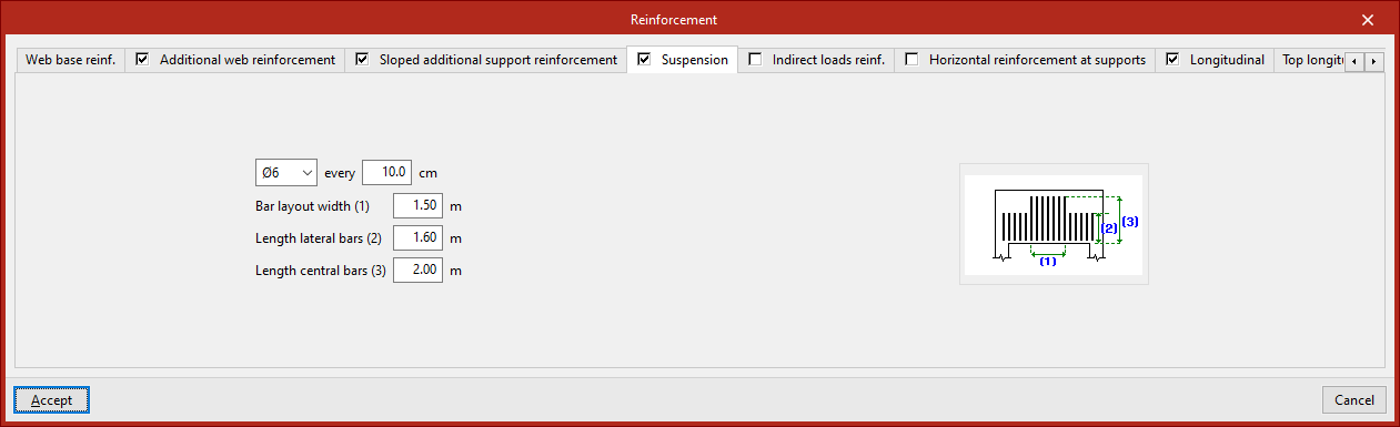
Suspension reinforcement
This reinforcement is defined in the "Suspension" tab. You must specify:
- The diameter of the bars and the spacing between them
- The "Bar layout width"
- The length of the lateral and central bars ("Length lateral bars", "Length central bars")
These parameters are illustrated in the diagram on this tab to make them easier to understand.
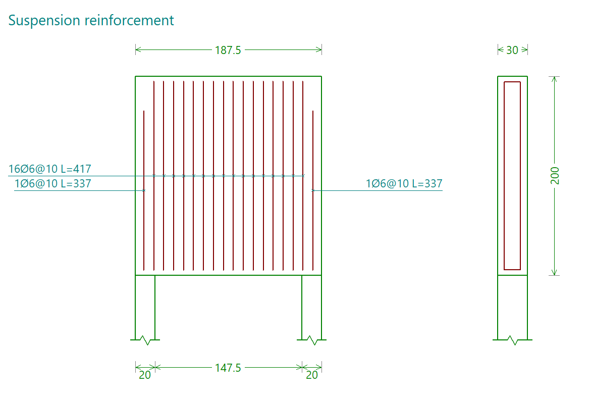
The suspension frame is shown in the reinforcement diagram labelled "Suspension frame".
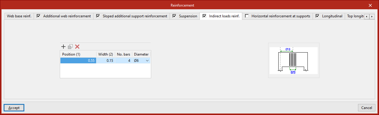
Indirect loads reinforcement
This reinforcement is defined in the "Indirect load references" tab, which displays a list where you can "Add", "Copy" or "Delete" different reinforcement groups.
For each of them, you must specify:
- The "Position" of the centre of the group relative to the axis of a support at the end of the beam;
- The "Width" of the group
- The "Number of bars"
- The "diameter" of the bars in the pack
These parameters are illustrated in the diagram on this tab to make them easier to understand.
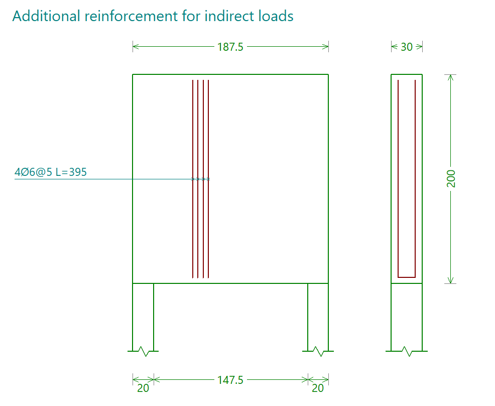
The reinforcement for indirect loads is shown in the reinforcement diagram labelled "Additional reinforcement for indirect loads".
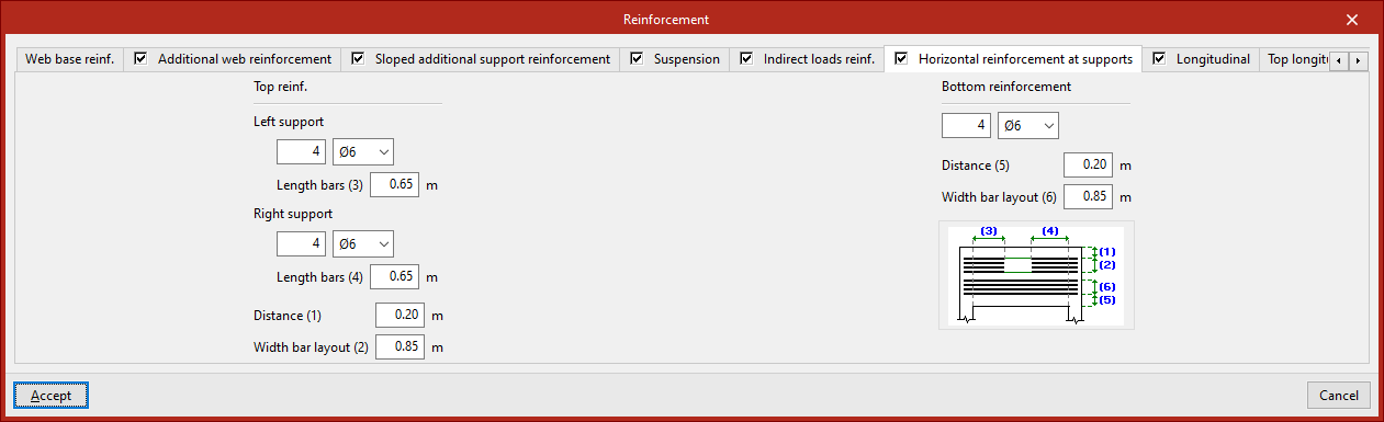
Horizontal reinforcement at the supports
This reinforcement is defined in the "Horizontal reinforcement at supports" tab. It is organised as follows:
Upper armour
The horizontal reinforcement "Top reinforcement" at the supports is defined by entering the following for both the "Left support" and the "Right support":
- the number and diameter of the bars,
- and the "Bar length".
You must specify the "Distance" of this assembly from the top face of the beam, as well as the "Bar spacing".
Lower armour
The horizontal reinforcement "bottom reinforcement" is defined by specifying the number and diameter of the bars, the "distance" of this reinforcement from the underside of the beam, and the "bar spacing".
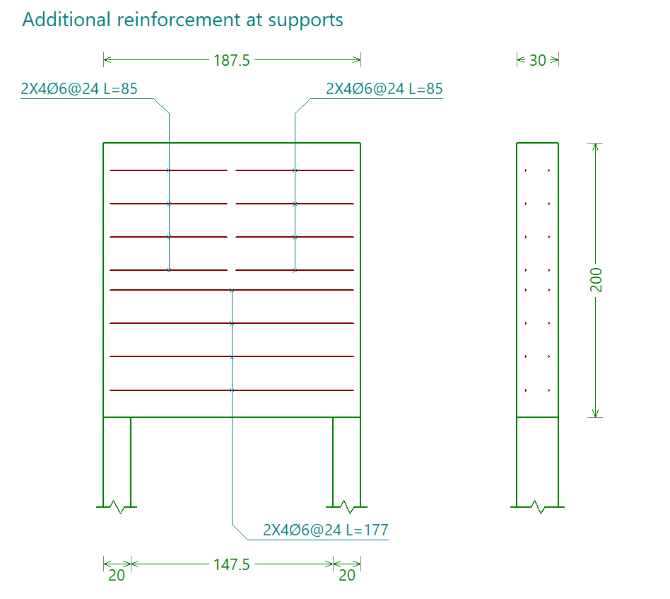
The horizontal reinforcement at the supports is shown in the reinforcement plan labelled "Reinforcement at supports".
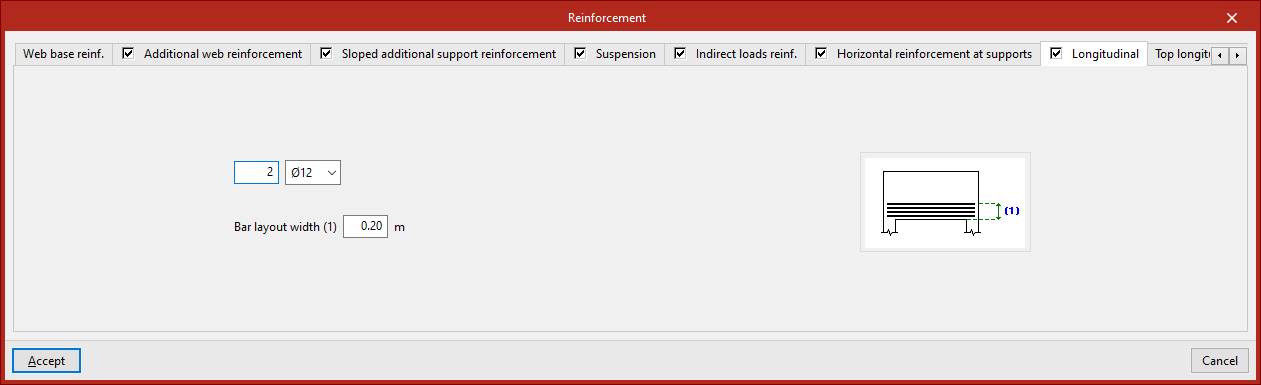
Lower longitudinal frame
This reinforcement is defined in the "Longitudinal" tab. You must specify:
- the number of bars and their diameter,
- and the "Bar spacing".
These parameters are illustrated in the diagram on this tab to make them easier to understand.
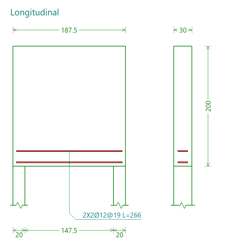
The lower longitudinal reinforcement is shown in the reinforcement drawing labelled "Longitudinal".
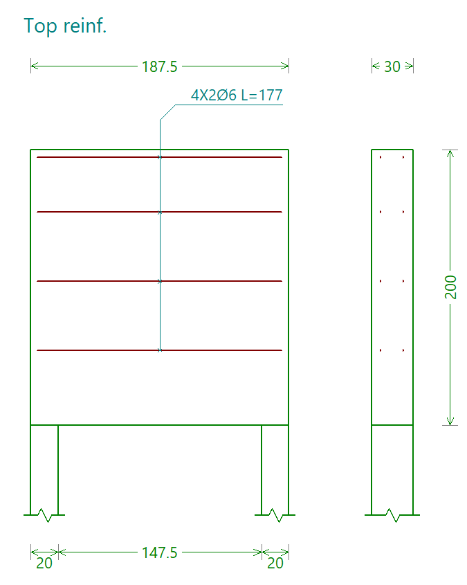
Top and central longitudinal reinforcement
These reinforcements are defined in the "Top longitudinal" tab.
If "With top reinforcement" is selected, you must specify the number of bars and their diameter.
If "With central longitudinal reinforcement" is selected, the following is indicated:
- The number of bars and their diameter
- The "Width" across which the bars are arranged
For both reinforcements, their length is specified ("Length of horizontal bars"). The "Width" of the top longitudinal reinforcement is also specified.
These parameters are illustrated in the diagram on this tab to make them easier to understand.

The top and central longitudinal reinforcements are shown in the assembly diagram labelled "Top framework".