3D view of load-bearing sections and reinforcement in shear walls
In the "3D view" section of the main toolbar on the "Shear walls" tab, you will find options that allow you to view the following information about the project elements:

Resistant sections
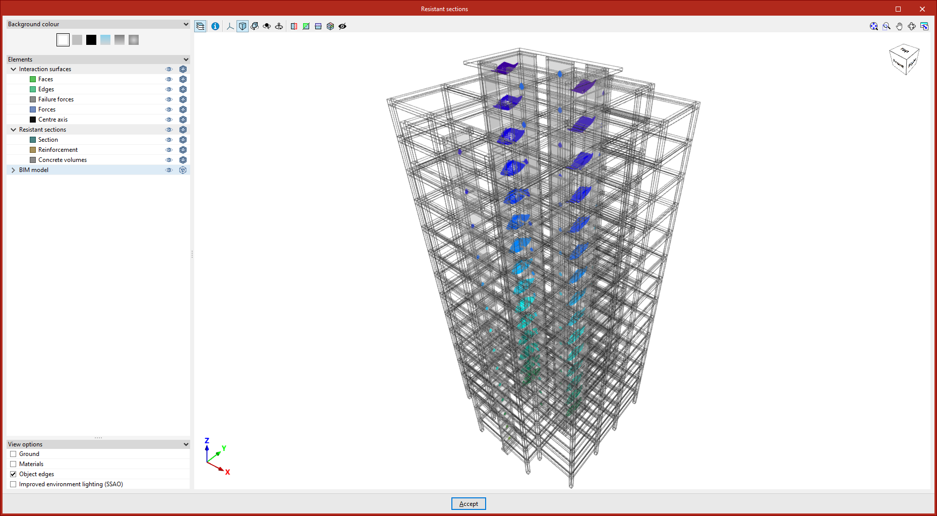
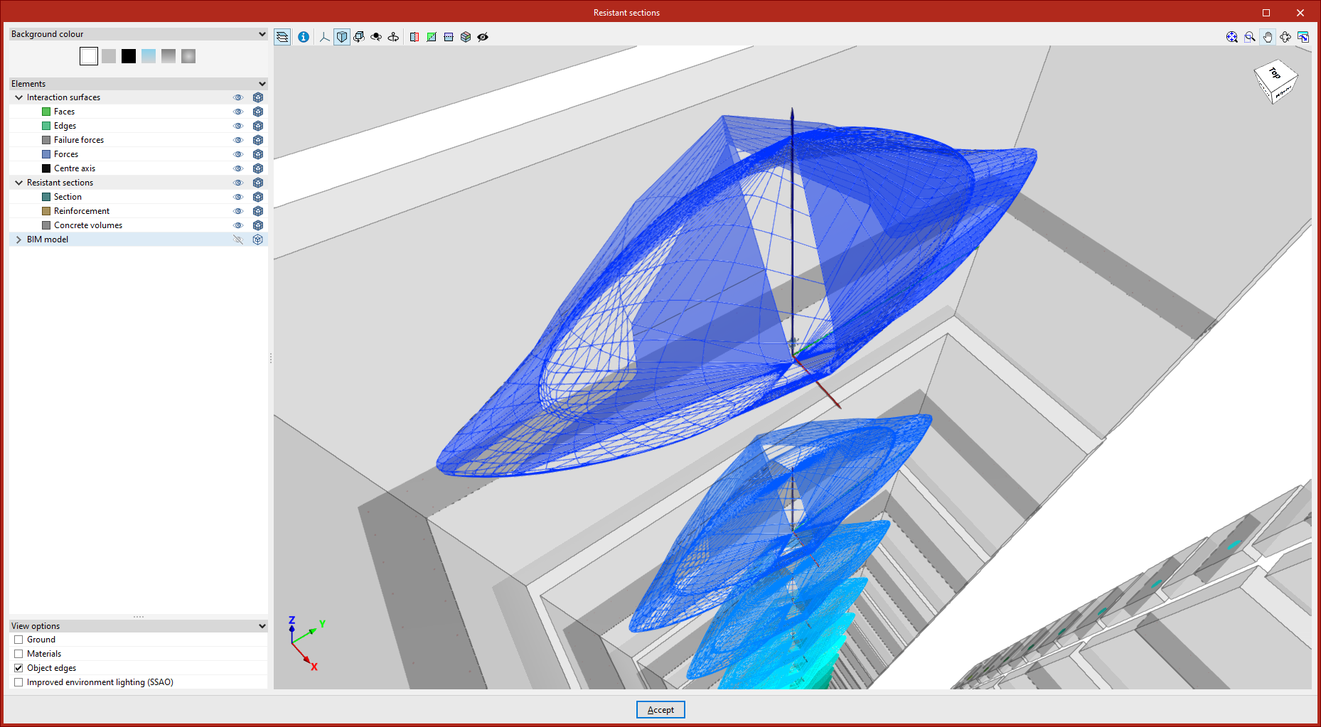
This option opens a window that allows you to view the interaction diagrams and the load-bearing sections of shear walls in a three-dimensional environment.
In the left-hand side panel, you can enable the display of the following information:
- Interaction surfaces
Interaction surfaces are 3D visualisation tools that use curves in space to represent the load-bearing capacity of wall sections under different load combinations.- Faces
Displays the faces that make up the interaction surface on each wall section. - Edges
Displays the edges that form the interaction surface on each wall section. - Failure forces
Places the points on the interaction surface corresponding to the stress concentrations in the cross-section for each section of the wall. - Acting forces
Places the points corresponding to the applied forces on the diagram for each section of the wall. - Axes
Displays the axes of the interaction surface corresponding to the axial force and the moments in both directions.
- Faces
- Resistance sections
The program also displays the following information about the project’s shear walls in this view:- Section
Displays a two-dimensional representation of the cross-section of each section of the retaining walls. - Reinforcement
Displays a two-dimensional representation of the reinforcement cross-section for each bay of the shear walls. - Concrete volumes
Displays a three-dimensional representation of the concrete volumes of the shear walls.
- Section
- BIM Model
Enables the display of the models included in the project.
Reinforcement
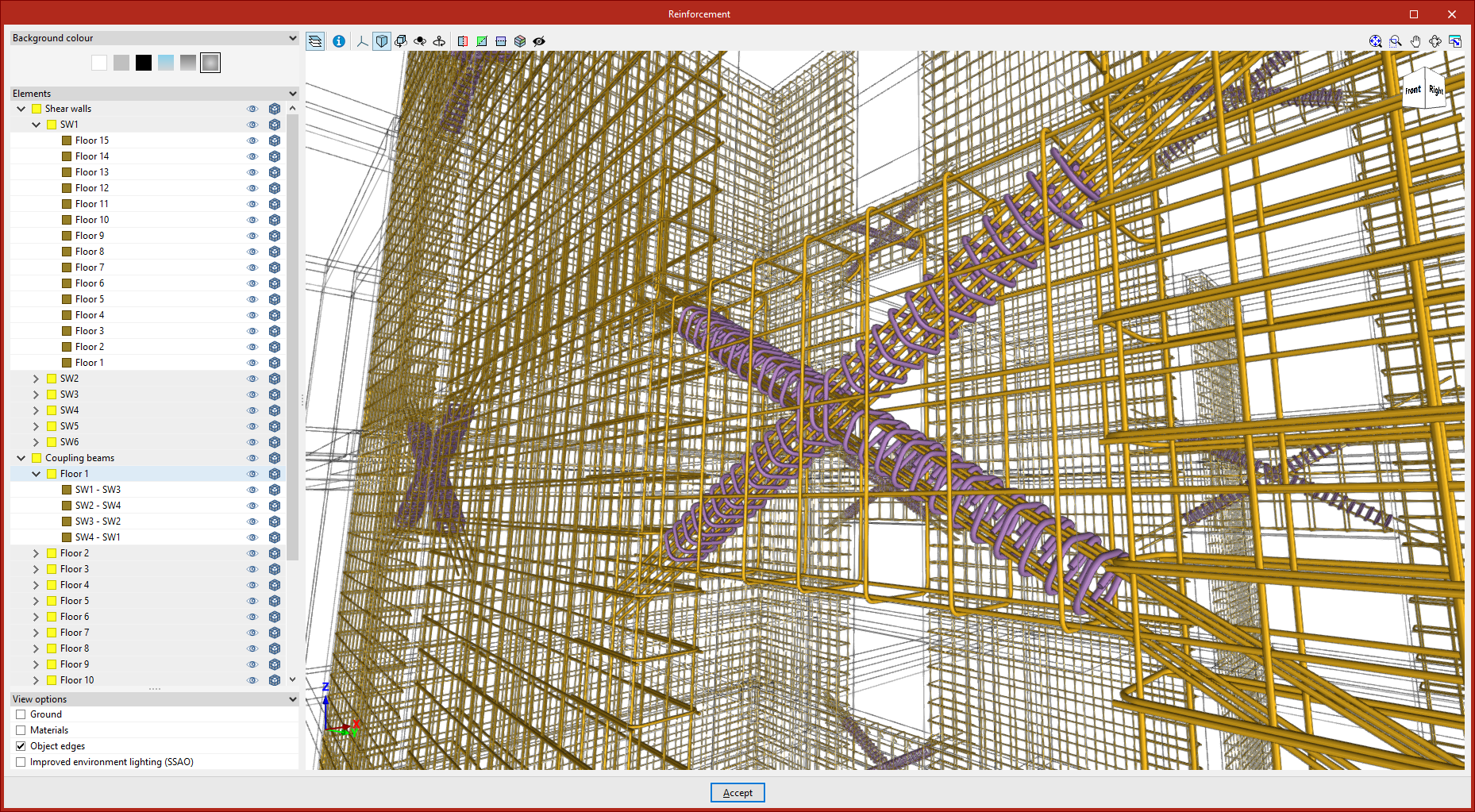
This option opens a window that displays a three-dimensional representation of the reinforcement for the project’s structural elements, including both “Shear walls” and “Connecting beams”.
In the side panel, you can enable or disable the display of elements of each type, for each wall or section of wall, and for each beam or group of beams.
In addition, the "BIM Model" option can be used to display the models included in the project.