Introduction
StruBIM Shear Walls is a program for designing reinforced concrete shear walls and tie beams.
This app is integrated into the Open BIM workflow. As such, StruBIM Shear Walls can import the shear walls and tie beams, along with the analysis results, from the Open BIM project to which it is connected.
With this data, users can design, edit and check the reinforcement for the various sections of shear walls and tie beams in accordance with the applicable standards.
Once the reinforcement design process is complete, the results can be generated and exported. The program offers reinforcement reports and verification reports (summary or detailed), and generates drawings showing the geometry and reinforcement of the analysed elements. It also displays a 3D view of the shear wall results, showing the load-bearing sections and interaction surfaces.
Workflows supported by the program
As StruBIM Shear Walls is an Open BIM tool and is connected to the BIMserver.center platform, it offers a range of workflow options.
Data entry
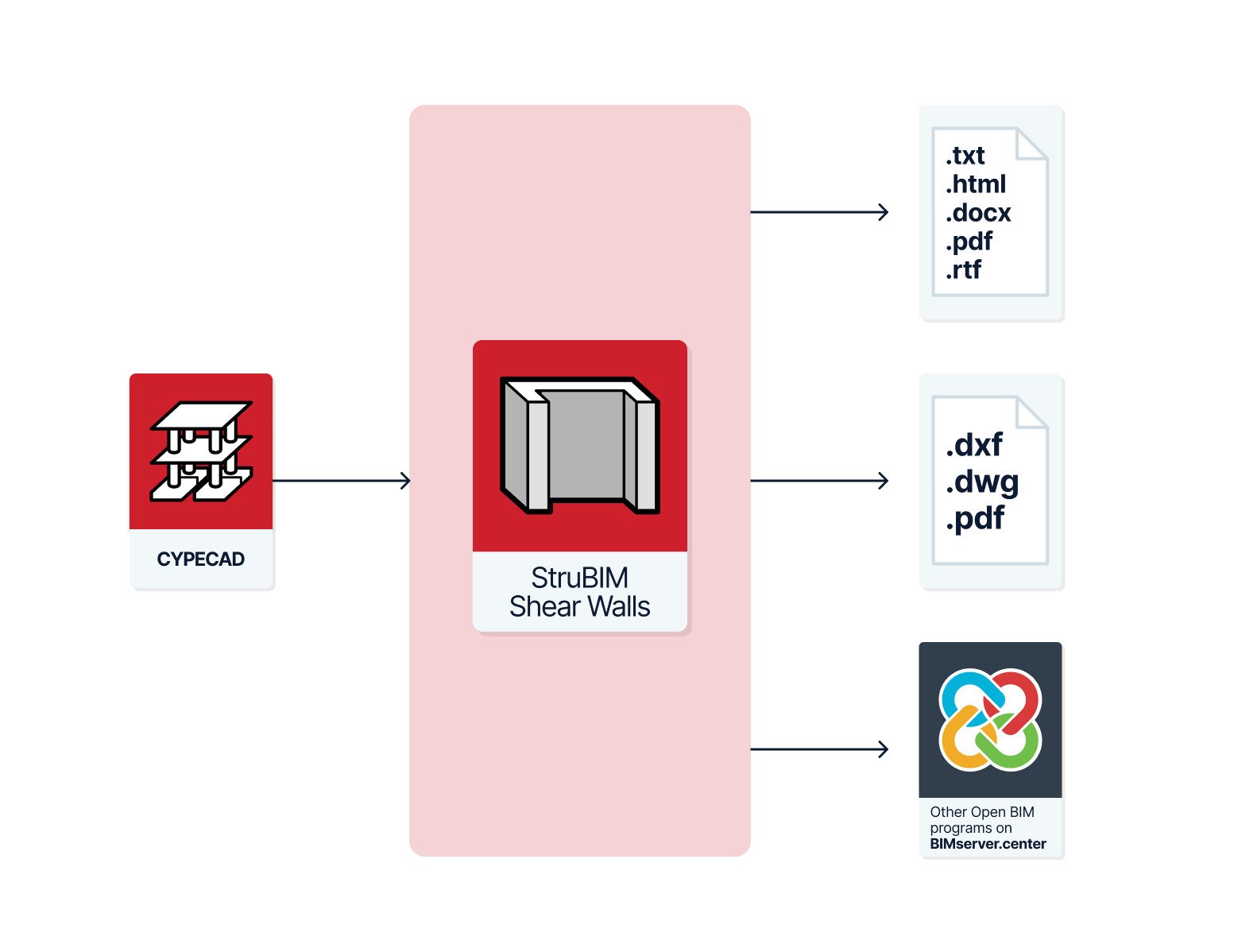
Importing BIM models
If you link the StruBIM Shear Walls module to a BIM project on the BIMserver.center platform, you can perform the following actions:
- Importing building structure models containing information on shear walls and concrete tie beams, including analysis results. This enables the generation of a list of shear walls and tie beams in StruBIM Shear Walls, importing their geometry and internal forces from the information extracted from the model, as well as the deflections of the walls. The import wizard is also capable of retrieving the standard and reinforcement properties selected in the source model. The available options include the following:
- Importing structural models designed in CYPECAD.
Free editing
- Designing and analysing shear walls and/or tie beams by entering and freely editing their details in StruBIM Shear Walls.
Data output
- Exporting reports to HTML, DOCX, PDF, RTF and TXT formats.
- Exporting drawings to DXF, DWG and PDF formats.
- Exporting data generated using StruBIM Deep Beams to the BIMserver.center platform in IFC and glTF formats. This allows authorised project stakeholders to view the data.
Work environment
The StruBIM Shear Walls interface features two tabs, accessible at the top, each with a distinct work environment: "Shear walls" and "Coupling beams".
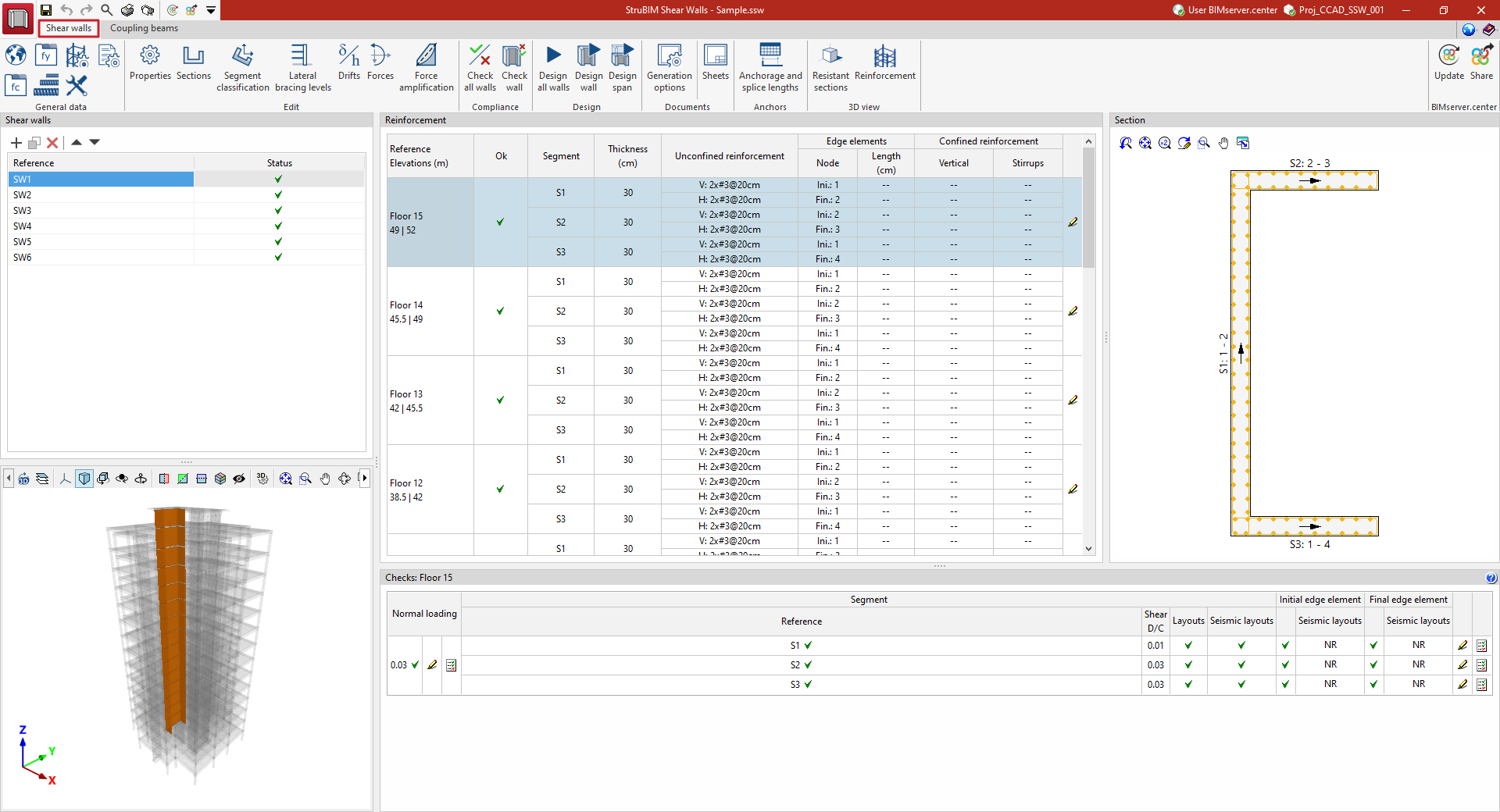
"Shear walls" tab
In the "Shear walls" tab, you can design and check reinforced concrete shear walls.
You can find more information about the options and features on this tab on the following detailed information page:
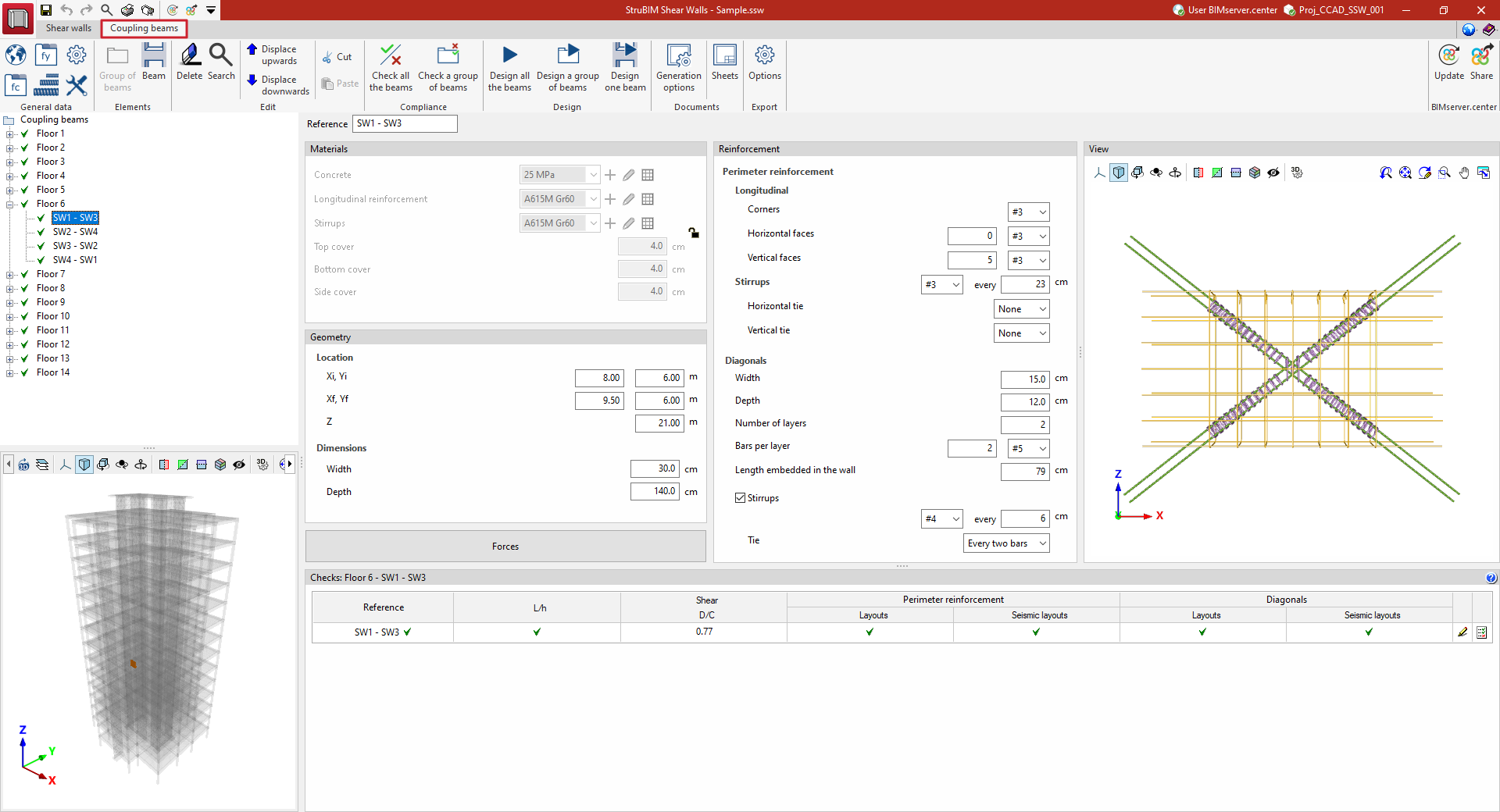
"Coupling beams" tab
In the "Coupling beams" tab, you can design and check reinforced concrete shear walls.
More information about the options and features on this tab can be found on the following detailed information page:
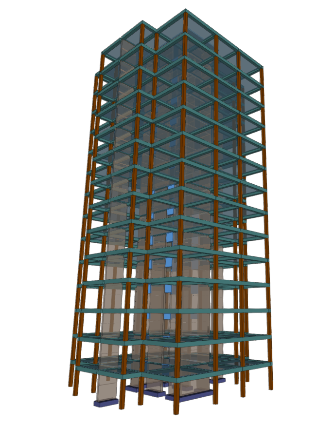
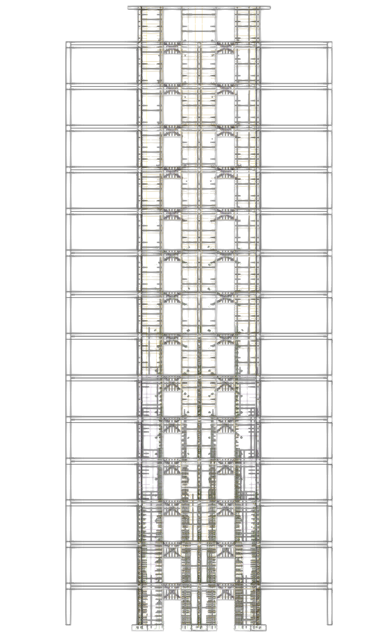
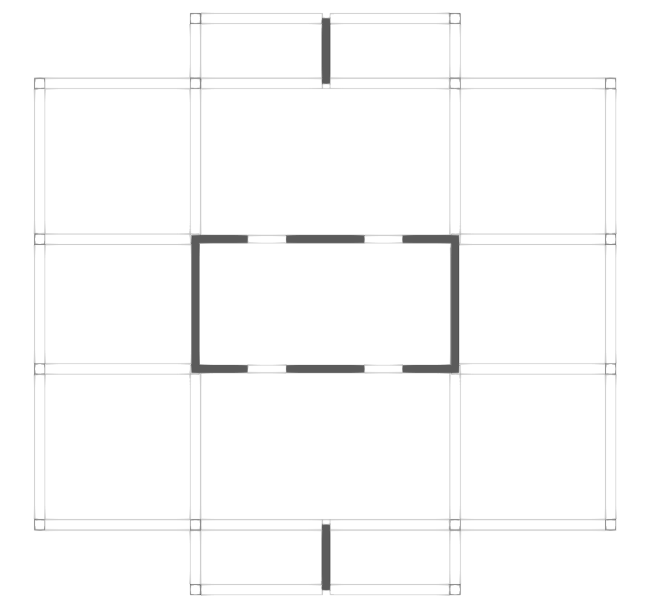
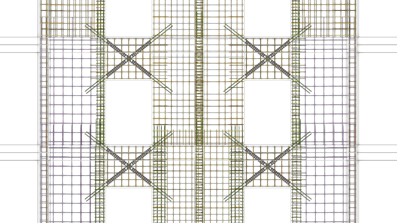
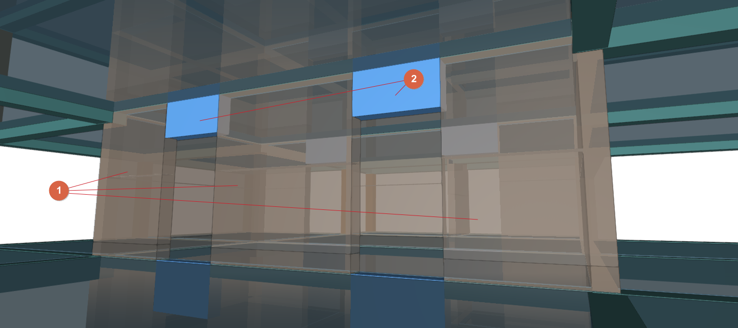
Example of a structure with shear walls and coupling beams
Below is a model of a structure with shear walls and connecting beams that can be checked in the program:
Results output
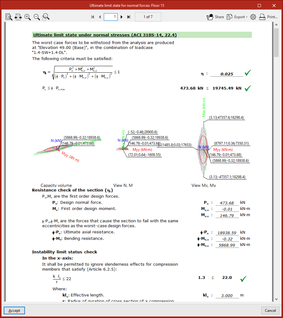
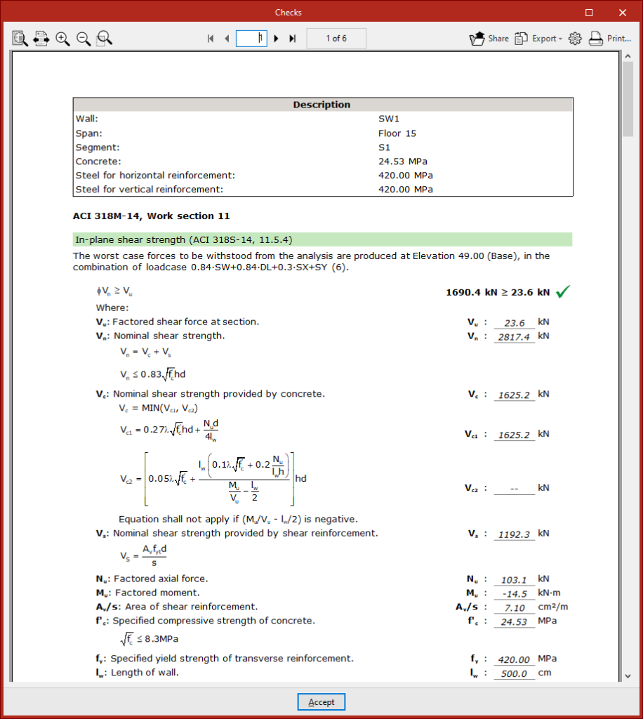
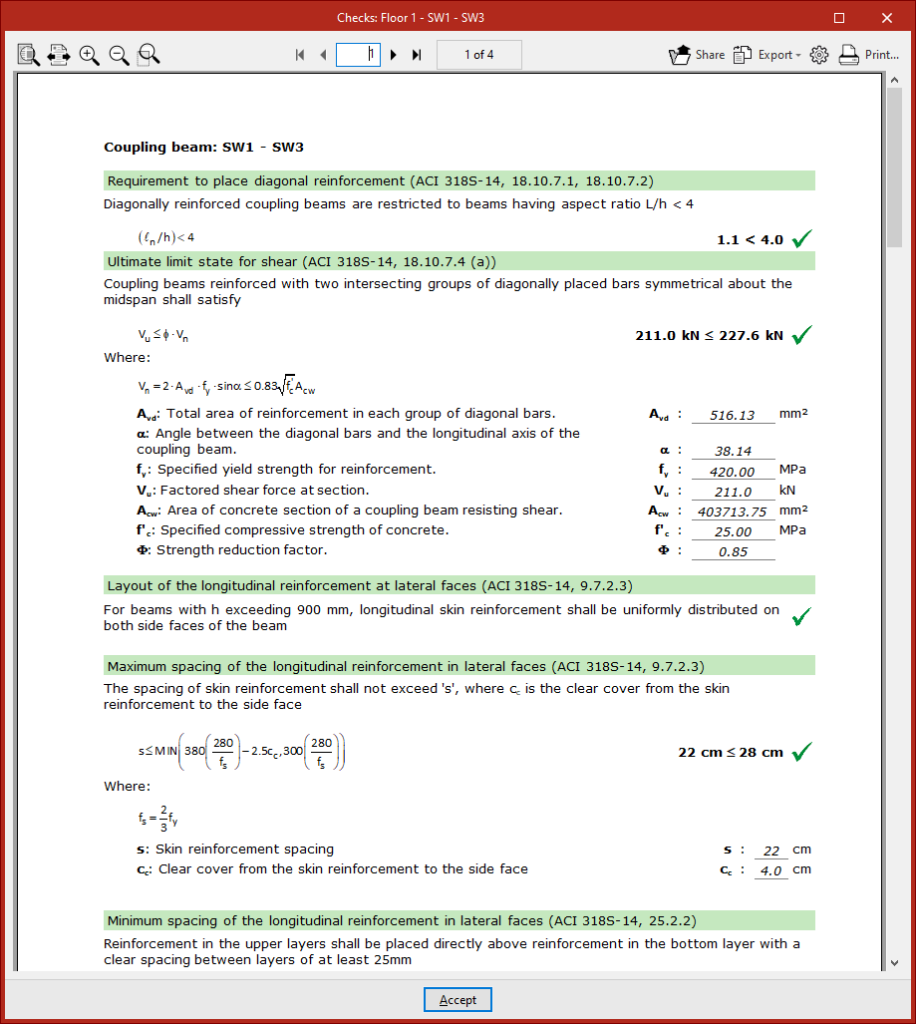
Check reports by element
After analysing each shear wall or coupling beam using the options in the "Check" or "Design" group, detailed on-screen reports of the checks carried out for each element are available
To do this, use the tools available in the checklist at the bottom of the screen.
These reports can be printed directly or exported to HTML, PDF, TXT, RTF or DOCX files.
Project reports
Reports for the project can be generated via the "Reports" option in the "File" menu or from the toolbar at the top left.
The program allows you to print each of these reports directly or generate HTML, PDF, TXT, RTF or DOCX files.
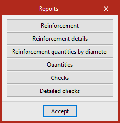
The available reports are as follows:
- Reinforcement
- Reinforcement details
- Reinforcement quantities by diameter
- Quantities
- Checks
- Detailed checks
After selecting a report and clicking "Accept", the program opens a window where you can configure the work sections and/or elements to be included in the list, as well as adjust their numbering.
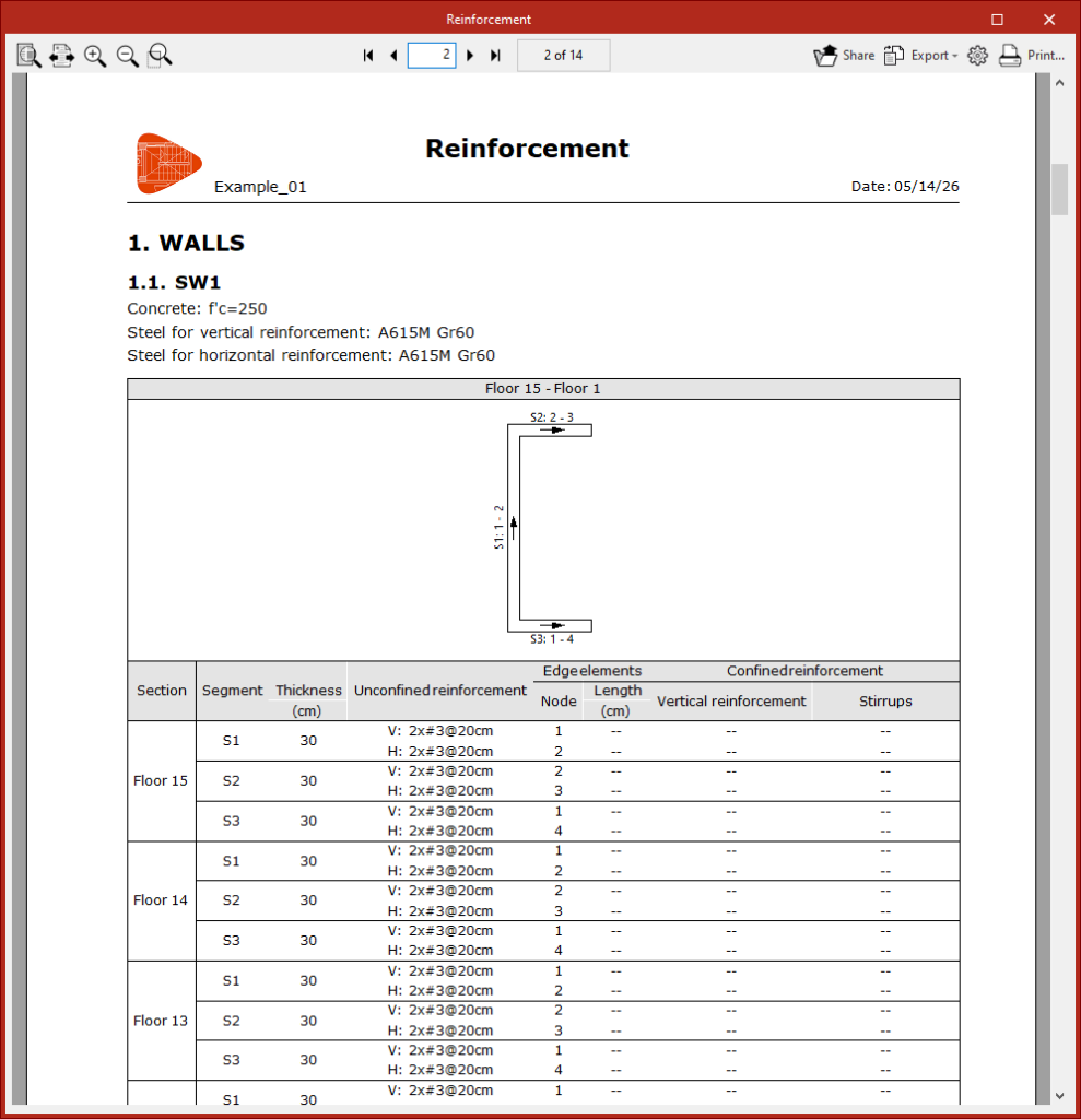
Reinforcement
This report shows information about the reinforcement placed in the shear walls and/or the coupling beams.
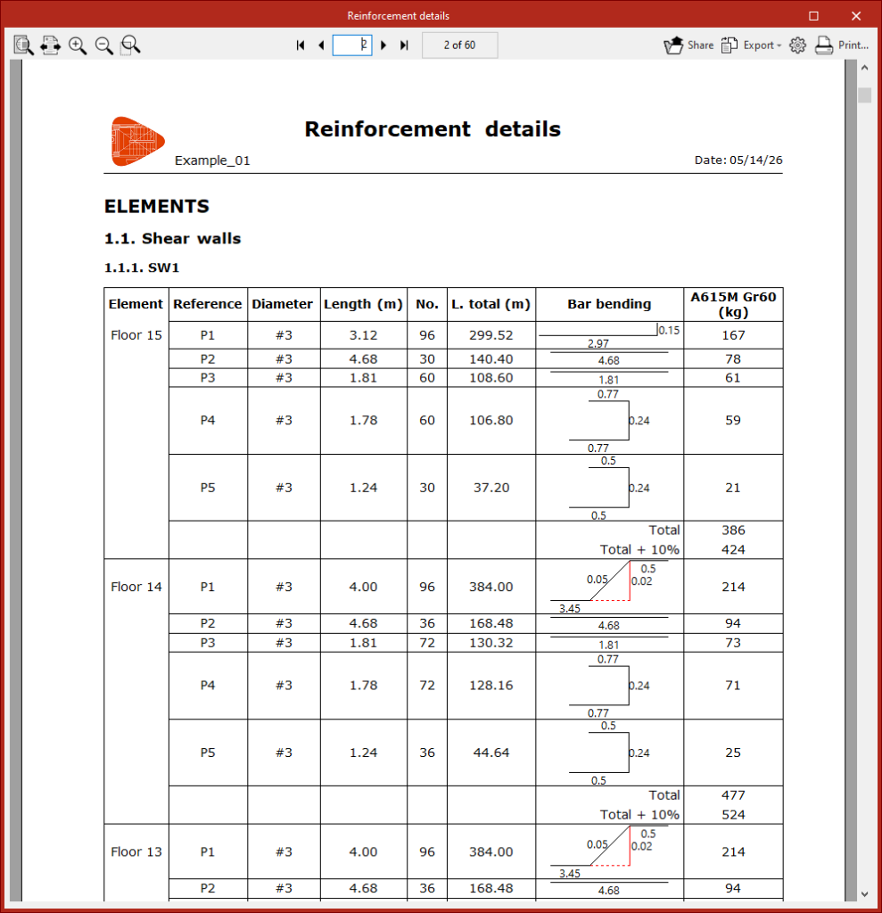
Reinforcement details
This report shows a series of tables containing a detailed breakdown of the bars arranged in the shear walls and/or the coupling beams.
Include the following information for each group of rebars in each element: reference number, diameter, length, number of bars, total length, bending diagram and quantity (weight).
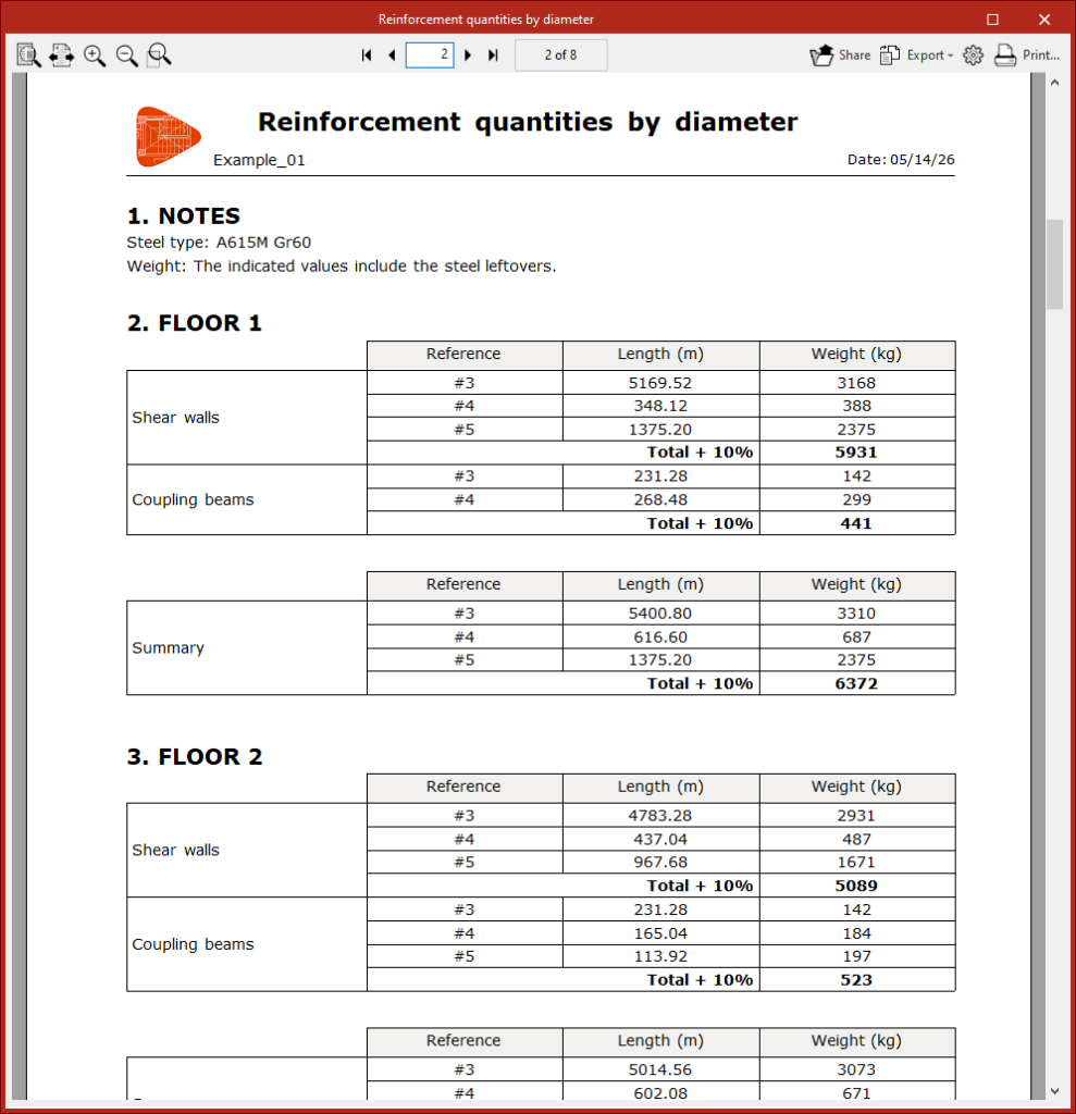
Reinforcement quantities by diameter
This report shows a series of tables detailing the reinforcement quantities for the entire project, organised by floor, type of structural element (shear walls and/or coupling beams), and diameter.
The length and weight of each group of bars of the same diameter are shown.
The total figures for the entire project are also shown.
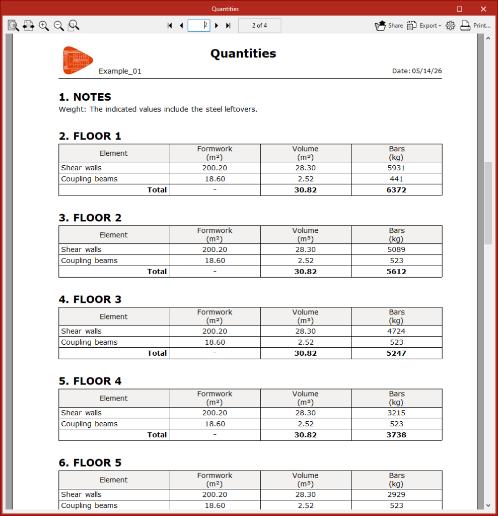
Quantities
This report shows a series of tables detailing the formwork area, concrete volume and weight of reinforcement for each floor, organised by floor and by type of structural element.
The total figures for the entire project are also shown.
| Note: |
|---|
| All weight values in the "Reinforcement quantities by diameter" and "Quantities" tables include steel leftovers. |
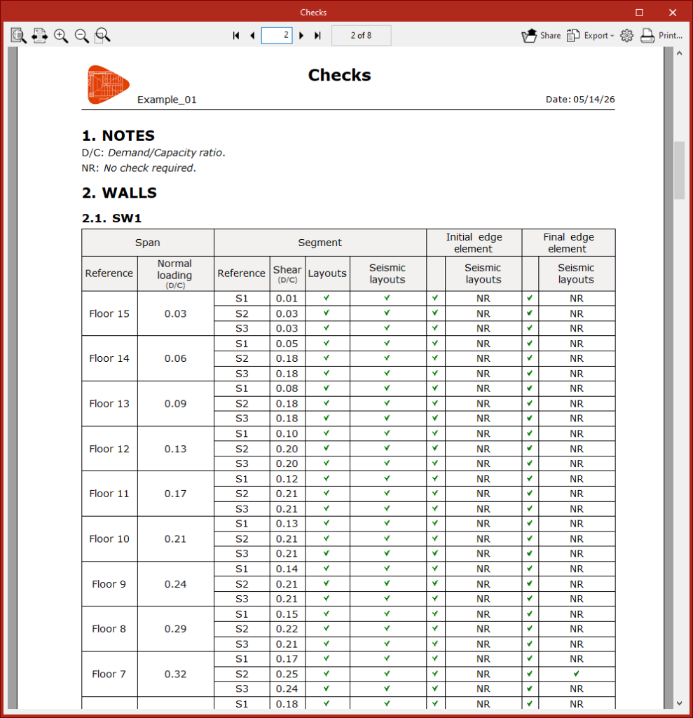
Checks
This report shows a summary of the checks carried out on all elements of the structure.
The compliance status of the shear walls and tie beams with respect to various requirements is shown in a series of tables organised by floor.
Detailed checks
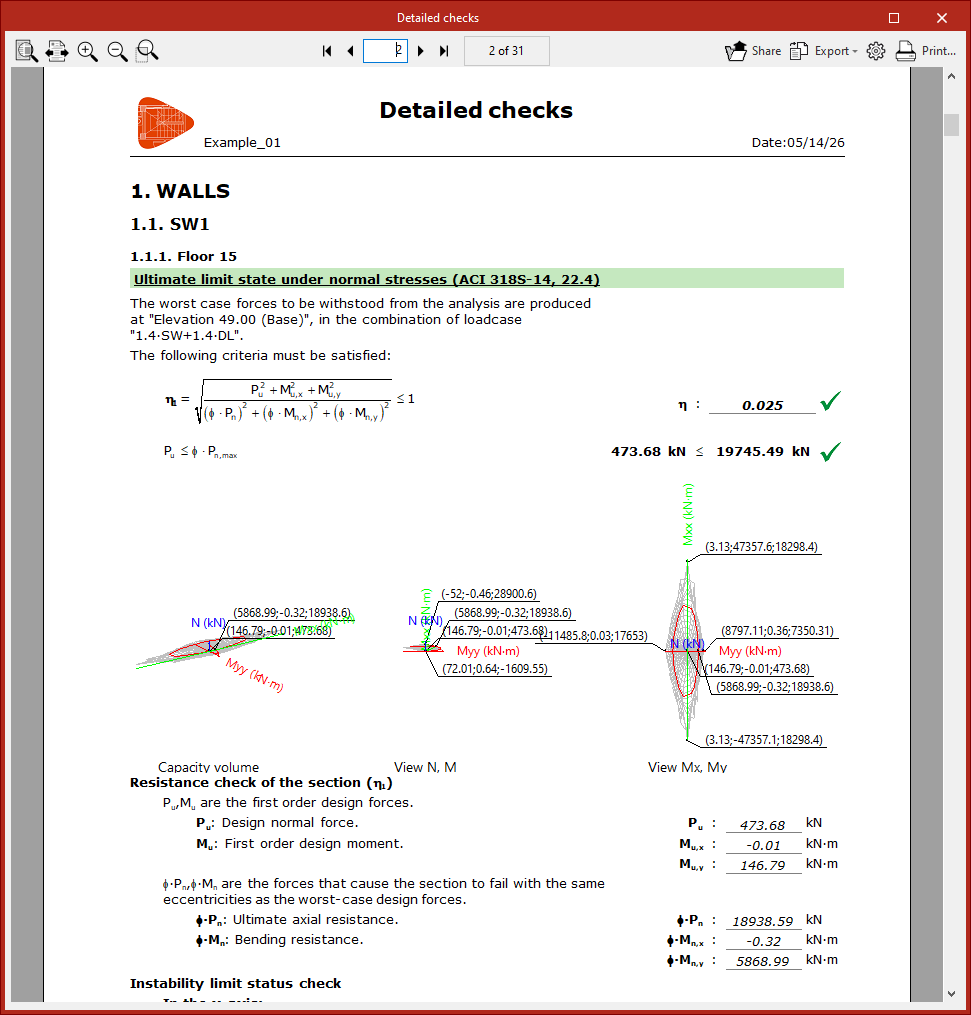
This more comprehensive list provides details of all the checks carried out on all elements of the project.
Each check includes a reference to the relevant regulatory provision, the terms and data used, and the analyses performed by the program.
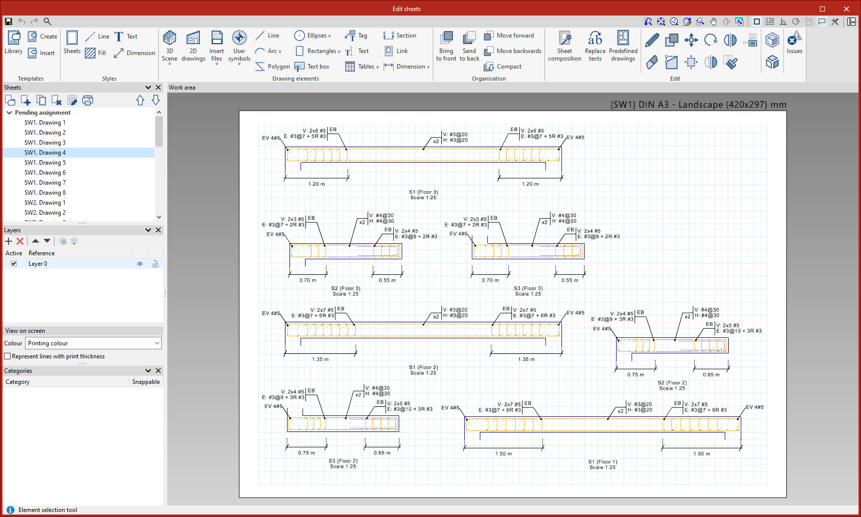
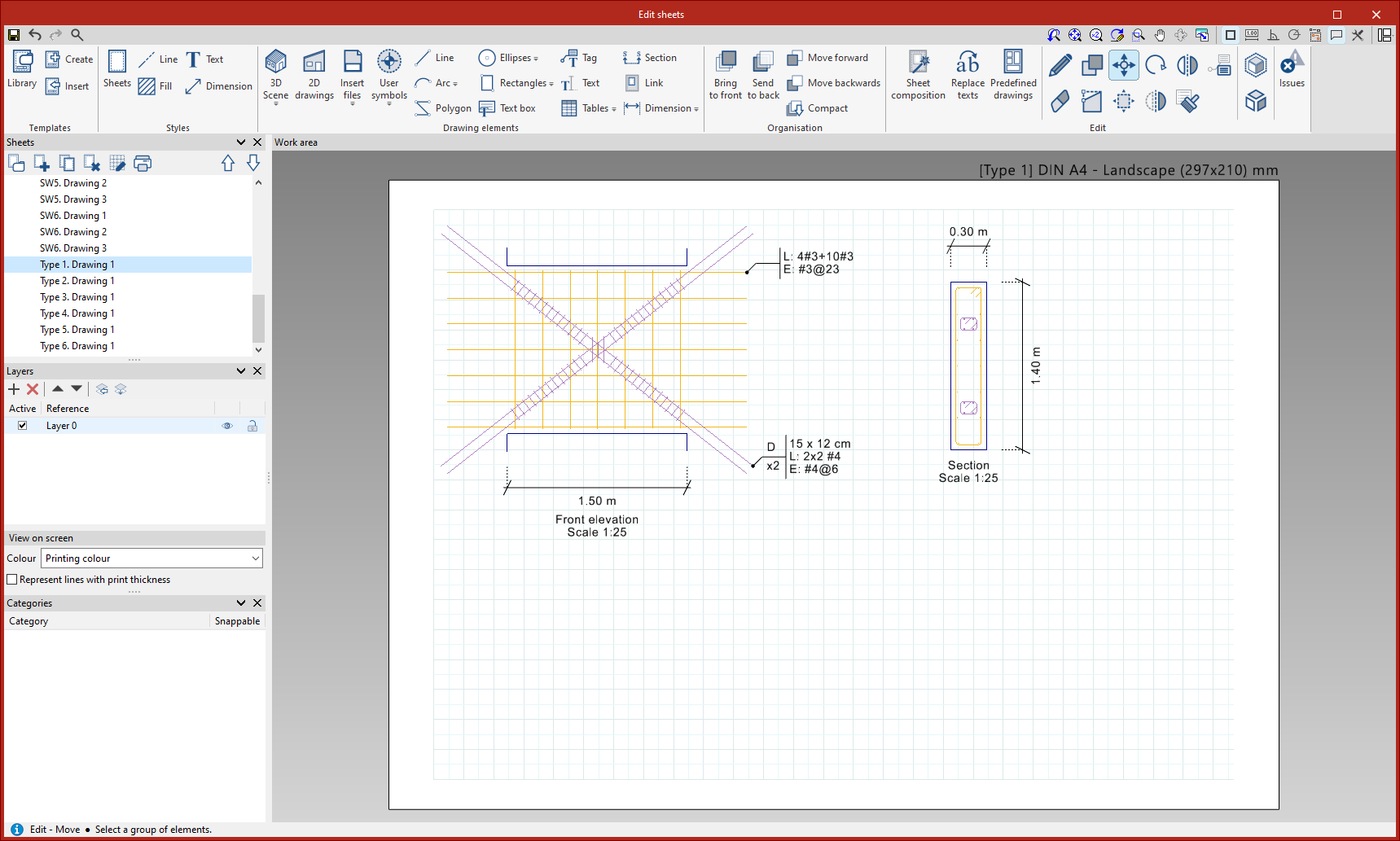
Element drawings
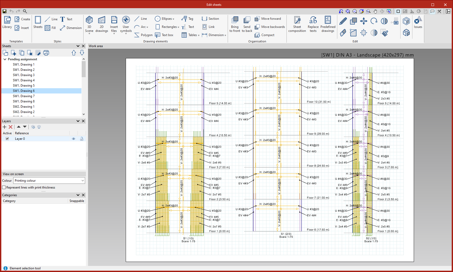
The program allows you to generate, compile and print detailed drawings of each element, organised into sheets, using the tools available in the "Document" section.
The drawings for each element can be printed directly using any graphics device set up on the computer, or you can create DWG, DXF or PDF files.
Project reports
The program allows you to generate, compile and print drawings of all the elements of the project, organised into sheets, using the "Drawings" option in the "File" menu or on the toolbar at the top left.
The project drawings can be printed directly using any printer set up on the computer, or you can create DWG, DXF or PDF files.
IFC file
When the project is exported to the BIMserver.center platform, an IFC file containing information on the analysed reinforcement is exported. In addition, the description of the bars in BVBS format can be integrated into the IFC file, thereby completing the information on the reinforcement detailing.
GLTF files compatible with BIMserver.center
When exporting a project to the BIMserver.center platform, 3D models are also exported in GLTF format, containing information on wall cross-sections, the volumes of load-bearing sections and the reinforcement of the project’s elements, for integration into the Open BIM project, enabling their visualisation:
- On the online platform
- In the BIMserver.center app for iOS and Android
- In virtual reality and augmented reality
- In other CYPE programs
Table of contents
Complete your tour of StruBIM Shear Walls by exploring the other sections available: