Editing shear walls
The "Edit" section of the main toolbar on the "Shear Walls" tab contains options for editing the properties of the shear wall currently selected in the list, including the wall’s geometry, its forces, camber, and bracing levels.

Properties
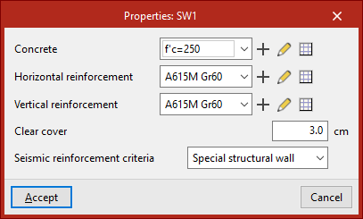
This option opens the "Properties" window, where you can edit the following properties for the shear wall selected in the list:
- Concrete
In this section, you can select and/or edit one of the concrete types created in the specific library. - Horizontal reinforcement
In this section, you can select and/or edit one of the steel types created in the specific library for use in the wall’s horizontal reinforcement. - Vertical reinforcement
In this section, you can select and/or edit one of the steel types created in the specific library for use in the wall’s vertical reinforcement. - Clear cover
Value of the geometric overlap for the wall assembly. - Seismic reinforcement criteria
The program determines the seismic design criteria based on the structural system selected, whether it is an "Ordinary structural wall" or a "Special structural wall".
Sections
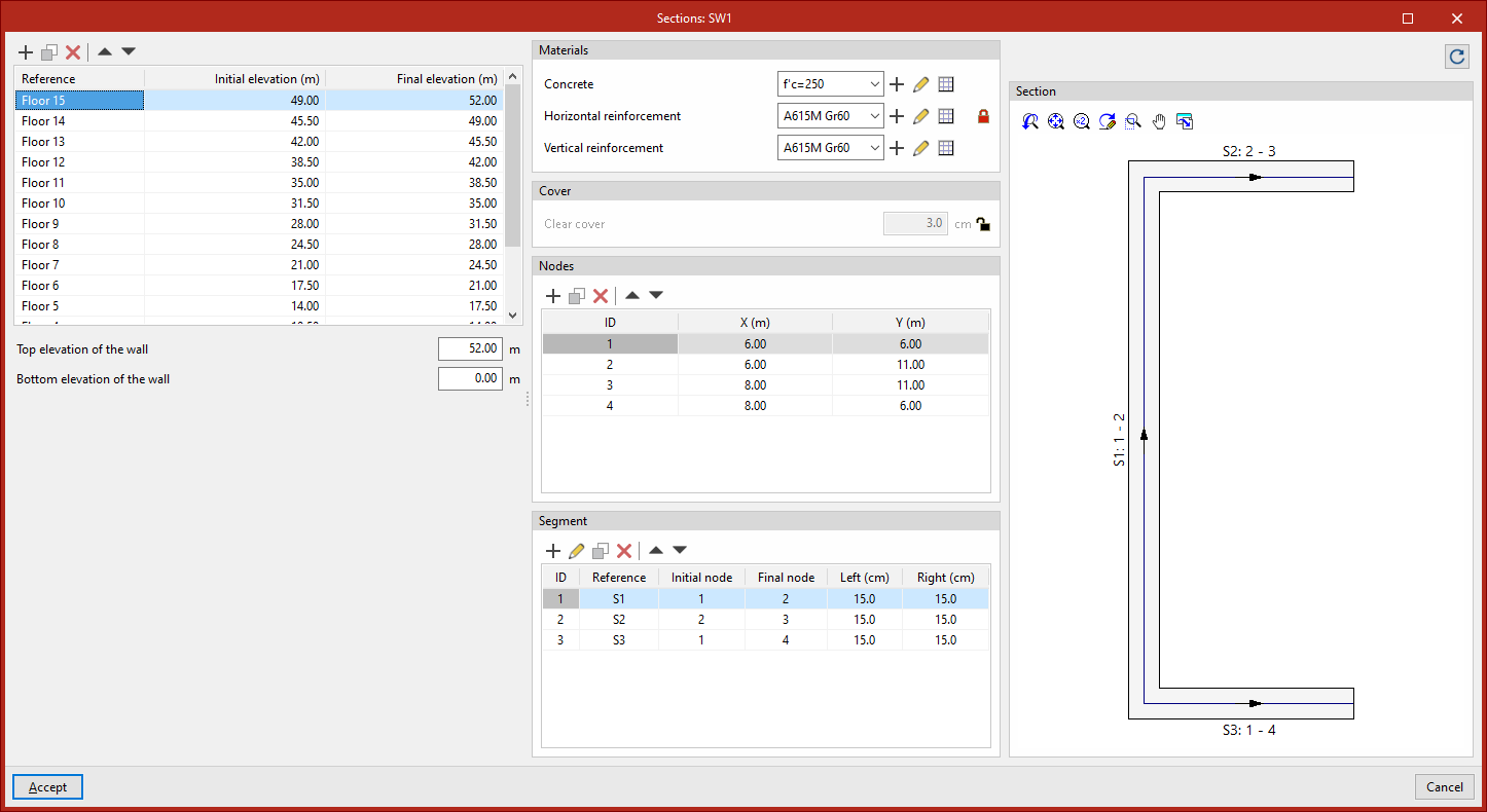
This option opens the "Sections" window, where the following actions can be performed on the shear wall selected from the list, including editing the reinforcement bars that make up each wall and the geometry of its cross-section:
- In the table at the top left, the sections that make up the wall are defined. For each section, you enter its "Reference", "Initial elevation" and "Final elevation".
- The "Top elevation of wall" and "Bottom elevation of wall" are defined below the table.
- The information for each selected section is shown on the right:
- The "Materials" and "Cover" sections retrieve information on the concrete, steel and geometric cover from the previous definition (set via the "Properties" option). These sections can be locked or unlocked by clicking the buttons on the right, should you wish to modify their values for a specific section of wall.
- In the "Nodes" section, the nodes used to define the geometry of the wall section are identified (by their "ID" value) and their position is defined (by their "X" and "Y" coordinates).
- The "Segments" section is used to define the segments that make up the wall section. These are defined by an "ID" value, an editable "Reference", the "Initial node" and "Final node" selected from the list of previously defined nodes, and a "Thickness on the left" and "Thickness on the right" relative to the reference line on the plan view that connects the coordinates of both nodes.
- The "Section" tab displays the plan view of the section defined for the selected span, showing the reference number of each segment and its start and end nodes.
Segment classification
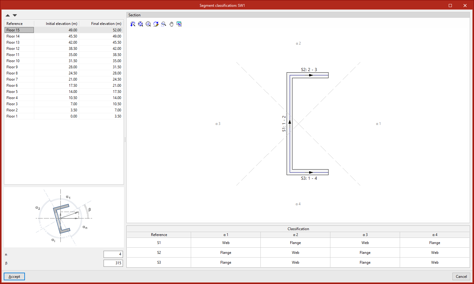
This option opens the "Segment classification" window, where the segments that make up each section of the wall are classified as either a web or a flange, depending on the direction of the horizontal forces acting on them.
This is necessary when designing retaining walls in accordance with different standards for determining the effective cross-sections and the required reinforcement.
The top-left corner of this window displays the list of spans for the selected shear wall. When one of these is selected, a plan view of the "Section" of that span is displayed on the right, and, at the bottom, the "Classification" as a "Flange" or "Web" for the segments of that section at each angular interval (‘α1’, ‘α2’, …, ‘αn’).
The bottom left-hand corner shows a diagram with the following parameters, which are common to all sections of the wall:
- "n" is the number of angular intervals to be considered within which the direction of the horizontal force may lie. Generally, this value is 4. All angular intervals (if there are 4, α1, α2, α3 and α4) are assumed to be equal.
- "β" is the clockwise angle of the start of the first angular interval (α1) relative to the X-axis.
Where a horizontal or seismic force is acting, the segments parallel to that force are regarded as webs, and the perpendicular segments as flanges. If the direction of the force falls within a different angular range, the segments may be treated differently.
The program automatically generates the parameters "n" and "β" based on the wall geometry, as well as the classification of each segment for the resulting angular intervals. Both parameters can be edited; in this case, the program recalculates the classification of the segments.
Furthermore, in the table at the bottom right, you can view and/or modify the "Classification" of the segments in response to forces acting within each angular interval, so that the user can adjust them if deemed necessary in the case of complex geometries.
At least one of the segments must be of the "Web" type in each angular interval.
Lateral bracing levels
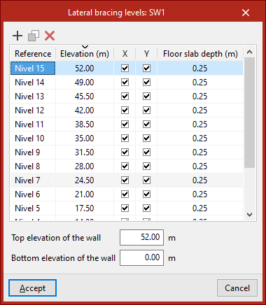
This option opens the "Lateral bracing levels" window, which displays the levels at which the wall is braced in each direction.
You can define the "Reference" for each level, its "Elevation", and specify whether it is braced in the "X" and "Y" directions by ticking the boxes in the relevant column cells. You can also define the "Floor slab depth".
The "Top elevation of the wall" and "Bottom elevation of the wall" are shown at the bottom.
Drifts
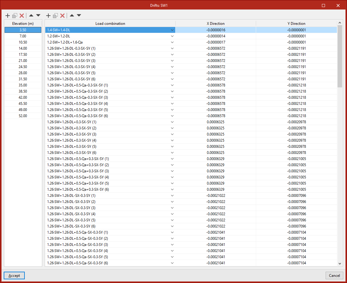
This option opens the "Drifts" window, which displays and allows you to edit the drifts of the selected shear wall.
On the left-hand side, a list is displayed showing the "Elevation" at which the overhangs are defined. On the right-hand side, a list is displayed showing the wall overhangs at the selected elevation in the "X direction" and "Y direction" directions for each "Load combination".
The program retrieves this data during the initial import process from the analysis results included in the BIM model.
Forces
This option opens the "Loads" window, which displays and allows you to edit the loads acting on the selected shear wall.
Table of forces
In the top-left corner is the "Table of forces" button. This opens a table where, for each "Location" ("Base", "Head" or "Other"), "Elevation" and "Load combination", you can specify whether it is a "Seismic action" or not (by ticking the relevant box), the values of the axial force ("N"), the shear forces in both directions ("Vx", "Vy"), the torsional force ("T"), and the bending moments in both directions ("Mx" and "My").
The forces are defined in general directions relative to the centre of gravity of the shear wall. The sign convention can be found in the diagram accessible via the "Help" button at the top.
The program retrieves this data during the initial import process from the analysis results included in the BIM model.
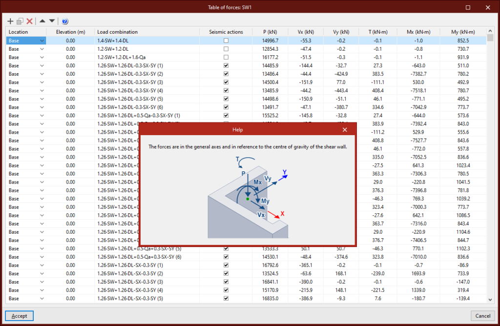
Displaying forces
The main window that appears when you click on the "Forces" option displays a graphical representation of the selected forces.
In the "View" section on the left-hand side, you can configure this view:
- Firstly, you can select the "Initial" and "Final" sections that you wish to display.
- Next, the "Selection of forces" is carried out. To do this:
- Tick this box if you want to display the forces With automatic scale calculation" according to the zoom level.
- Next, in the table, tick each "Force" that you want to make "Visible", and enter its "Scale". The program displays the colour for each effort.
- Below, select the set of loadcases to be displayed.
- Finally, in the "Settings" options, tick the boxes to "View values" by hovering the cursor over each stress-strain curve, "Show maximum values" on each graph, or "Draw the stress-strain curve filled in" with colour.
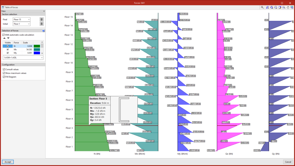
Force amplification
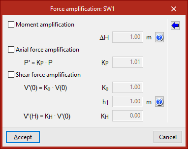
This option opens the "Force amplification" window, which allows you to set the amplification of the moments, axial forces and shear forces for the selected shear wall as follows:
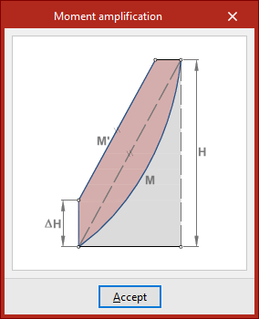
- "Moment amplification" is defined by the parameter "ΔH", which is used to derive the law of amplified moments.
- The "Axial force amplification" is determined by the parameter "KP", such that the amplified axis is equal to P' = KP·P
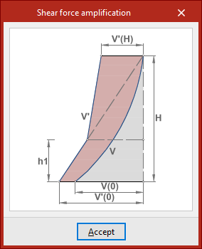
- "Shear force amplification" is defined by the parameters "K0", "h1" and "KH", which determine the amplified shear law such that V'(0) = K0·V(0) and V'(H) = KH·V'(0)
The program provides helpful diagrams to make these parameters easier to understand.