Configuring general data for the design of shear walls
In the "General data" section of the main toolbar on the "Shear walls" tab, you will find options for configuring the following general project data:

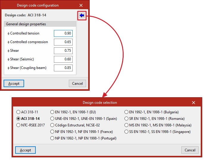
Design code configuration
This option opens a pop-up window where you can select the code the program will use for the design.
To do this, click the button on the right and select the standard or combination of standards from those available in the program.
In addition, at the bottom of this window, you can adjust the values of various parameters relating to the selected standard.
| Note: |
|---|
| The codes implemented in CYPE's programs can be viewed via the following link. |
Concrete
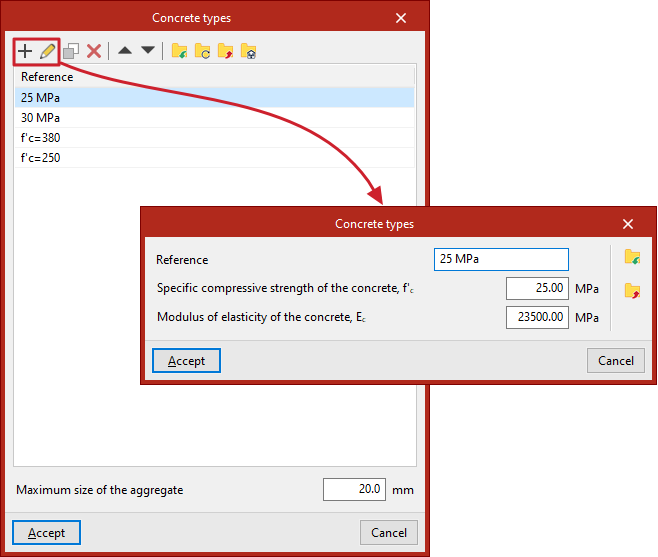
This option allows you to access the concrete type library. For each concrete type, you must define the following parameters:
- Reference
- Specific compressive strength of the concrete, fck
- Modulus of elasticity of the concrete, Ec
Concrete types can be added from scratch by the user, imported and/or exported to .bibgen files saved to disk, or created using the wizard from the "Predefined" concrete types available in certain standards for each country or region. To do this, use the tools at the top of the list of types.
You can also set the "Maximum size of aggregate" in the relevant field in this window.
Steels
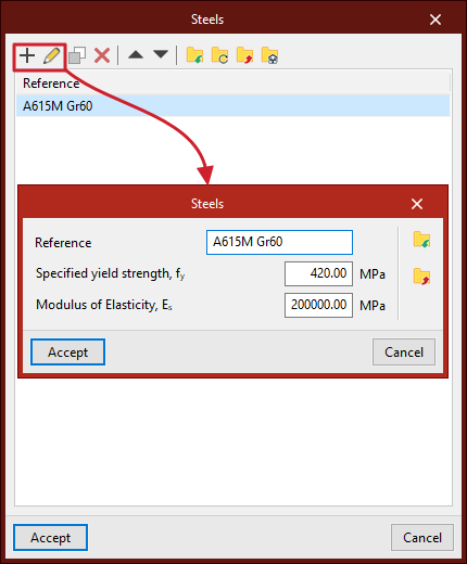
This option allows you to access the library of rebar types. For each type of rebar, you must define the following parameters:
- Reference
- Specified yield strength, fyk
- Modulus of elasticity, Es
Steel grades can be added from scratch by the user, imported and/or exported to .bibgen files saved to disk, or created using the wizard from the "Predefined" steels available in certain standards for each country or region. To do this, use the tools at the top of the grade list.
Reinforcement layout criteria
This option opens a window where you can configure the various reinforcement layout criteria for shear walls and tie beams, which the program will use in the design calculations.
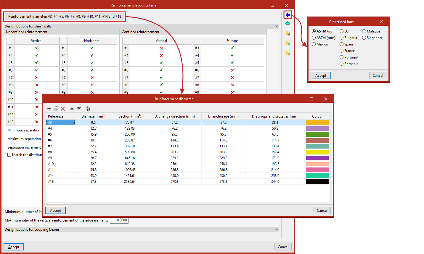
Firstly, the button at the top opens a dialogue box where you can add the available "Reinforcement diameters". The "Predefined bars" button on the right allows you to load this information based on the selected standard, region or country.
On the right-hand side, the program also offers a feature that "Restores the default installation values", as well as tools for exporting or importing the information defined in this window to .bib548 files on the hard drive.
The design options for shear walls and/or connecting beams are configured later in various drop-down sections:
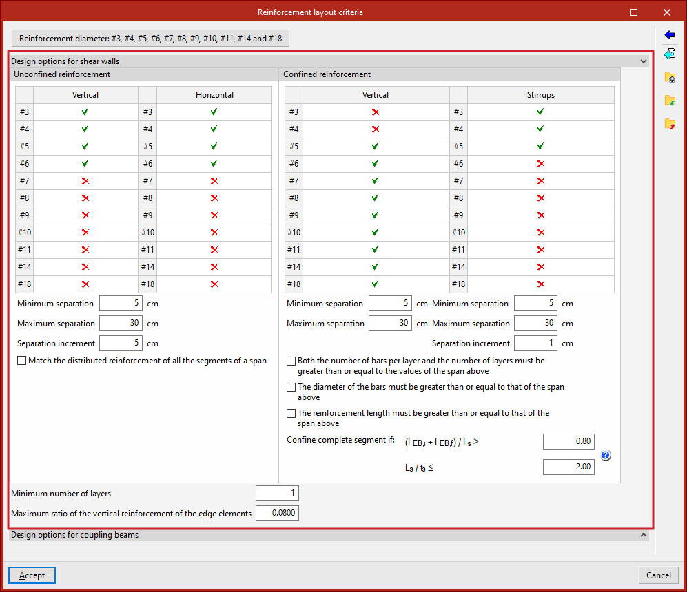
Design options for retaining walls
- Unconfined reinforcement (Vertical, Horizontal)
This table allows you to select or deselect the bar diameters or sizes that the program may or may not use in the unconfined reinforcement of shear walls. You can subsequently adjust the following parameters for this reinforcement:- Minimum spacing
- Maximum separation
- Increased spacing
- Align the distributed reinforcement of all segments in a span (optional)
- Confined reinforcement (Vertical, Stirrups)
Selects or deselects the bar diameters or sizes that the program may or may not use in the confined reinforcement of shear walls. You can subsequently adjust the following parameters for this reinforcement:- Minimum separation (vertical reinforcement)
- Maximum separation (vertical reinforcement)
- Minimum clearance (brackets)
- Separation increment (stirrups)
- Increased separation (stirrups)
- Both the number of bars per layer and the number of layers must be greater than or equal to the corresponding values for the upper section (optional)
- The diameter of the bars must be greater than or equal to that of the upper section
- The length of the reinforcement must be greater than or equal to that of the upper section
- Confine entire segment (the parameters LEB,i, LEB,f, Ls and ts are detailed in the help diagram on the right):
- (LEB,i + LEB,f)/Ls ≥ [value]
- Ls / ts ≤ [value]
In addition, the "Minimum number of layers" and the "Maximum amount of vertical reinforcement for edge elements" are specified.
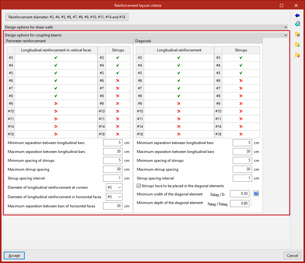
Design options for connecting beams
- Perimeter reinforcement (longitudinal reinforcement on vertical faces, stirrups)
This table allows you to select or deselect the bar diameters or sizes that the program may or may not use in the perimeter reinforcement of the connecting beams. You can subsequently adjust the following parameters for this reinforcement:- Minimum separation between longitudinal bars
- Maximum separation between longitudinal bars
- Minimum spacing of stirrups
- Maximum spacing interval
- Stirrup spacing interval
- Diameter of the longitudinal reinforcement at corners
- Diameter of the longitudinal reinforcement in horizontal faces
- Maximum spacing between horizontal face bars
- Diagonals (Longitudinal reinforcement, Stirrups)
This table allows you to select or deselect the bar diameters or sizes that the program may or may not use in the diagonal reinforcement of the coupling beams. You can subsequently adjust the following parameters for this reinforcement:- Minimum spacing between longitudinal bars
- Maximum spacing between longitudinal bars
- Minimum distance between stirrups
- Maximum distance between footrests
- Spacing between stirrups
- Brackets should be fitted to the diagonal members (optional)
- Minimum width of the diagonal member, bdiag/b
- Minimum height of the diagonal element, hdiag/bdiag
(the parameters bdiag, hdiag and b are explained in the help section on the right)
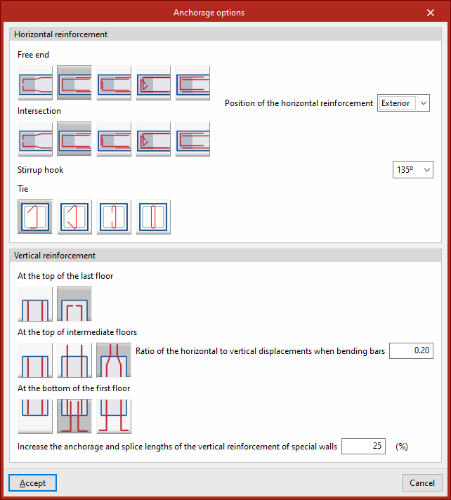
Anchorage options
From here, you can adjust the anchorage geometry of the shear wall bars for both the horizontal and vertical reinforcement.
In the case of "Horizontal reinforcement", the program offers the following options:
- For the "Free end" and the two-segment "Intersection", the following is possible:
- "Extend" the reinforcement, specifying the type of "Hook" ("None", "90°", "135°" or "180°") and the "Horizontal reinforcement position" ("Exterior" or "Interior");
- Use "Loops", specifying the "Position of the horizontal reinforcement" ("External" or "Internal");
- Use "Bars at 90°", specifying the "Position of the horizontal reinforcement" ("Outer" or "Inner");
- Specifies a "Horizontal reinforcement up to the end of the segment, anchored in the opposite layer", indicating the type of "Hook" ("None", "90°", "135°" or "180°");
- Or provide "Horizontal reinforcement up to the end of the segment, spliced with hook".
- The "Stirrup hook" can be set to "90°" or "135°", whilst the "Tie" can be "with 90° and 135° hooks", "with 135° and 135° hooks", "With 180° hooks" and "180°" or "Closed".
In the case of "Vertical reinforcement", the program offers the following options:
- "At the top of the last floor", the bars can be installed either "without anchoring" or "with leg anchoring".
- "At the top of the intermediate floors", the bars may be arranged "without anchoring", "with anchoring in a straight extension" or "with anchoring in a straight extension with a joint" (in which case the "ratio between the horizontal and vertical displacements at the bar joint" must be specified).
- "At the bottom of the first floor", the bars can be arranged "Without anchoring", "With spares" or "With anchoring".
In all cases, it is possible to "Increase the anchorage and lap lengths of the vertical reinforcement for special walls" by the percentage specified in the relevant field.
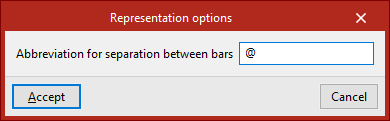
Representation options
From here, you can configure the symbol for the "Abbreviation for separation between bars" (by default, '@') used to represent reinforcement in drawings.
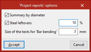
'Project reports' options
By ticking the relevant boxes, you can include the "Summary by diameter" in the site lists, as well as the "Steel leftovers", specifying the percentage.
You can also adjust the "Text size for 'Bar bending'".