

Defining materials, geometry and reinforcement for coupling beams
The "Materials", "Geometry" and "Reinforcement" panels, located in the centre of the interface, allow you to adjust the materials, view the geometry and edit the reinforcement layout for the coupling beams selected from the list on the left-hand side.
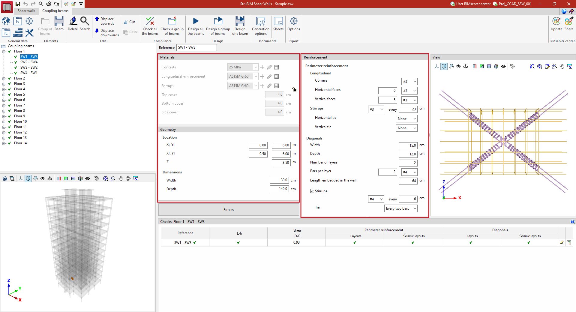
Materials
This panel shows the "Concrete" used in the selected coupling beams, the steel used in the "Longitudinal reinforcement" and the "Stirrups". It also indicates the "Top cover", the "Bottom cover" and the "Side cover" of the reinforcement bars arranged in the beam.
By default, the program retrieves this information from the settings defined under the "Properties" option in the "General data" section, which applies to all beams in the project.
In any case, you can click on the "Lock/unlock the values of material" option, located to the right of this section, to unlink these values from the general settings and edit them individually for each beam.
Geometry
This panel allows you to modify the geometry of the selected coupling beam and displays the following information:
- Position
Global plan coordinates of the start point ("Xi", "Yi") and the end point ("Xf", "Yf") of the coupling beams, as well as its global "Z" coordinate. - Dimensions
Width and depth of the coupling beam.
The program retrieves this data during the initial import process from the information in the BIM model.
Reinforcement
- Perimeter reinforcement
Definition of the perimeter reinforcement for the tie beam, comprising:- Longitudinal
The longitudinal reinforcement includes the four "Corner" bars, for which the diameter is selected, and the additional bars on the "Horizontal faces" and "Vertical faces", for which the number of additional bars per face is entered and the diameter is selected. - Stirrups
The diameter and spacing of the stirrups are defined. The “Horizontal tie” and “Vertical tie” patterns for the longitudinal reinforcement bars are also specified, either as “All tied” or “None”.
- Longitudinal
- Diagonals
The reinforcement diagonals for the coupling beam are defined. To do this, specify the "Width", "Thickness", "Number of layers", and the number of "Bars per layer", as well as their diameter.
In addition, enter the "Length embedded in the wall" adjacent to the coupling beam.
Finally, tick the "Stirrups" box if the diagonal has them, selecting their diameter and spacing, as well as the "Tie" pattern for the diagonal bars ("All tied", "Every two bars" or "None").
