

Defining shear wall reinforcement
The "Reinforcement" panel, located in the centre of the interface, allows you to view and edit the layout of the reinforcement in the shear wall selected from the list on the left-hand side.
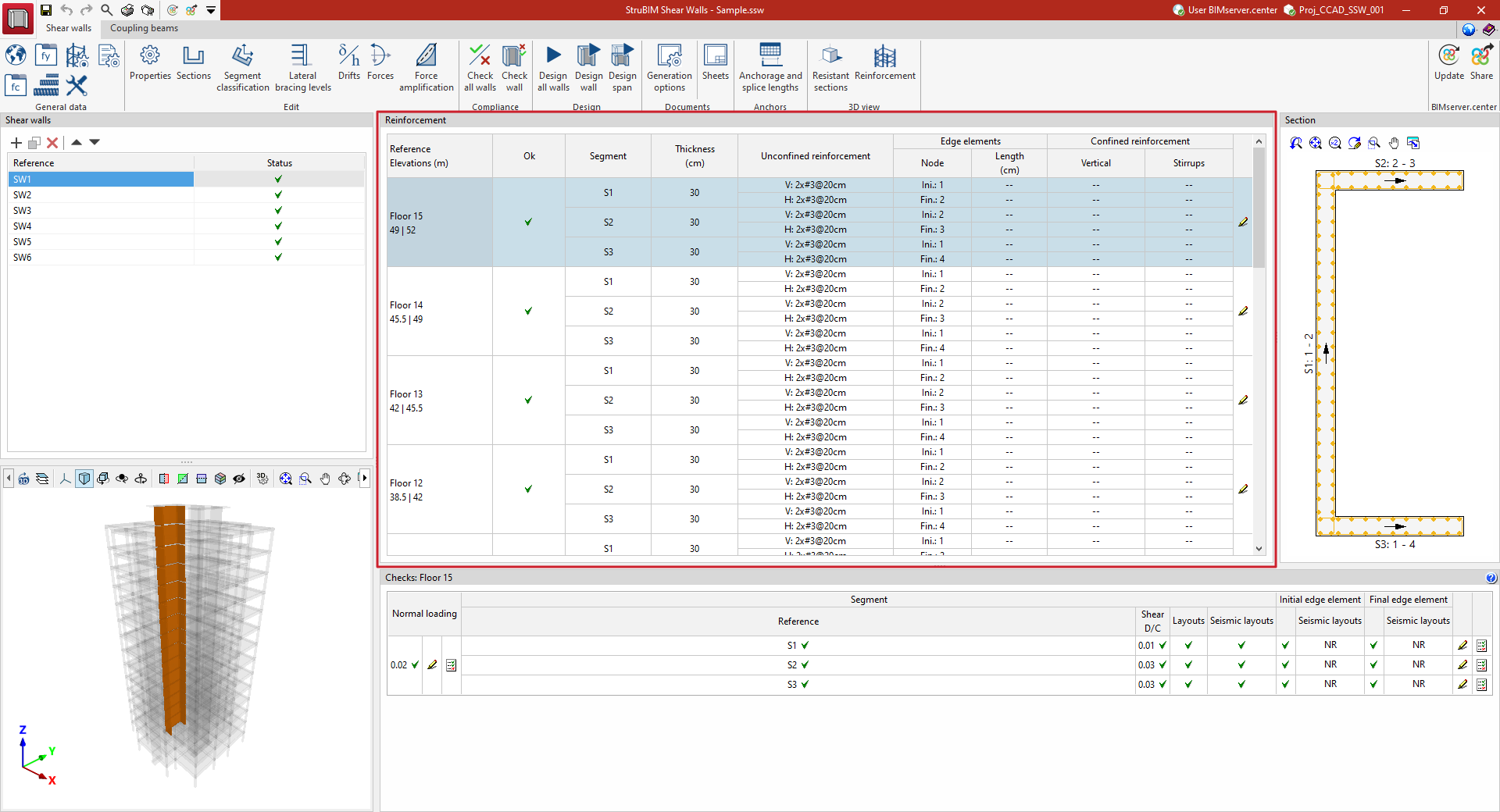
This panel displays a table with the following columns:
- Reference - Dimensions
Reference for the reinforcement section of the shear wall, together with the associated start and end dimensions. These sections can be configured via the "Sections" option in the top toolbar. - Verified
Indicates whether the section does or does not comply with regulatory checks, or whether verification is pending, using the options in the "Compliance" and/or "Design" sections. - Segment
Reference for the various segments that make up the section of the span. The segments can be configured via the "Sections" option in the top toolbar. - Thickness
The thickness of each of the segments that make up the section of the span. The thickness is the sum of the thicknesses to the left and right of the segment, which can be configured via the "Sections" option in the top toolbar, or via the "Edit" option on the right-hand side of the "Reinforcement" panel. - Unconfined reinforcement
Unconfined reinforcement for the segment. The number of layers, diameter and spacing of the vertical ('V') and horizontal ('H') bars are shown. This reinforcement can be modified using the "Edit" option on the right-hand side of the "Reinforcement" panel. - Edge elements
Indicates whether there are any edge elements with confined reinforcement at any of the nodes (start or end) of the segment. The "Node" identifier and the "Length" of the edge element on the segment are displayed, together with the thickness of the adjacent segment. The presence of edge elements with confined reinforcement can be specified using the "Edit" option on the right-hand side of the "Reinforcement" panel. - Confined reinforcement
Confined reinforcement within the segment, or within each edge element defined at the start and/or end nodes of the segment. The number of layers, the number of bars, and the diameter of the vertical reinforcement bars are displayed, as well as the diameter and spacing of the stirrups. This reinforcement can be modified using the "Edit" option on the right-hand side of the "Reinforcement" panel.
Editing armatures
The "Edit" option, located to the right of the "Reinforcement" panel for each section of the wall, allows you to edit the reinforcement for that section. Clicking on this option opens a window displaying a table with the following columns:
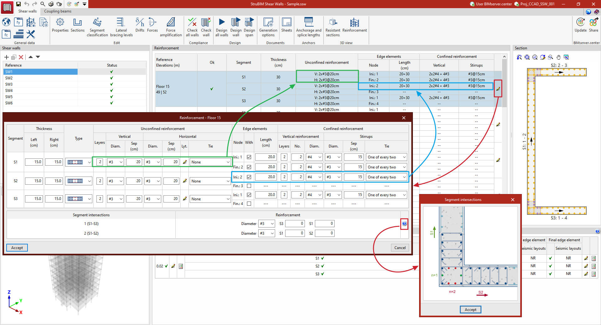
- Segment
Reference for the various segments that make up the section of the stretch. - Thickness (Left, Right)
Configurable values for the thickness on the left and right of the segment. - Type
Specifies whether the main reinforcement of the segment is unconstrained or constrained. - Unconfined reinforcement
Defines the unconfined reinforcement for the segment. This is determined by the following parameters:- Layers
The number of layers or reinforcement planes in the unconstrained reinforcement. This number can be 1 (a single central reinforcement plane), 2 (two reinforcement planes on both faces of the segment) or 3 (three reinforcement planes in the centre and on both faces of the segment). - Vertical
Select the diameter and enter the spacing of the bars in the unconstrained vertical reinforcement. - Horizontal
Select the diameter and enter the spacing of the bars in the unconfined horizontal reinforcement. The following is also defined:- The "Horizontal reinforcement position", whether "external" or "internal",
- The "Tie" ("All" the bars, "Every other one", "Every third one", "Every fourth one", "Every fifth one", or "None" of the bars).
- Layers
- Edge element
Indicates the presence of edge elements with confined reinforcement (where a non-confined main reinforcement has been defined). The "Node" column shows the start and end nodes of each segment. To indicate the presence of such elements, tick the box in the next column (“With edge element”). Enter the length of the edge element on the segment being edited. - Confined reinforcement
Defines the confined reinforcement for the segment (if confined main reinforcement has been defined or if edge elements have been declared). This is determined by the following parameters:- Vertical
Number of layers or reinforcement planes, selection of diameter and entry of the spacing of the bars in the confined vertical reinforcement. - Stirrups
Selects the diameter and specification of the spacing of the stirrups in the confined reinforcement. In addition, their "Tying" is specified ("All" bars, "One in two", "One in three", "One in four", "One in five", or "None" of the bars).
- Vertical
At the bottom of the window, you can define additional reinforcement for each "Segment intersection". You must specify the "Diameter" and the number of bars to be added per reinforcement plane in the direction of each of the two segments at the junction. The program displays a help diagram, accessible via the button on the right, to aid understanding of these parameters.
After clicking "Accept" in the editing window for each reinforcement section, the program will display this information in the "Reinforcement" panel and update the "Section" view of the wall on the right-hand side of the interface.
