As of version 2025.a, the CYPE plugins for Revit "Plugin Open BIM - Revit" and "Plugin MedBIM - Revit" (the latter included in the Arquimedes module "Bill of quantities of BIM models") are compatible with Revit version 2025.
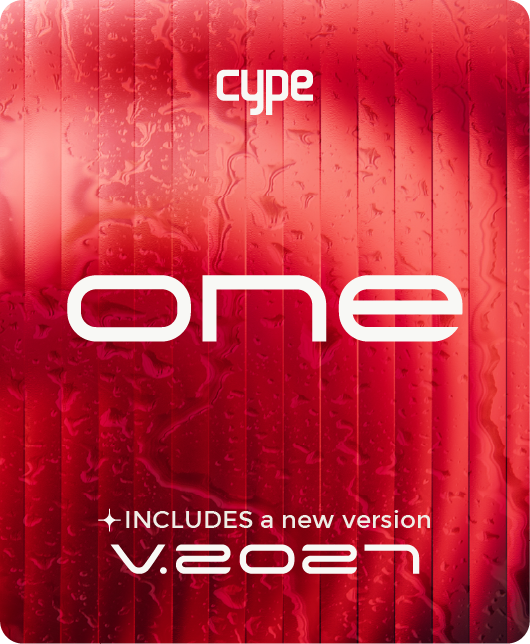
"About..." option
An "About..." option has been added to the "Open BIM - Revit Plugin" menu to consult the plugin information and its version.
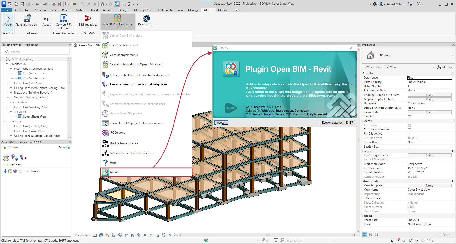
Sharing the Revit® model
In the "Share the Revit model" option, the "Description" field has been implemented so that users can provide a description when sharing the Revit job with a BIMserver.center project.
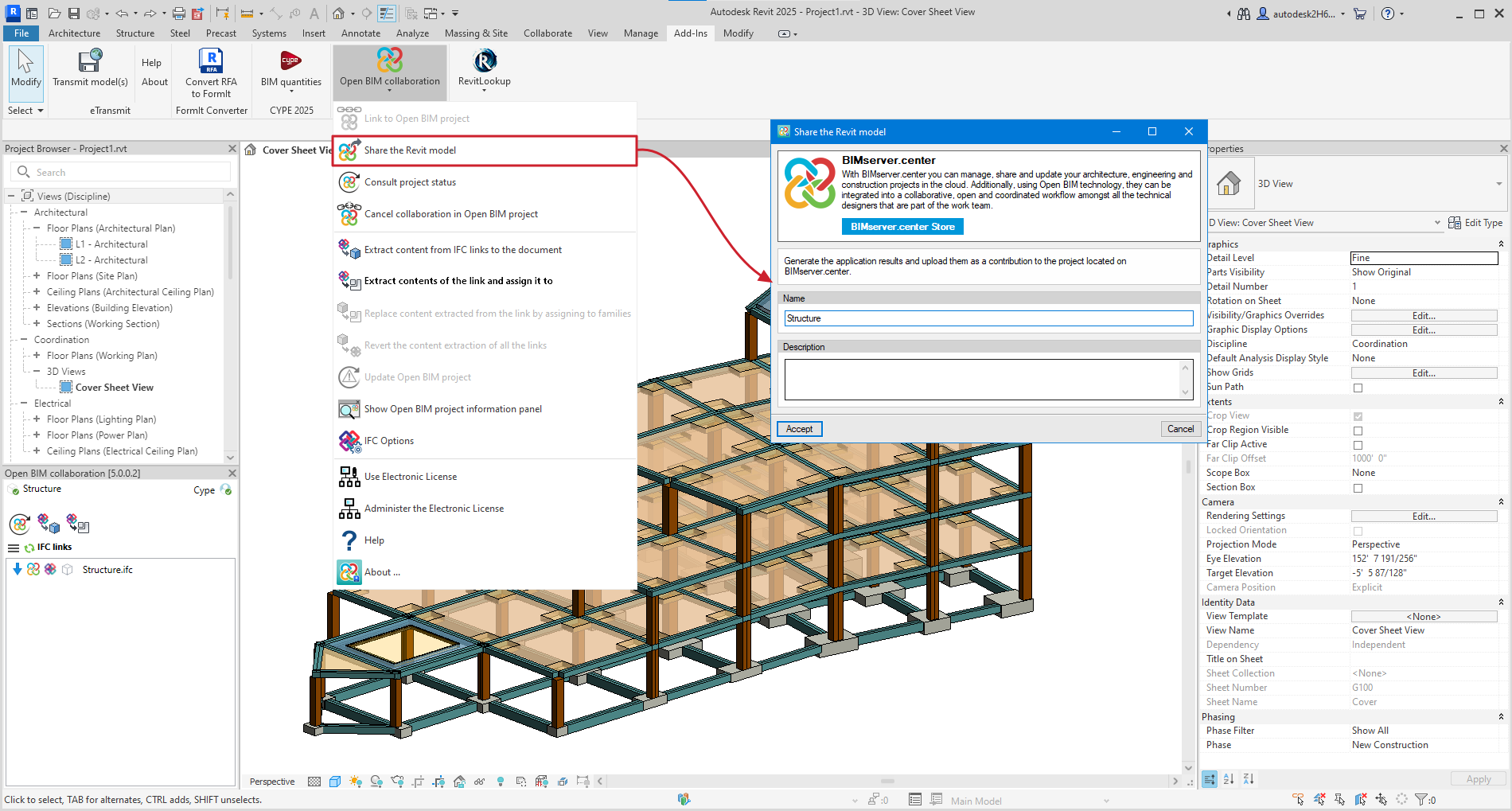
Generating native Revit® elements based on a structural IFC
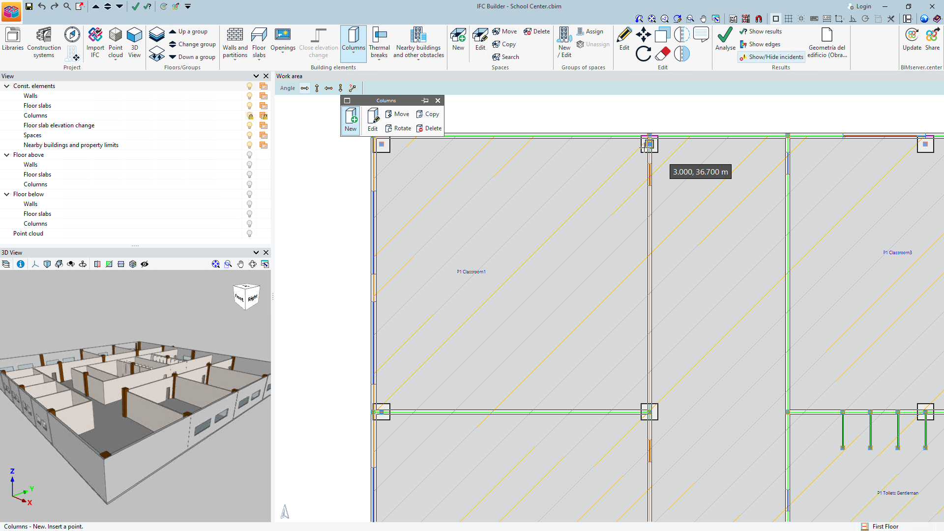
Version 2025.a of "Open BIM - Revit Plugin" includes a new module that allows users to convert a structural model (included in a project on the BIMserver.center platform) into native Revit elements by assigning families. The options of this module are centralised in the "Extract contents of the link and assign it to families" option in Revit's "Open BIM Collaboration" menu.
To use the "Generation of native Revit elements based on a structural IFC" module, users must install the "Open BIM - Revit" plugin (which can be downloaded from the BIMserver.center platform) and have the necessary permissions in a separate CYPE license, which is purchased through an annual subscription.
As well as implementing this module, version 2025.a of the "Open BIM - Revit Plugin" is compatible with Revit versions 2021 to 2025.
How to use the "Generation of native Revit elements based on a structural IFC" module
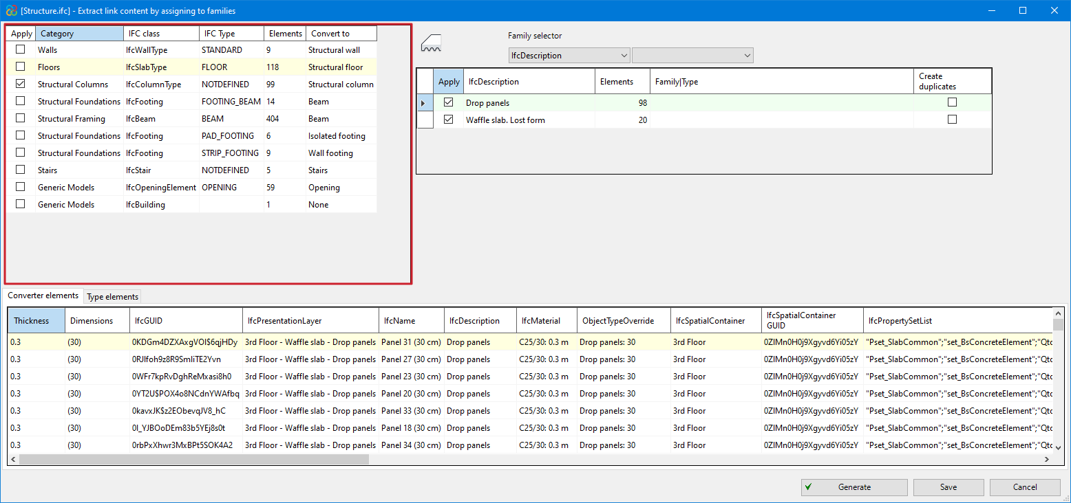
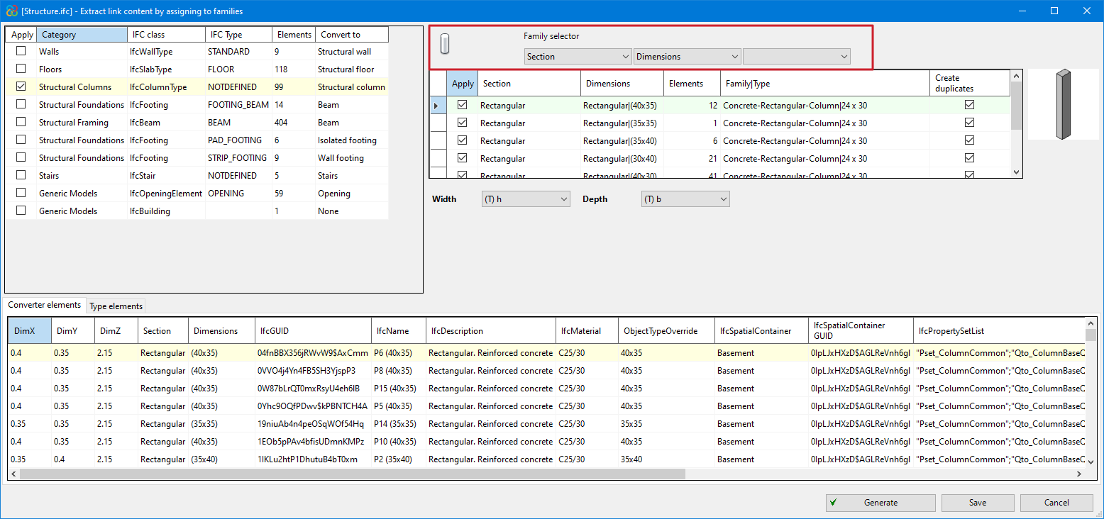
After selecting the "Extract contents of the link and assign it to families" option, a dialogue box with the same name opens, which is described in detail below:
- Main section
All the categories of structural elements detected in the IFC links of the imported model are shown in the top left corner and are grouped by the Class and Type of IFC to which they belong. The number of existing instances and the Revit native category to be converted are also displayed from these groups.
The categories that can be detected in this version (2025.a) are the following:
- Walls
- Floors
- Structural columns
- Structural framing
- Structural foundation
- Stairs
- Ramps
- Opening
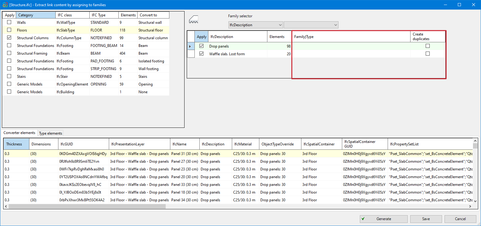
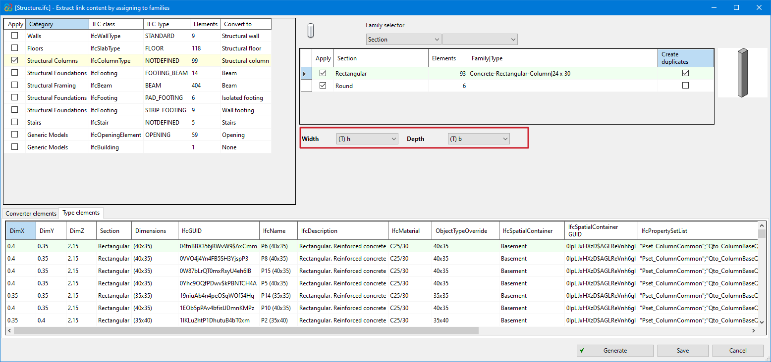
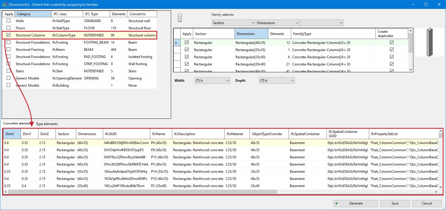
- Revit native family selector (Converter)
In the highlighted red part of the image, all types are shown together with the instances of the category that have been selected in the "Main section". The existing families in the Revit template can be assigned to them and converted to native.
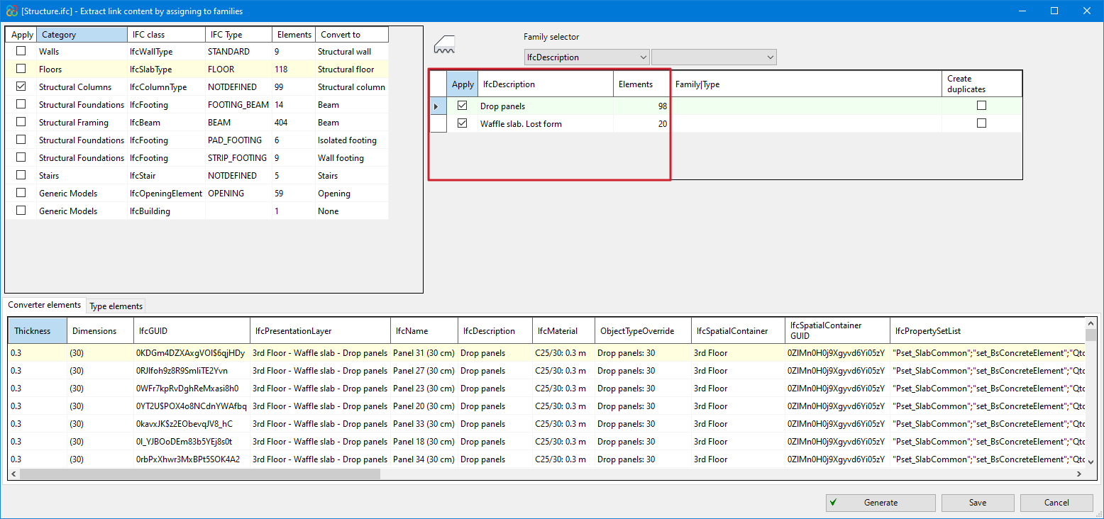
- The same table allows users to create duplicates if the assigned family contains type parameters and not instance parameters ("Create duplicates" column).
- When assigning a family with instance parameters, users must assign the parameters of the family with no need to duplicate types (users are recommended to load the families that are necessary and are not included by default in the Revit template before exporting).
- Several filtering buttons are available to make the workflow easier for the users, allowing them to view different types of instances.
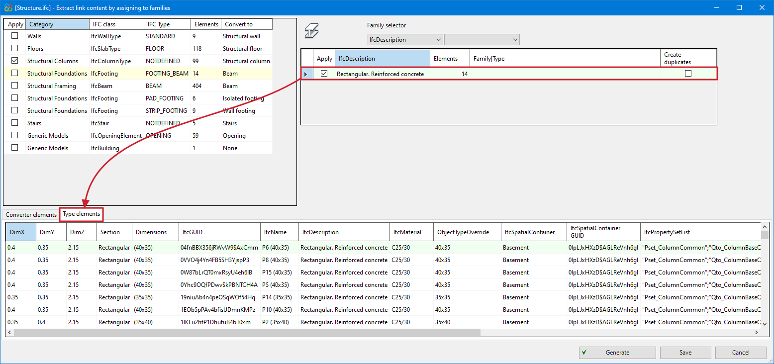
- Converter instances/Type instances
In the bottom part of the dialogue box "Extract contents of the link and assign it to families", the information for all the instances of the converter is displayed or, in the case of selecting a specific type, only the information for the instances of this type can be seen.
Improved use of data entry tables
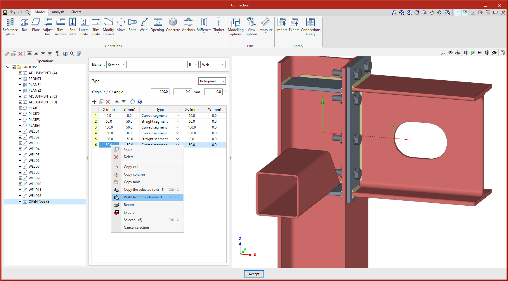
Up until version 2025.a, in order to paste information from the clipboard into the data entry tables, these tables needed to have several rows greater than or equal to that of the source table to be pasted. Therefore, only the information in the rows of the table was copied, without adding new ones.
As of version 2025.a, when pasting tables from the clipboard, if the number of rows of the source table is larger, the number of rows needed to paste the whole table will be created.
Improved operations list
Version 2025.a includes the following options and improvements to the operations tree:
Drag and drop
This feature allows users to select, move and drop operations or groups of operations to another position. With this new tool, an operation can be moved to the desired position without having to go through the intermediate positions one by one.
Icons
The operations list includes an identifying icon for each operation in the list.
Move to the top
Moves the selected operation or group to the top of the list.
Move to the end
Moves the selected operation or group to the end of the list.
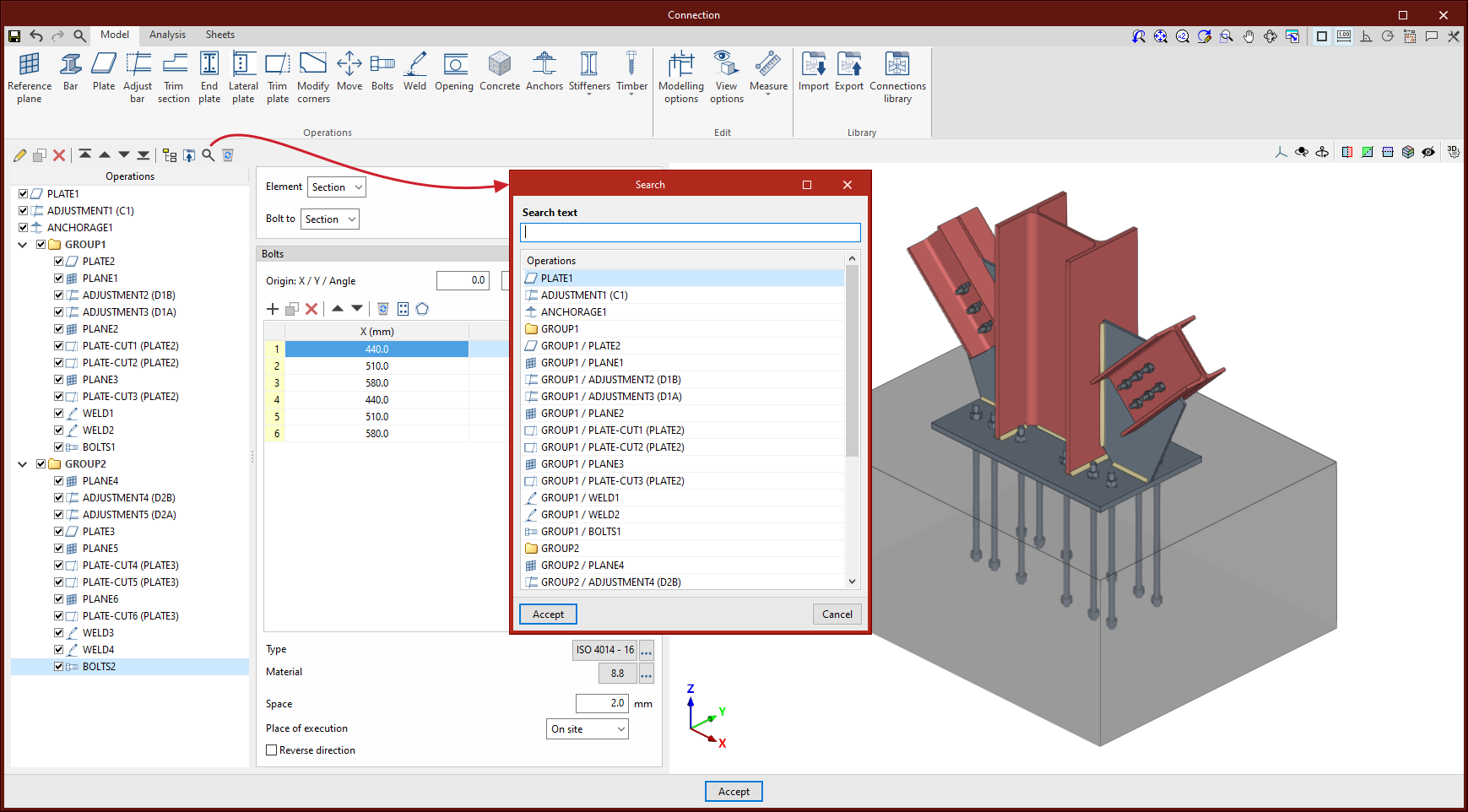
Search
Allows users to search for operations by text.
Delete all the elements in the list
Deletes all operations and groups of operations from the list.
Selecting the pressurisation systems
Now, in version 2025.a, CYPEFIRE Pressure Systems can be used to download staircase pressurisation system manufacturers' catalogues in order to select the systems and complete the design of each of the systems entered.
Once the analysis has been carried out, users can select the system that best meets their needs from the list of systems and perform a graphical check to ensure that it meets the designed requirements.

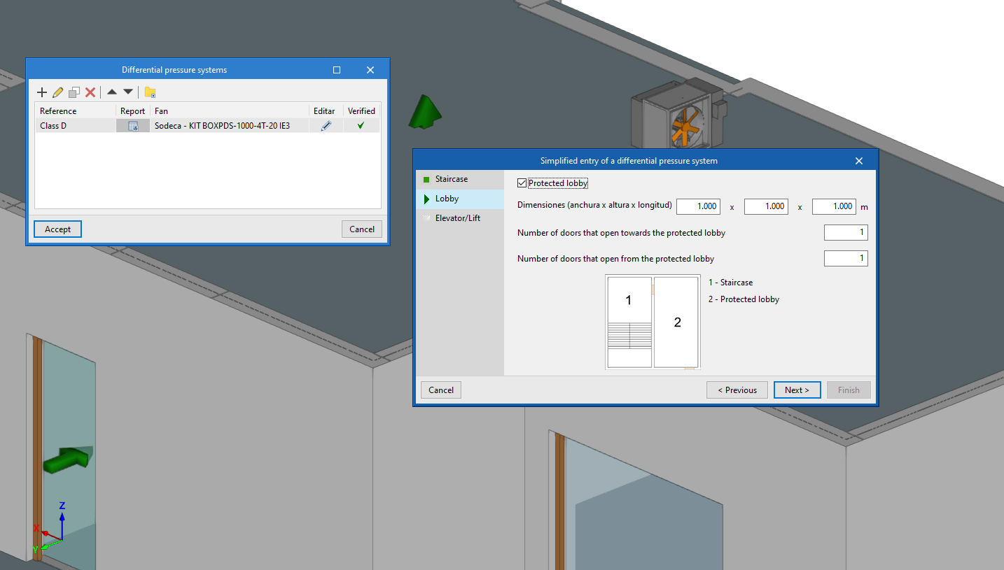
Data entry wizard
The data entry wizard is used to classify the project spaces in order to generate a staircase pressurisation system according to class and leakage.
The wizard will assist users in collecting the geometrical data of the staircase to quickly obtain all the leaks produced and to obtain the result with greater ease.
The option to enter all information manually or even to make minor modifications to the pressurisation system generated by the wizard is still available.
New 3D work environment
As of version 2025.a, the design of pressurisation systems in CYPEFIRE Pressure Systems will be carried out using a three-dimensional work environment.
Now, the leaks produced in the different building elements (doors, windows or partitions), in addition to the pressurisation system, can be included via the "3D view" or the different work planes. Each of the element types corresponds to a layer of the model, which can be activated or deactivated independently.
The program allows users to keep working on 2D templates from the BIM model or imported from the program in DXF, DWG, DWF formats; or in various image formats (JPEG, JPG, PNG or WMF). This way, working compatibility is maintained in those projects that do not have a 3D architectural model.
Jobs created with previous versions of the program can no longer be read, so it is recommended to use version 2024.f to continue working with this version.

Concrete nodes (new CYPECAD module)
CYPECAD version 2025.a includes the new "Concrete nodes" module. With this module, CYPECAD can verify the seismic design requirements to be met by the beam-column nodes of reinforced concrete frames that are part of the seismic resistance system.
More information on how this module works can be found in CYPECAD’s new feature Checking the requirements for the seismic design of reinforced concrete nodes (new CYPECAD module).
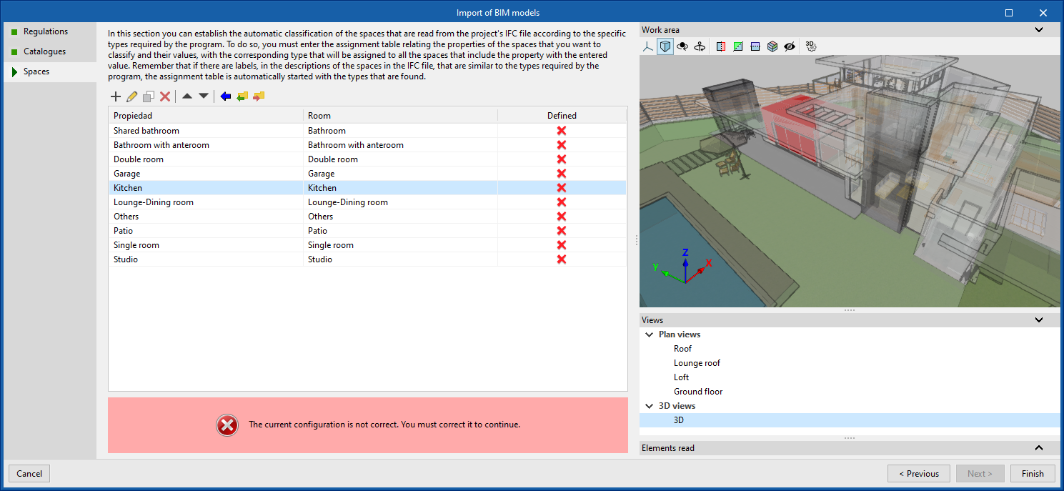
Space import assistant
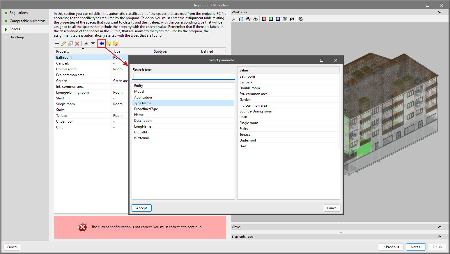
The space import assistant allows users to classify the spaces in the project's IFC file according to the specific types in each program.
If values similar to the specific types in the program are found in the space descriptions in the IFC file, the assignment table is automatically completed with the types found.
Furthermore, this assignment can be done manually through the parameters and values of the IFC. Once the values in the assignment table have been imported, a specific type from the program must be indicated for each of the values.
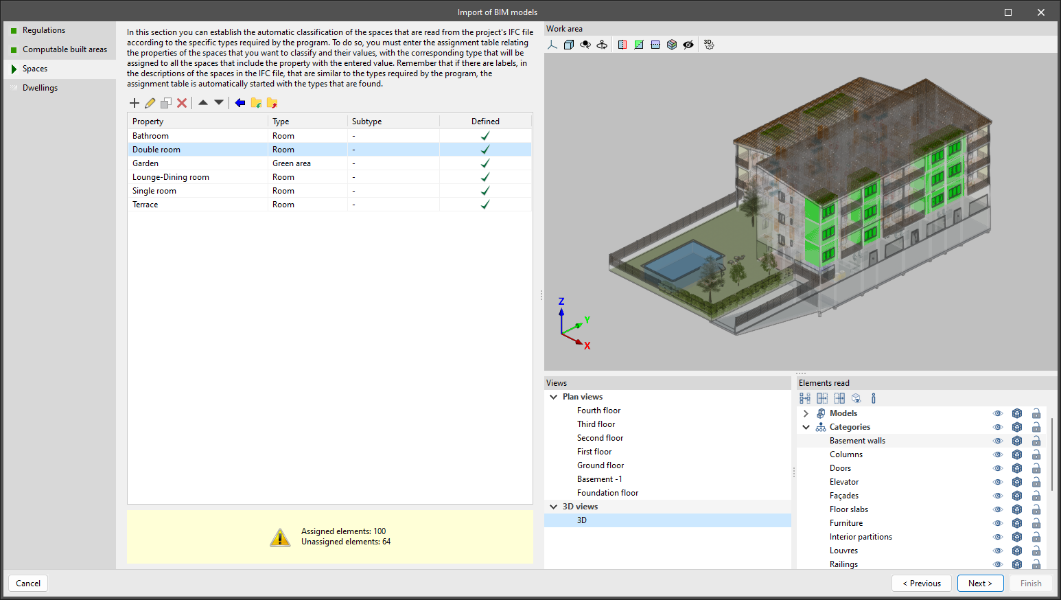
- Importing spaces via an IFC parameter
Using the blue arrow available in the toolbar, users can manually import the spaces according to the parameters available in the IFC: Name, TypeName, LongName, PSET, etc. Selecting the parameter will import all the values associated with that parameter in the mapping table.
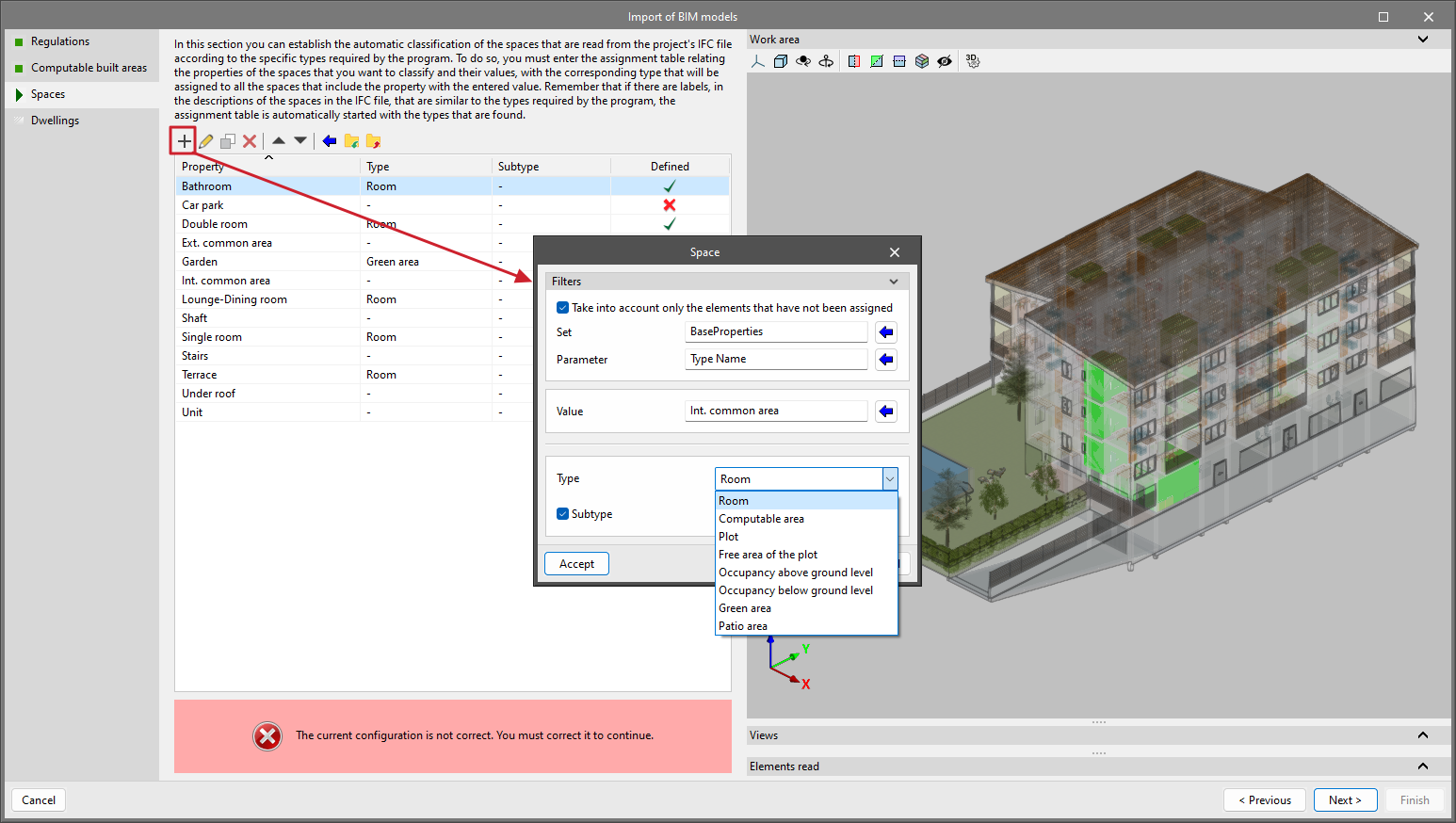
- Importing a space via an IFC value
Using the "+" button available on the toolbar, users can import a space individually. The process is similar to the one described above but in this case, instead of importing all parameter values, users can select a specific value to be imported.
Improved space import assistant and dwellings import assistant
In CYPEURBAN version 2025.a, the operation of these two assistants has been optimised:
Space import assistant
The improvements of this assistant are described in detail in this version's new feature Space import assistant.
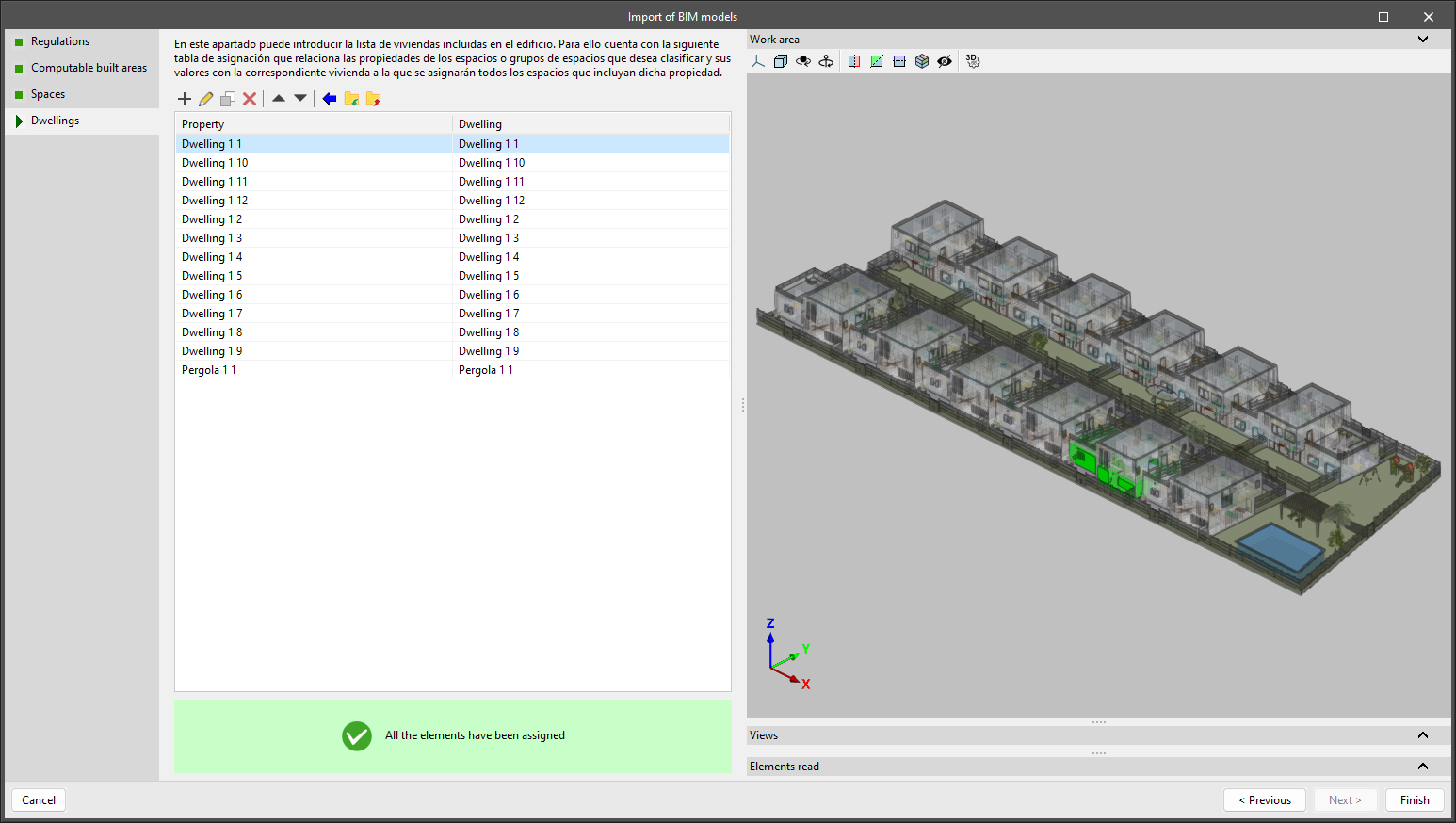
Dwellings import assistant
The dwellings import assistant allows users to import the dwellings defined in the IFC file of the project by means of spaces (IFCSpace) or groups of spaces (IFCGroup). This assignment is done manually through the parameters and values of the IFC.
Groups of operations
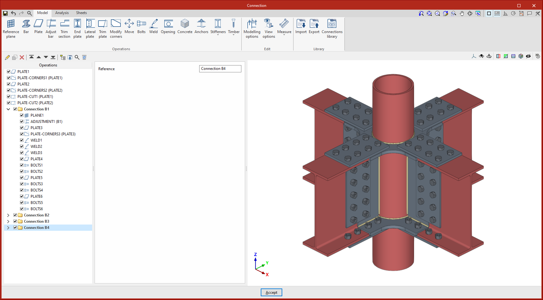
As of version 2025.a, the CYPE Connect and StruBIM Steel connection editors allow users to sort the list of operations including groups of operations.
In the operation list options bar, there is a "New group" option for adding groups. This option adds a new empty operation group.
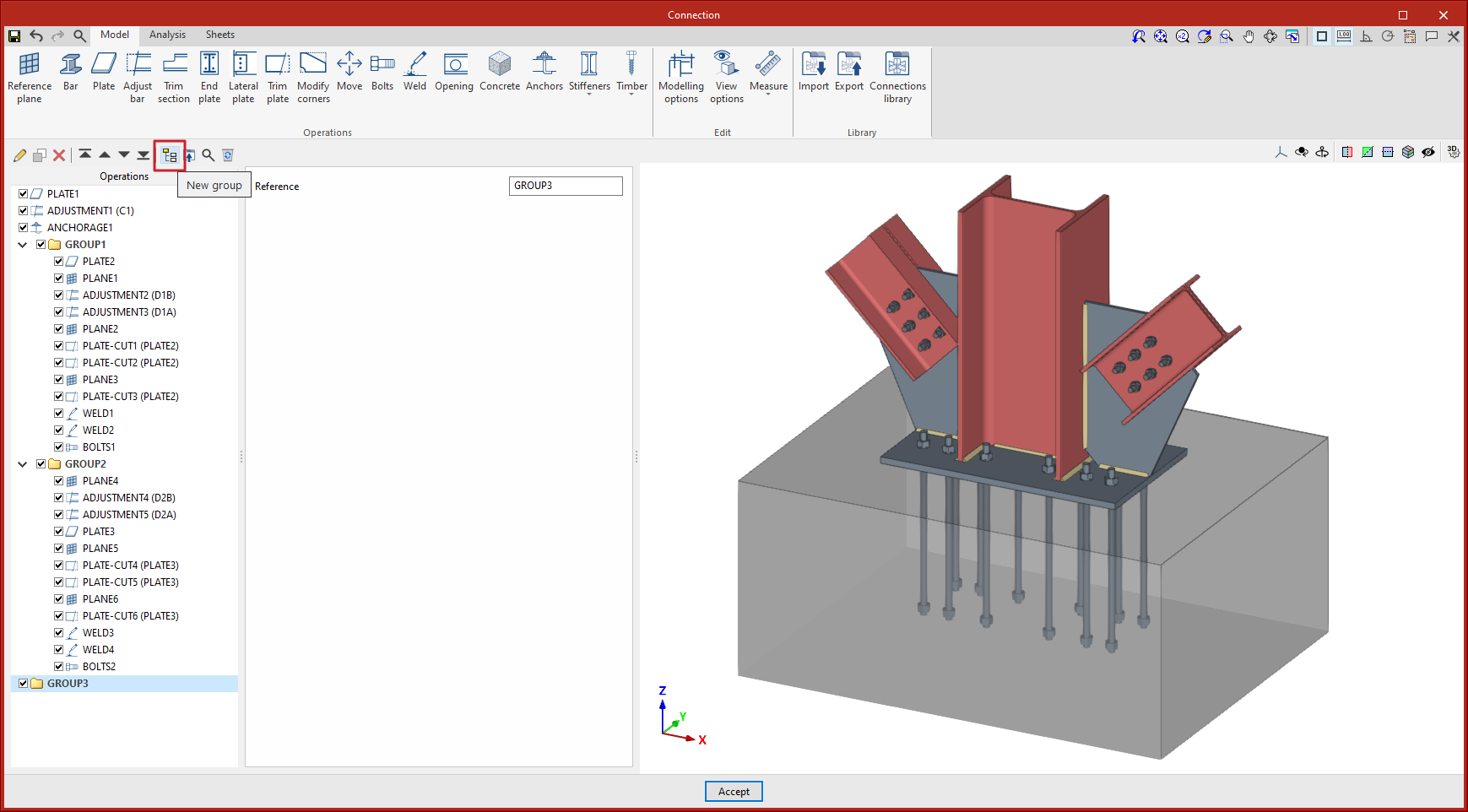
When a group is selected, new operations are added within that group.
To move an existing operation into or out of a group, the tools must be used to move it up or down, depending on the position. Operations can also be dragged and dropped into or out of a group.
Groups of operations can be collapsed or expanded, to display or hide the operations they contain.
The activate or deactivate option, located to the left of each group's name, affects all the operations it includes. A group of operations can be activated or deactivated by clicking on the option.
Pressing the "Copy" option with a group selected copies the group with all its operations.
The "Delete" option allows users to delete the group and all the operations it contains, or to delete the group and keep the operations ungrouped.
If a group is selected, the "Export selected operations to the library" option exports all the operations contained in that group.
Improved use of types
In this new version of the CYPE Architecture program, important improvements have been included regarding the types that affect all the program's building elements:
- All the elements in the job must belong to a type
In this new version, no new elements can be created without a type. To create any new element, users must create a type for this element from the types panel of the "Architecture" tab.
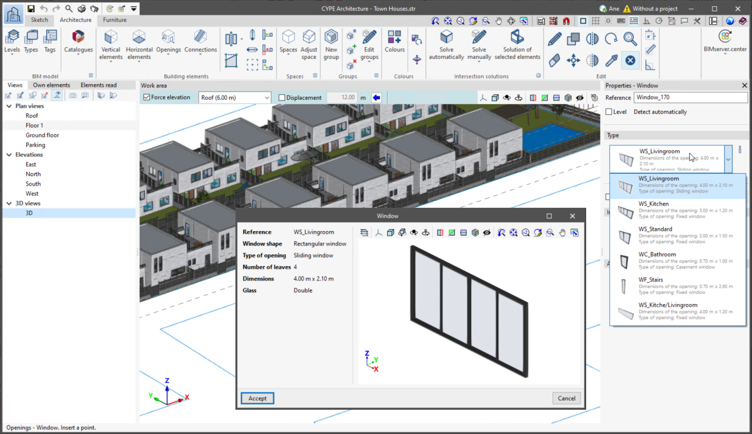
This improvement aims to ensure consistent communication with the other programs in the BIMserver.center Open BIM workflow, most of which use the building types as a base for development and analysis. - Type selection via a drop-down menu
Type selection is carried out via a new drop-down menu that provides the information needed to identify the type simply. In the drop-down menu, the basic information of the type can be found, including the name of the type, an image with the colour/texture, and extra data that help identify the type. - Copy type
The type creation and editing panel now has a "Copy " tool, allowing users to create a type from an existing type. - Automatically creating types for previous versions of jobs
If necessary, the program will automatically create types for all those elements that are not associated with a type or for those elements that have been assigned a type that does not correspond to the description of the element.
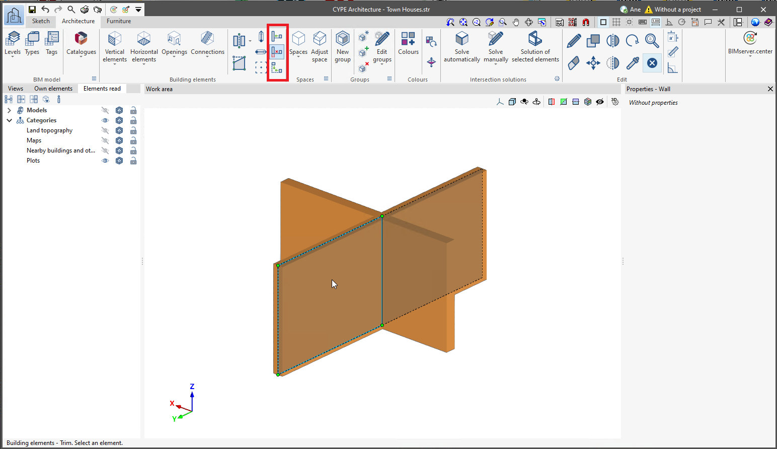
New tools: Extend, Trim and Fillet
CYPE Architecture's new tools in version 2025.a, "Extend", "Trim" and "Fillet" are available in the "Architecture" tab of the "Building elements" section.
These tools can be used with "Vertical elements": walls, curtain walls, lattices and railings.
- Extend
To extend elements, first select the element to which the others are to be extended, then select all the elements to be extended.
Once all the elements have been selected, click the right mouse button to complete the action. - Trim
To trim elements, first select the trimming element, then select the element to be trimmed, and then select the part of this element to be kept. This process can be repeated successively for all elements that intersect with the selected trimming element. - Fillet
The two elements that users want to fillet are selected and the fillet will be defined automatically.
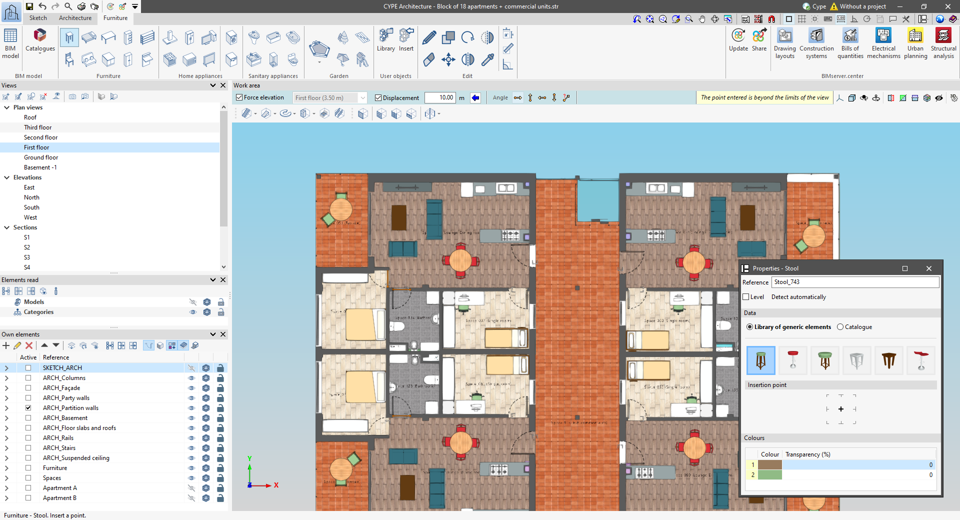
Improved options bar for entering elements in the work area
The following changes have been made to the options bar for entering elements in the work area:
- New “Force elevation” feature
The "2D Mode" and "3D Mode" options have been replaced by the "Force elevation" option. When the "Force dimension" option is activated, when snapping a model component, its position will be projected onto the work plane, where the new element will be inserted.
Alternatively, when snapping a model component, the new element will be inserted at the exact position of that component, even if it is outside the working plane. - Viewing limits warning
If, when entering an element in a model view, it lies beyond the visible range, a warning is now displayed in the options bar. This warning, "The point entered is beyond the limits of the view", alerts users about the position of the element beyond the visible area on the screen, allowing for a quick and accurate correction.
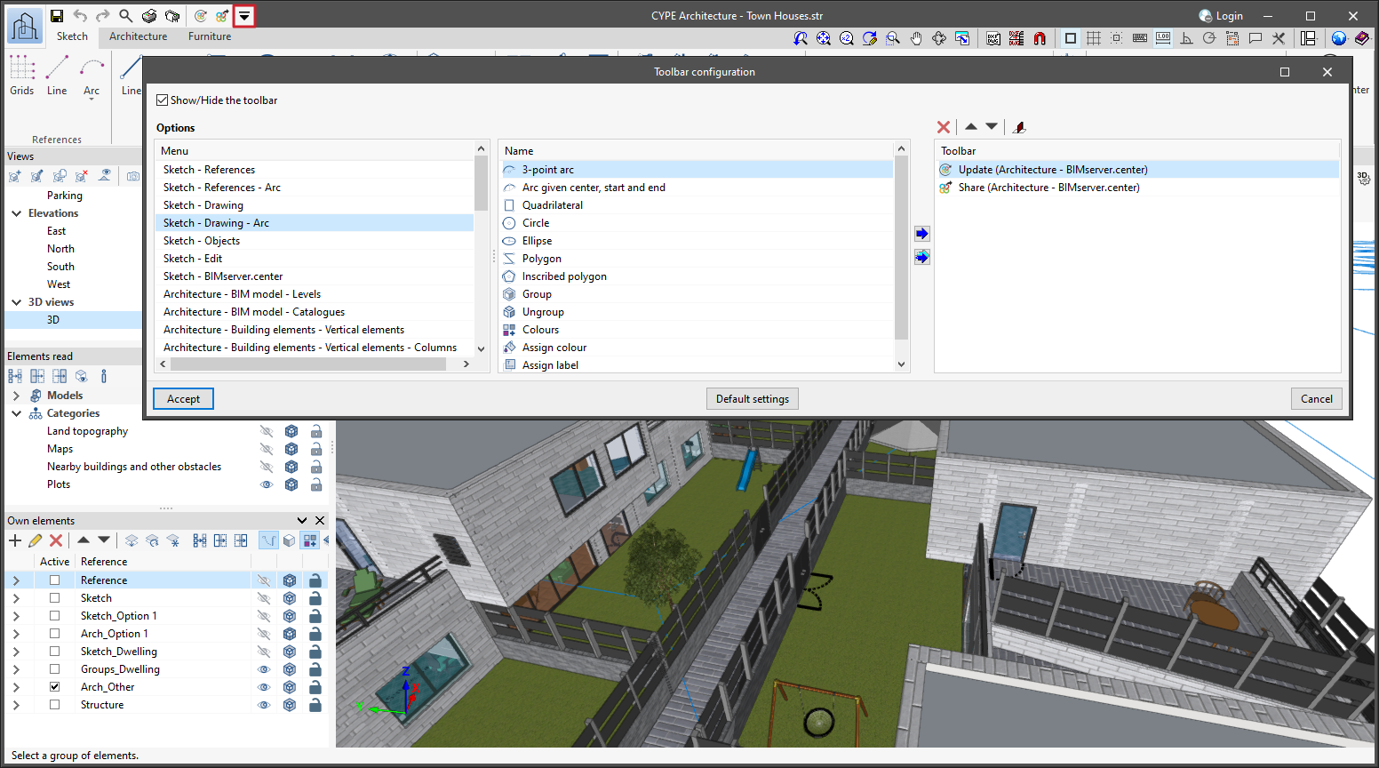
Quick access toolbar
As of version 2025.a, CYPE applications with a "Ribbon" have a customisable quick access toolbar (QAT), located in the top left corner of the program. This bar contains a set of commands that are separate from the active ribbon tab.
To add or remove a command from the quick access toolbar, a button has been included to access the configuration of the toolbar. Clicking it displays a window where users can add commands from the application's menus. Specific commands can be selected or all the commands found in a menu can be added using the "Assign all" button.
The list of commands added to the quick access toolbar provides options to perform the following actions:
- Move up (move to the left) or move down (move to the right) commands in the toolbar.
- Add a dividing line to the right of the button.
- Remove a command or dividing line from the toolbar.
Each application can include several commands in the initial settings of the quick access toolbar and can be restored using the "Default settings" option. Furthermore, applications that are connected to the BIMserver.center platform include the "Update" and "Share" options in their default settings.
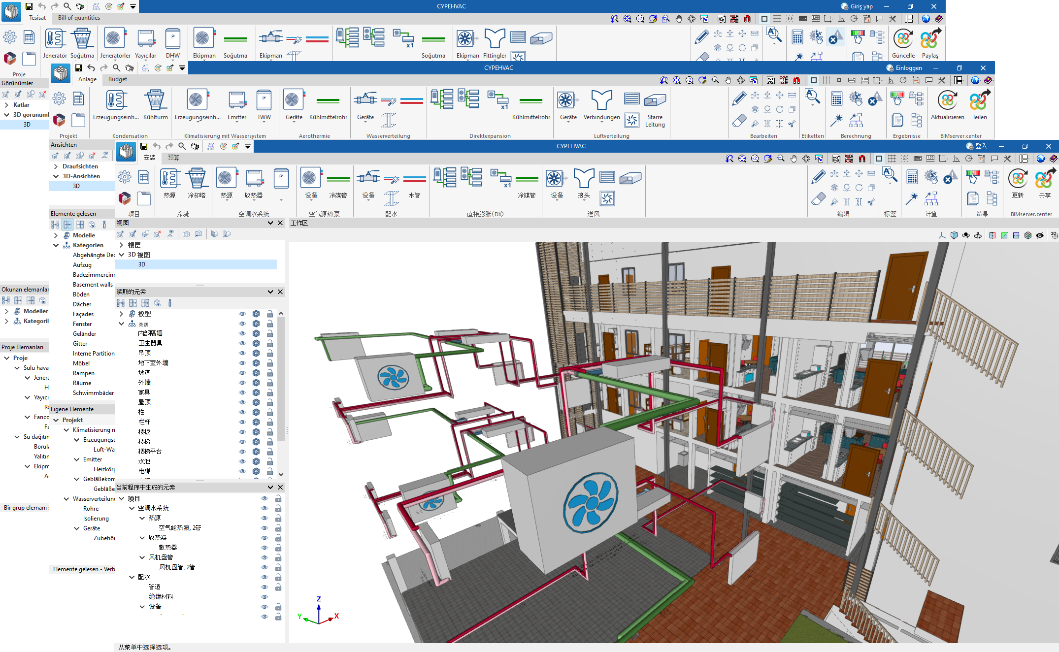
Installation in Chinese, German and Turkish
As of version 2025.a, CYPEHVAC can also be installed in Chinese, German and Turkish. This application can now be installed in the following languages:
- Catalan
- Chinese
- English
- French
- German
- Italian
- Polish
- Portuguese
- Romanian
- Russian
- Spanish
- Turkish
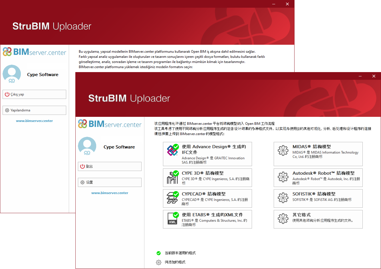
Installation in Chinese and Turkish
As of version 2025.a, StruBIM Uploader can also be installed in Chinese and Turkish. This application can now be installed in the following languages:
- Catalan
- Chinese
- English
- French
- German
- Italian
- Japanese
- Polish
- Portuguese
- Romanian
- Russian
- Spanish
- Turkish
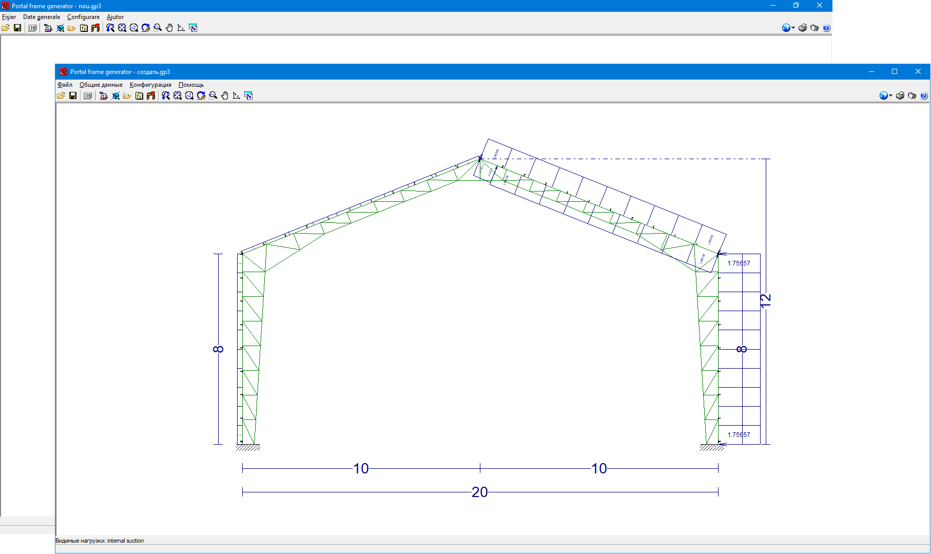
Installation in Russian and Romanian
As of version 2025.a, Portal frame generator can also be installed in Russian and Romanian. This application can now be installed in the following languages:
- Bulgarian
- Catalan
- English
- French
- Italian
- Polish
- Portuguese
- Romanian
- Russian
- Spanish
Installation in Romanian
As of version 2025.a, CYPE 3D can also be installed in Romanian. This application can now be installed in the following languages:
- Bulgarian
- Catalan
- English
- French
- Italian
- Polish
- Portuguese
- Romanian
- Russian
- Spanish
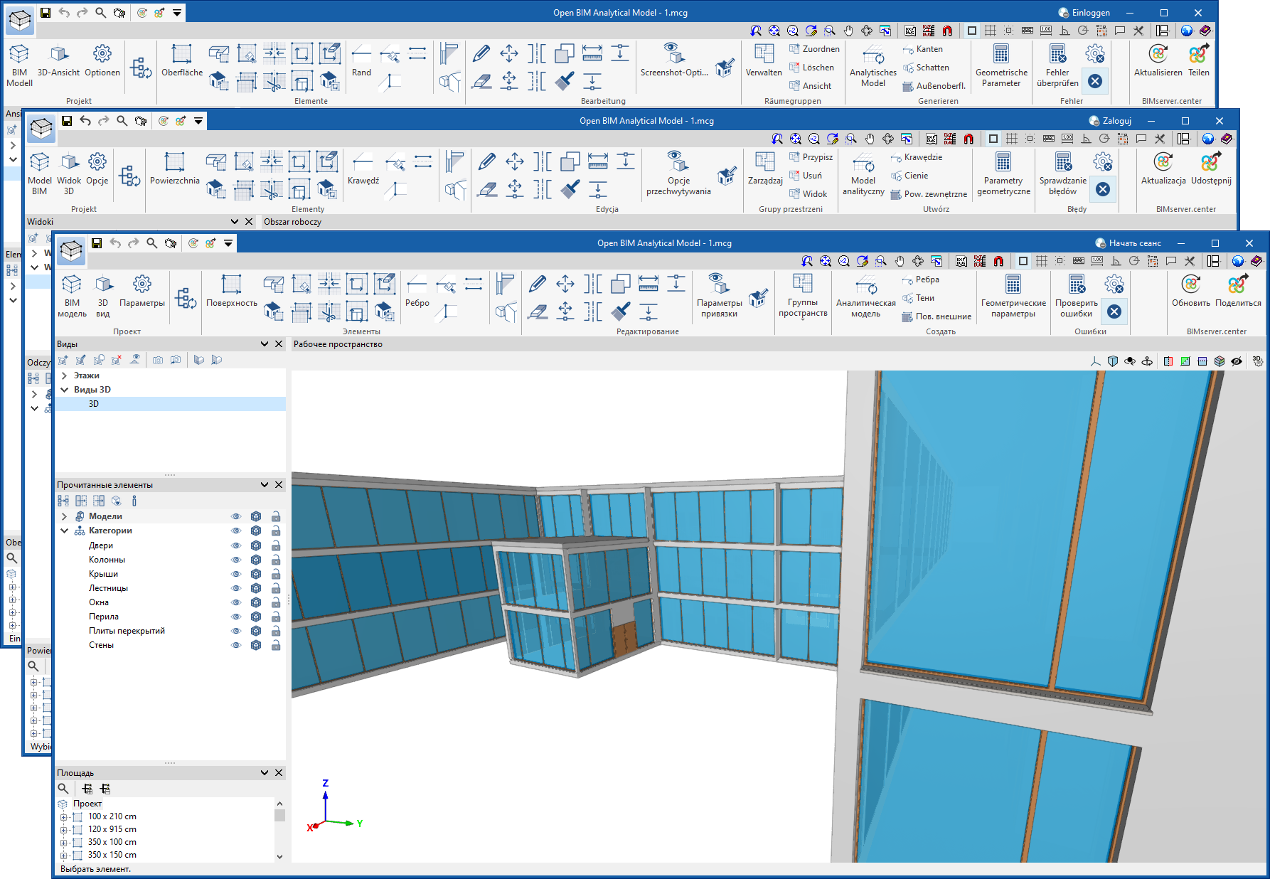
Installation in German, Polish and Russian
As of version 2025.a, Open BIM Analytical Model can also be installed in German, Polish and Russian. This application can now be installed in the following languages:
- Chinese
- English
- French
- German
- Italian
- Japanese
- Polish
- Portuguese
- Romanian
- Russian
- Spanish
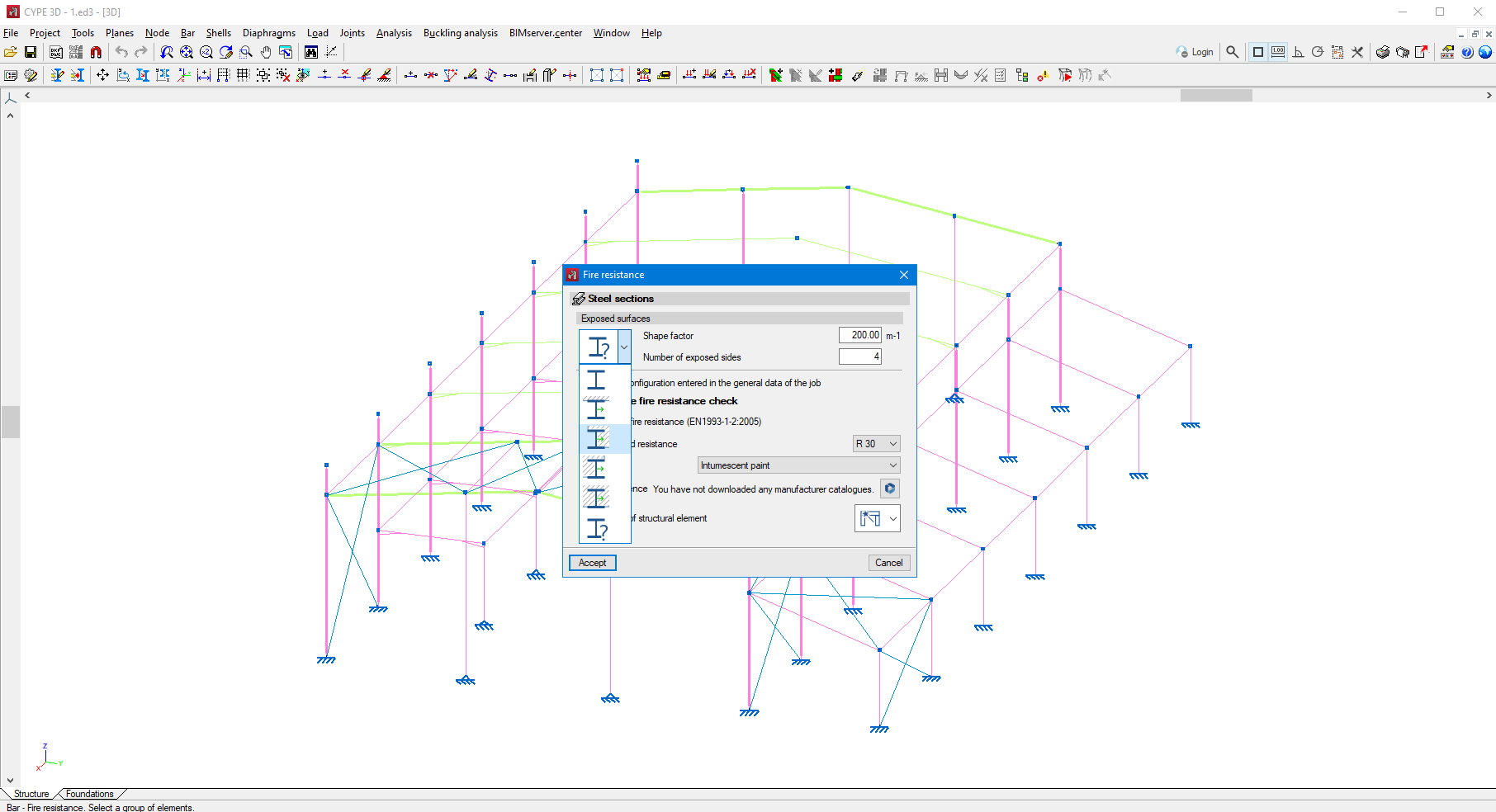
Selecting intumescent paints by manufacturer
In version 2025.a, intumescent paints from manufacturers' catalogues have been incorporated.
Under "General data > Fire resistance", when selecting "Check fire resistance" for steel sections, the type of protective coating can also be selected.
By selecting "Intumescent paint" the available catalogues can be used.
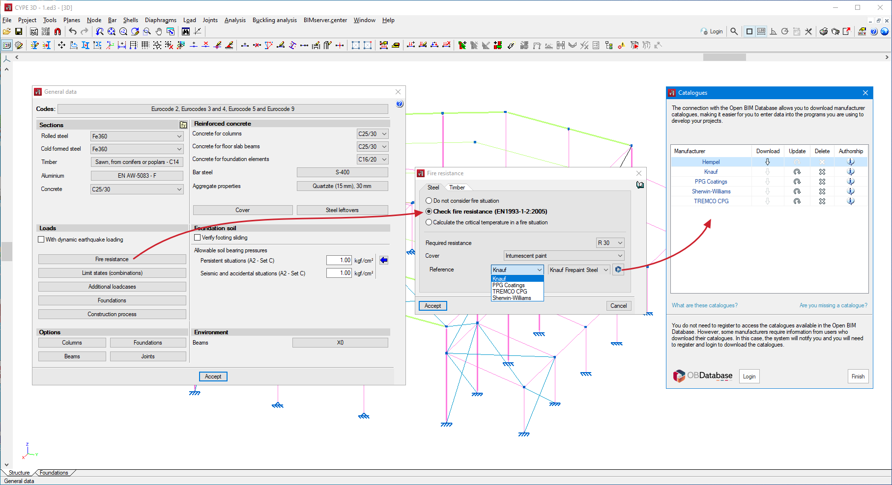
The thickness of intumescent paint required for the protection of each bar is obtained from the selected catalogue, based on the estimated critical temperature, the shape factor, the number of exposed sides and the type of structural element (column or beam).
From the "Bar" menu, under "Fire resistance" it is possible to assign the type of structural element, either a column or a beam, to each bar. By default, the program assigns the first option, which automatically determines whether it is a column or a beam, depending on the angle formed by the bar with the horizontal plane.
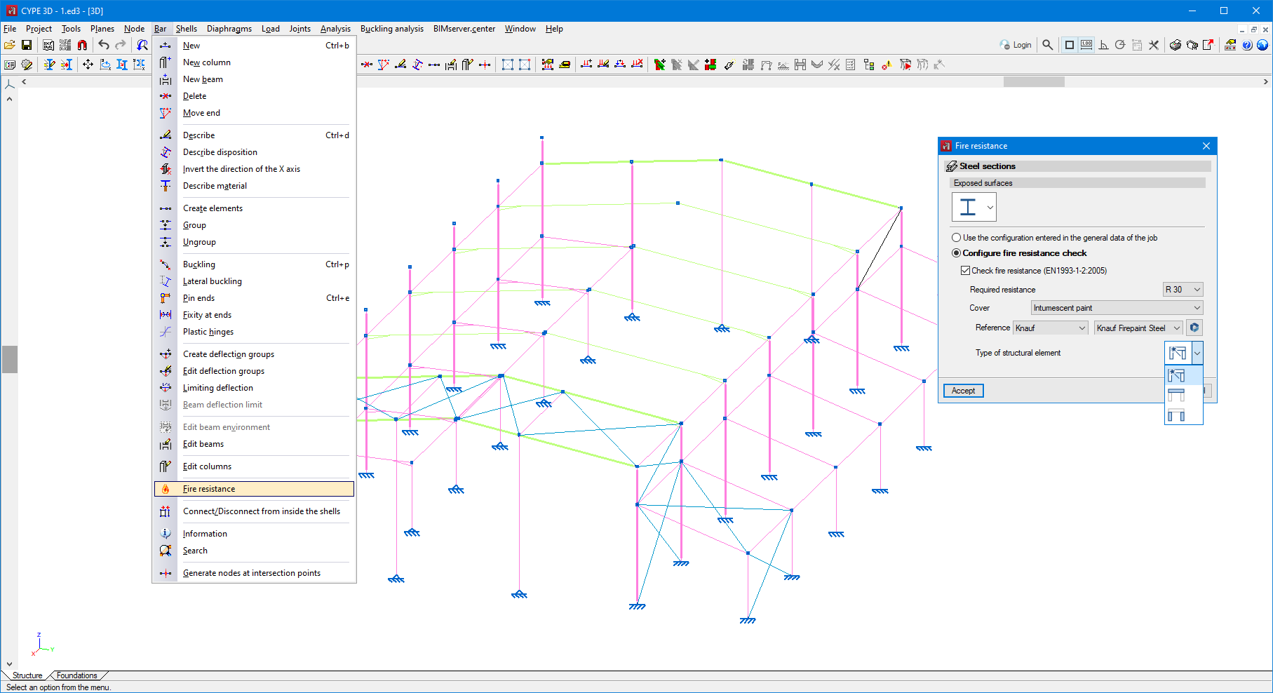
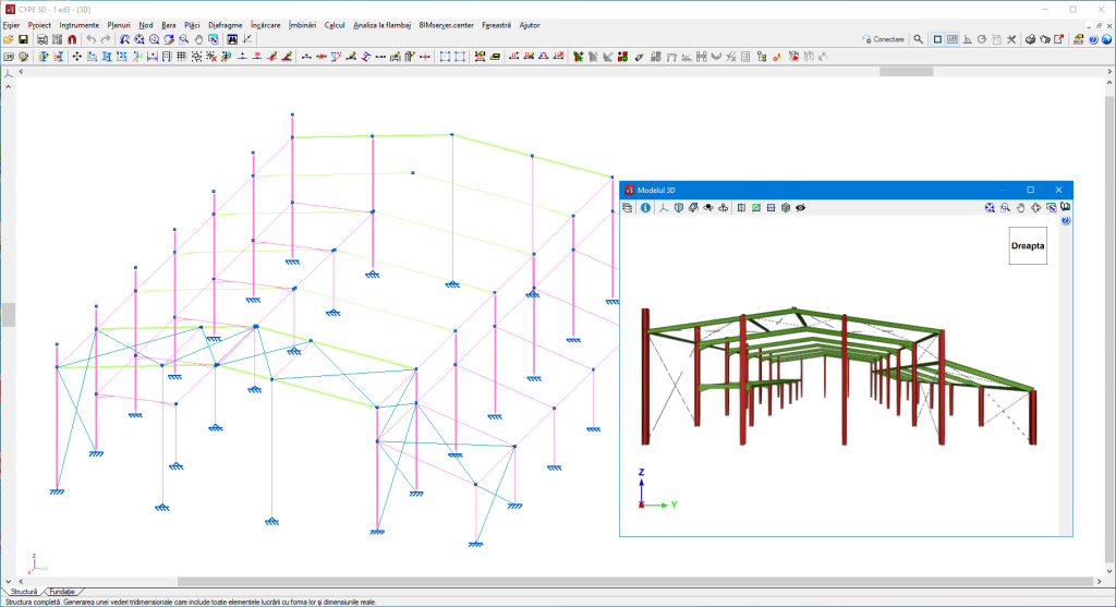
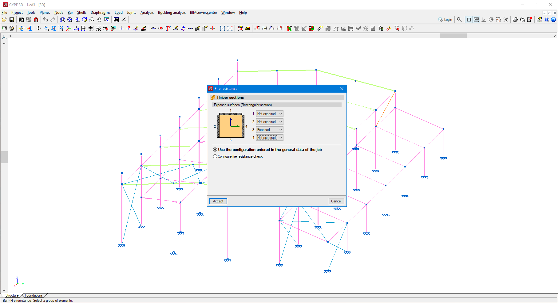
Selecting surfaces exposed to fire in steel sections and timber bars
In CYPE 3D version 2025.a, we have implemented the selection, by bar, of the surfaces exposed to fire, in steel sections and timber bars.
In the "Bar" menu, the "Fire resistance" option can be used to assign the exposed surfaces to the selected bars. This option will be active when users have selected the "Check fire resistance" option in "General data".
For steel sections, users can choose any of the predefined options from the drop-down button, in which the program automatically determines the form factor based on the exposed surfaces; or select the last option, where they manually enter the form factor and the number of exposed surfaces.
For rectangular section timber bars, users may decide whether or not each of the four surfaces of the section is exposed to fire.
Up until version 2025.a, the program would conservatively consider all exposed faces.
With this new feature, users will be able to optimise the thickness of the protective coatings as well as the sections of the bars when the faces of the bars are not exposed to fire.
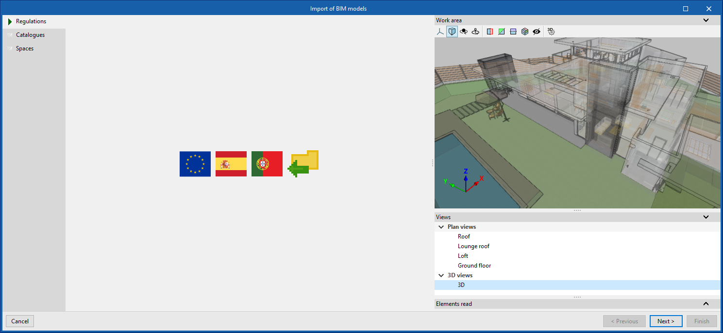
Improvement in the new job creation assistant
The following sections have been included in the new job creation assistant:
- Regulations
Selecting the regulations to be applied.
- Catalogues
Selecting the manufacturer's catalogues.
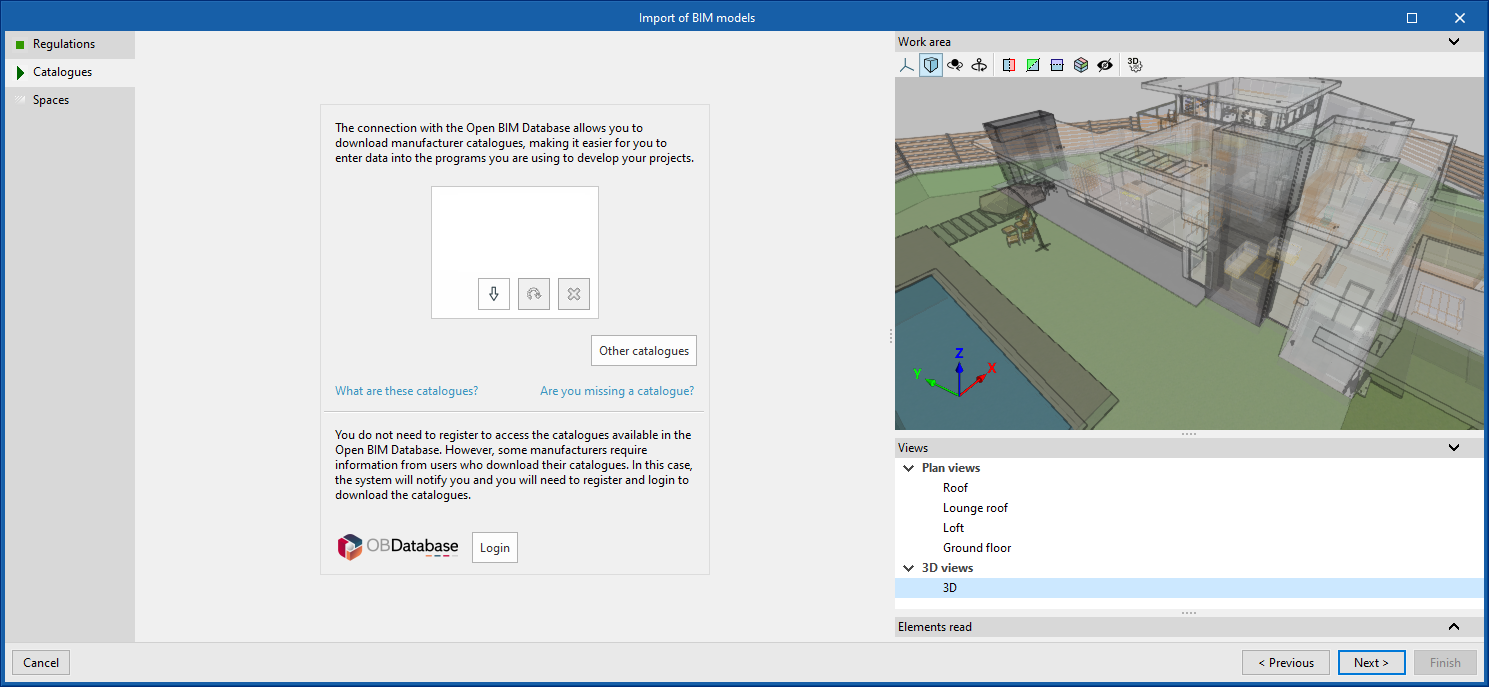
- Spaces
Configuring spaces if the BIM project contains them.
Generating native Revit® elements from a structural IFC (new module from the Open BIM - Revit Plugin)
Version 2025.a of the "Open BIM - Revit Plugin" includes a new module that allows users to convert a structural model (included in a project on the BIMserver.center platform) into native Revit elements by assigning families. The options of this module are centralised in the "Extract contents of the link and assign it to families" option in Revit's "Open BIM collaboration" menu.
To use the "Generation of native Revit elements based on a structural IFC" module, users must install the "Open BIM - Revit" plugin (which can be downloaded from the BIMserver.center platform) and have the necessary permissions in a separate CYPE license, which is purchased through an annual subscription.
As well as implementing this module, version 2025.a of the "Open BIM - Revit Plugin" is compatible with Revit versions 2021 to 2025.
More information about this new module can be found in the new feature "Generating native Revit elements based on a structural IFC".
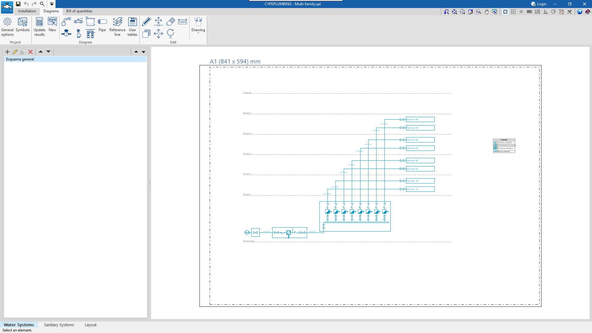
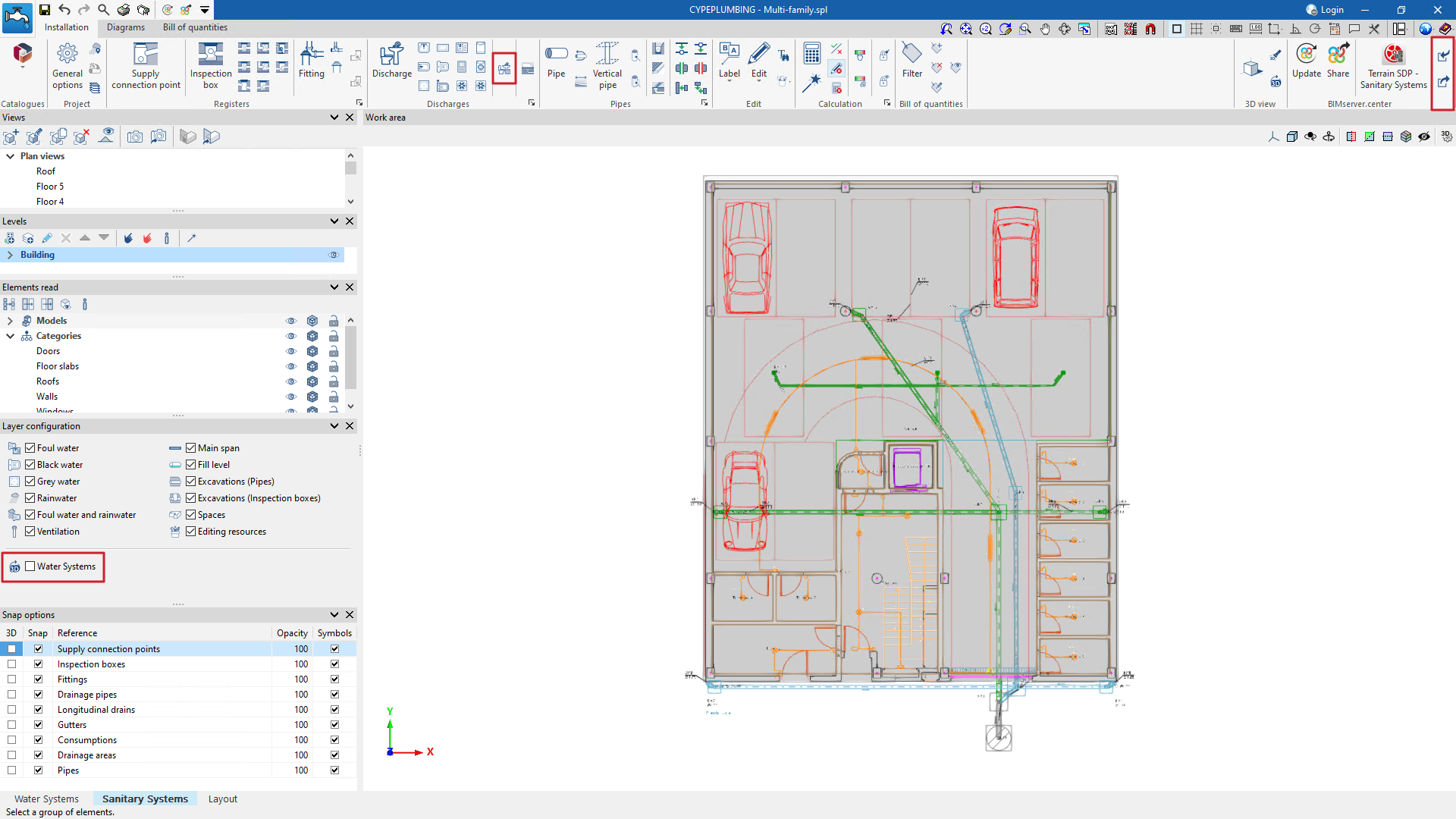
CYPEPLUMBING (new program)
CYPEPLUMBING combines the features of CYPEPLUMBING Water Systems, CYPEPLUMBING Sanitary Systems and Open BIM Layout. These combined applications are organised in three tabs at the bottom of the CYPEPLUMBING main window: "Water Systems", "Sanitary Systems" and "Layout". Consequently, the CYPEPLUMBING Water Systems and CYPEPLUMBING Sanitary Systems applications have been discontinued and will no longer be available in version 2025.a. However, older versions of these two programs can be downloaded from the BIMserver.center platform "Store". The Open BIM Layout application will continue to be developed in version 2025.a, as it still centralises the creation of drawings for many other applications.
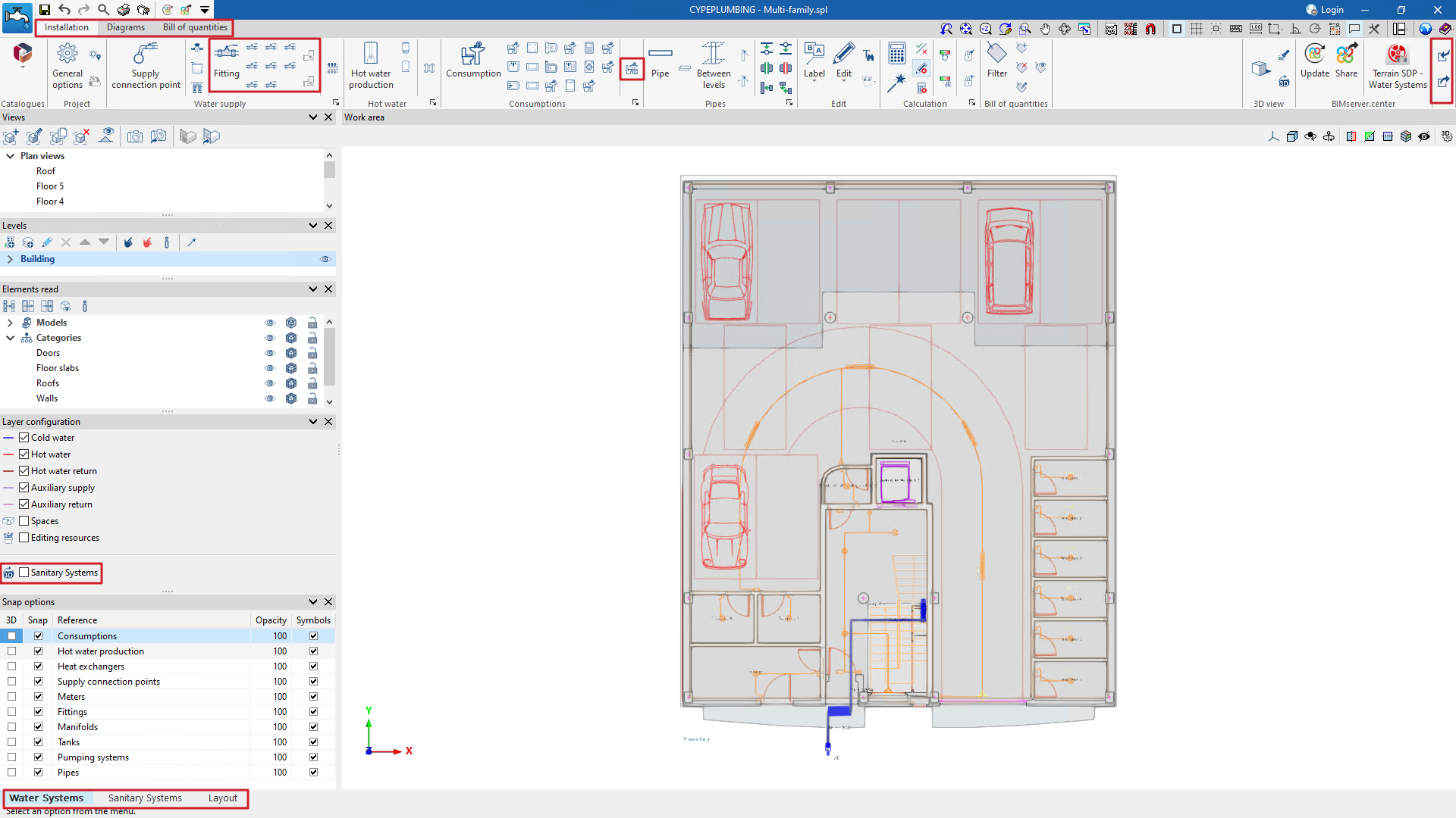
- Water Systems and Sanitary Systems tabs
These tabs include the tools that allow users to enter and design water supply and wastewater and rainwater drainage systems, respectively. They are an improvement on the tools that were available in CYPEPLUMBING Water Systems and CYPEPLUMBING Sanitary Systems.
Each of these two tabs is organised into three other tabs located at the top of the main window (Installation, Diagrams and Bills of quantities). These three tabs were already available in CYPEPLUMBING Sanitary Systems. CYPEPLUMBING Water Systems did not have a "Diagrams" tab, so users had to use the CYPEPLUMBING Schematic diagrams program to generate the diagrams of a water supply system. CYPEPLUMBING no longer needs to connect to another application to generate these diagrams.
Entering an element with associated consumption and discharge in either of the two tabs means that the discharge (Sanitary Systems) or consumption (Water Systems) is automatically included in the other tab. In previous versions, the Open BIM Water Equipment program (now discontinued in version 2025.a) was required for the discharge associated with these elements to be entered in CYPEPLUMBING Sanitary Systems and the consumption in CYPEPLUMBING Water Systems (using the Open BIM workflow).
- Layout tab
In this tab, users can create drawings composed of the two systems (water supply and water drainage) including the graphic information imported from other applications. Specific water supply and drainage tags (not available in the Open BIM Layout application) can also be assigned and placed together with the tags that users can create in a 3D view of the drawing.
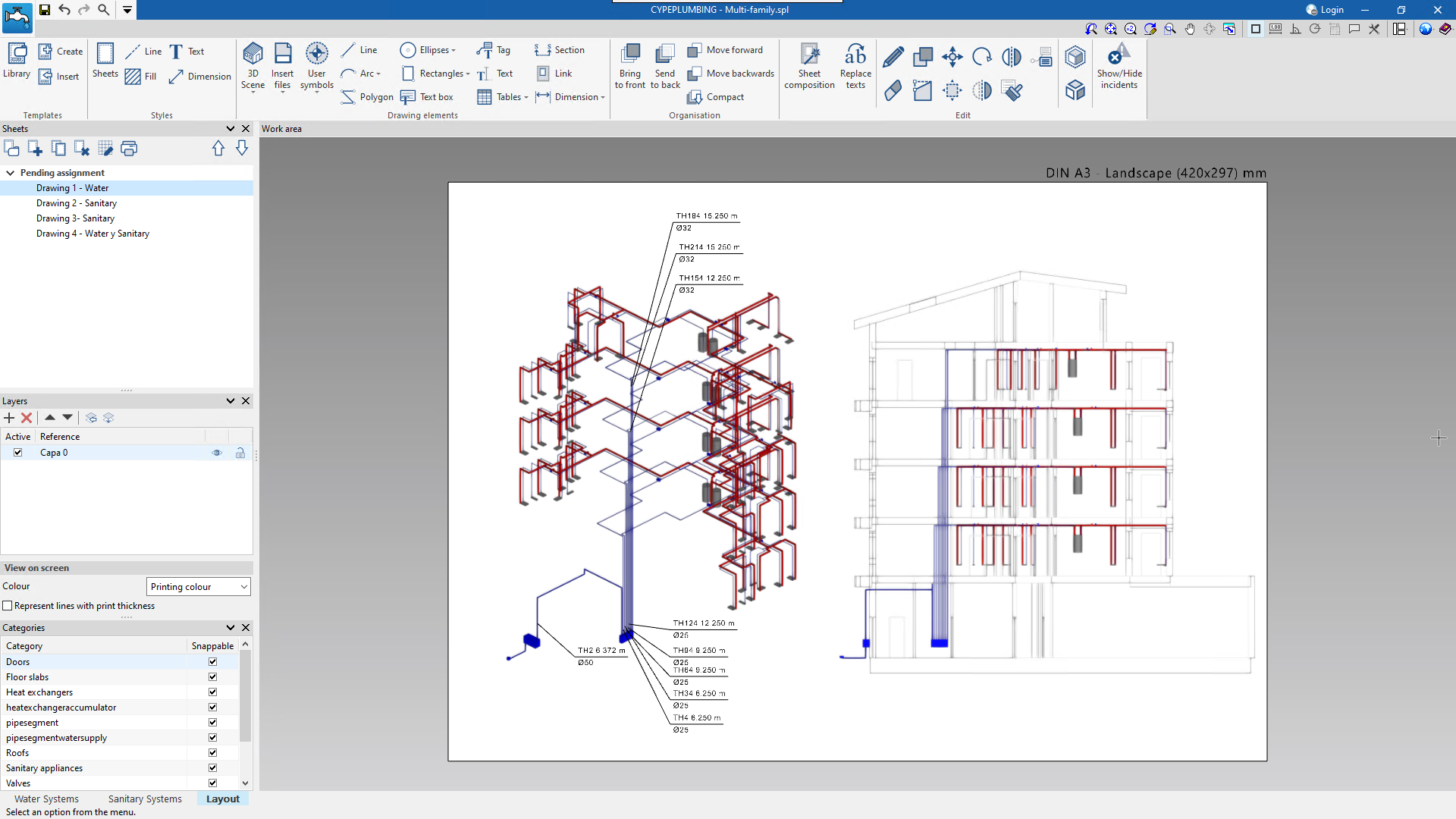
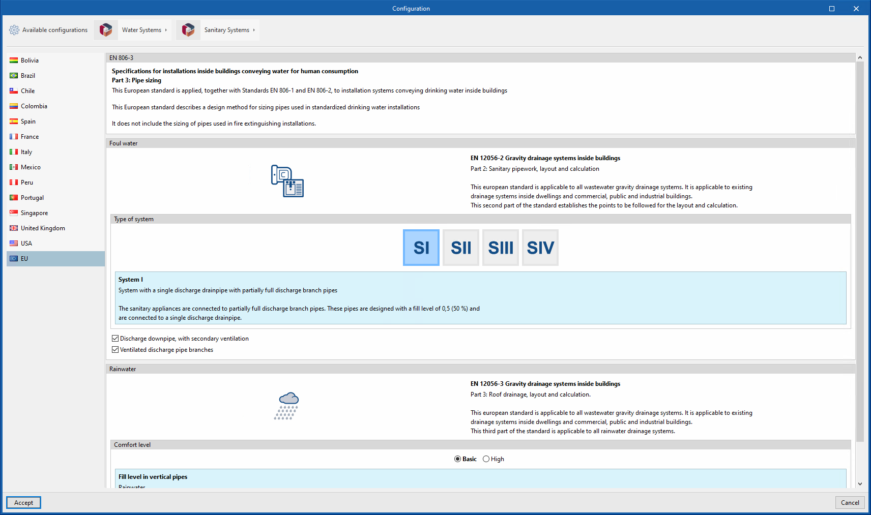
Another CYPEPLUMBING improvement is the country selection when creating a job so that the application is automatically configured with the corresponding water supply and drainage standards.
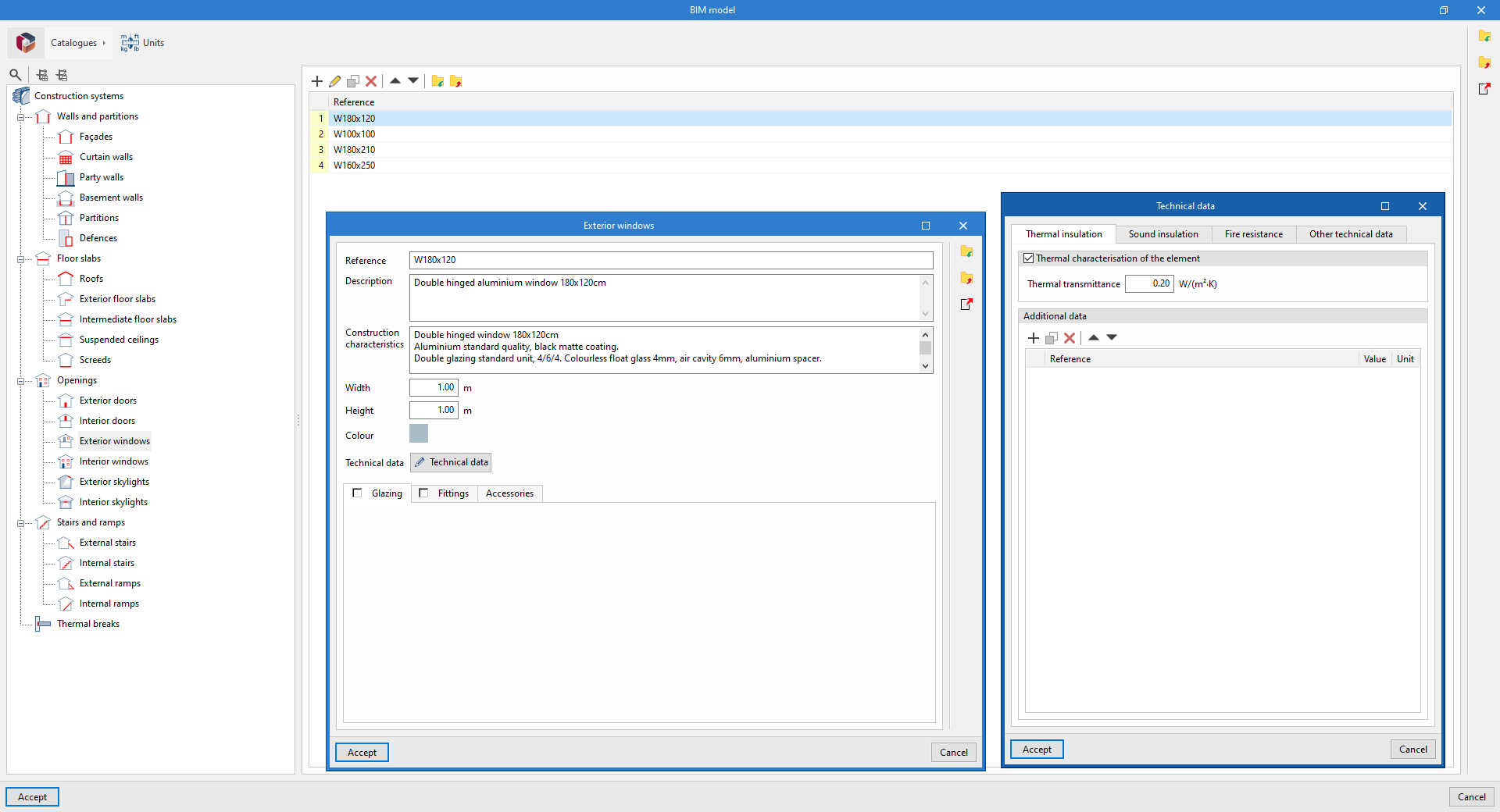
Overall technical data for "Thermal insulation" in windows and skylights
As of version 2025.a, an overall "Thermal transmittance" value can now be defined for windows and skylights as an alternative to the "Glazing" and "Fittings", which has been the case up to now. For this purpose, the "Thermal characterisation of the element" option has been added to the "Thermal insulation" tab of the window "Technical data" in the following construction system categories:
- External windows
- Interior windows
- Exterior skylights
- Interior skylights
Thermal simulation applications can read and incorporate these properties of the contributions from IFC Builder and CYPE Construction Systems into their design models.
Furthermore, applications with a "3D Model" tab (CYPEFIRE FDS and CYPETHERM LOADS) can obtain data directly from the construction systems defined in the geometric model.
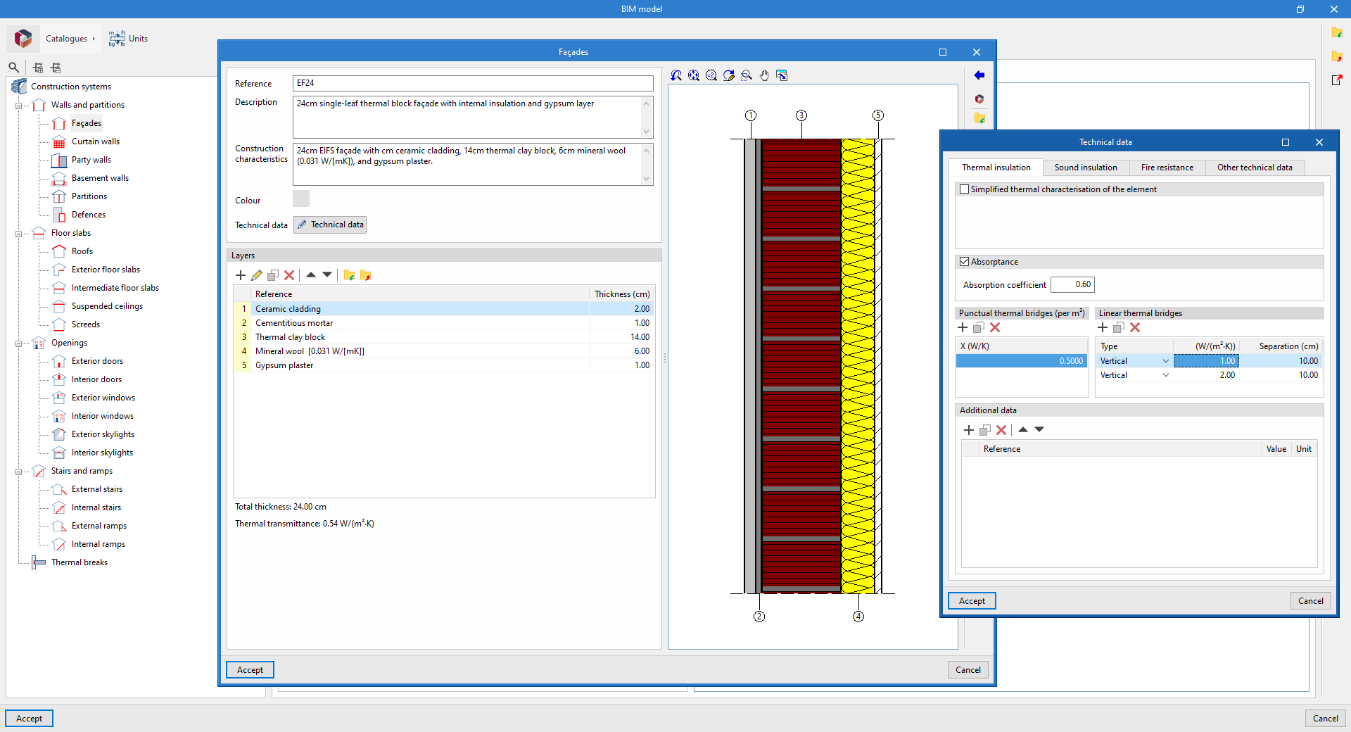
Punctual thermal bridges and linear thermal bridges
As of version 2025.a, it is possible to enter "Punctual thermal bridges (per m²)" and "Linear thermal bridges" in the "Thermal insulation" tab of the "Technical data" window for the following categories of construction systems:
- Façades
- Party walls
- Basement walls
- Partitions
- Roofs
- Exterior floor slabs
- Intermediate floor slabs
- Screeds
Thermal simulation applications can read and incorporate the properties of contributions from IFC Builder and CYPE Construction Systems into their design models.
Furthermore, applications with a "3D Model" tab (CYPEFIRE FDS and CYPETHERM LOADS) can obtain data directly from the construction systems defined in the geometric model.
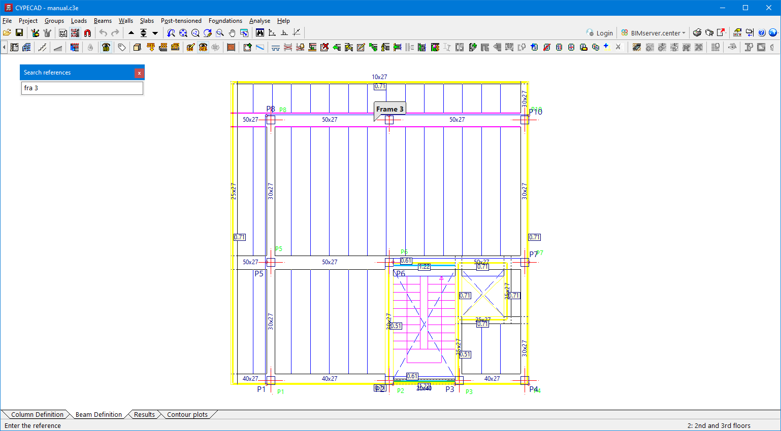
Reference search
In CYPECAD version 2025.a, the "Groups-Search references" option has been added.
This allows users to search for elements (columns, walls, frames, slabs, beam intersections and predefined loads) by their reference.
Only the reference, or part of it, needs to be entered for the element to be located.
Beams and slabs can also be searched for with the "Beam 1" ("Slab 1") format.
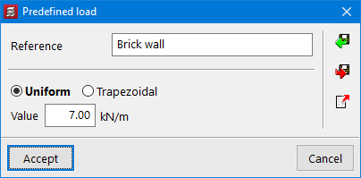
Predefined loads
In the options for entering loads on the floor ("Loads", "Line loads on beams", "Surface loads on slabs"), the possibility of predefining these loads has been added so they can be entered more easily.
Furthermore, if any changes are made to the value of the load, they will be much quicker and there will be less chance of mistakes.
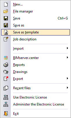
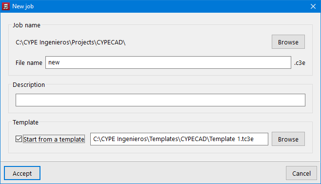
Job templates
In the "File" menu of CYPECAD version 2025.a, the "Save as template" option has been added.
This new option allows the configuration and general data of a job to be stored in templates and used later when creating new jobs.
Saved templates can be used when creating a new job by selecting the "Start from a template" option.
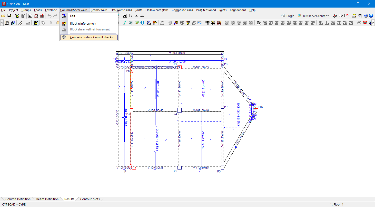
Checking the requirements for the seismic design of reinforced concrete nodes (new CYPECAD module)
As of version 2025.a, CYPECAD verifies the requirements for the seismic design to be met by the beam-column nodes of reinforced concrete frames that are part of the seismic force resisting system.
These checks for reinforced concrete nodes have been implemented for the following codes:
- ACI 318-08
- ACI 318-11
- ACI 318-14
- ACI 318-19
- NSR-10 (Colombia)
- NTRC-17 (Mexico)
- NB 1225001-1:2020 (Bolivia)
- Eurocode 8
- Spanish structural code "Código Estructural"
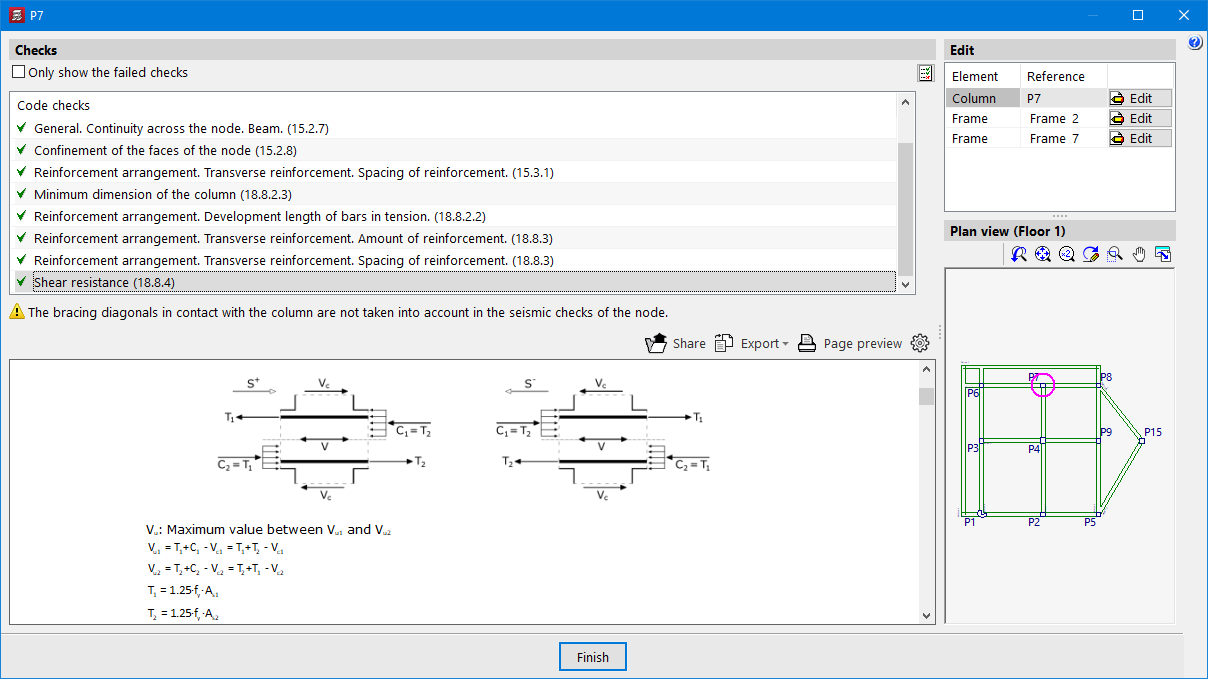
In the "Columns/Shear walls" menu of the "Results" tab, there is a new option: "Concrete nodes - Consult checks" which allows users to consult all the checks carried out in the selected node.
This option also allows users to access the corresponding editors, if necessary, in order to modify the reinforcement of the beams and columns at the node.
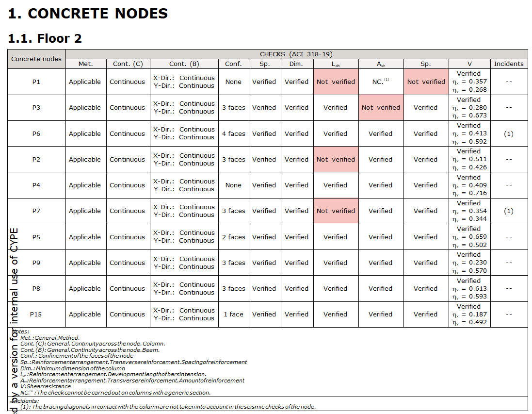
The "ULS checks" report has been extended with the corresponding tables summarising the status of the checks of the concrete nodes.
If not all checks are met at a node, a corresponding warning is displayed in the final analysis report, similar to the errors and warnings for other elements.
Options bar for the layout of the model components
As of version 2025.a, IFC Builder and the applications that include the "3D Model" tab have an options bar for the layout of the model components, the same as the one available in applications with a 3D environment.
This way, the tools related to the entry of the new element are anchored below the application's toolbar.
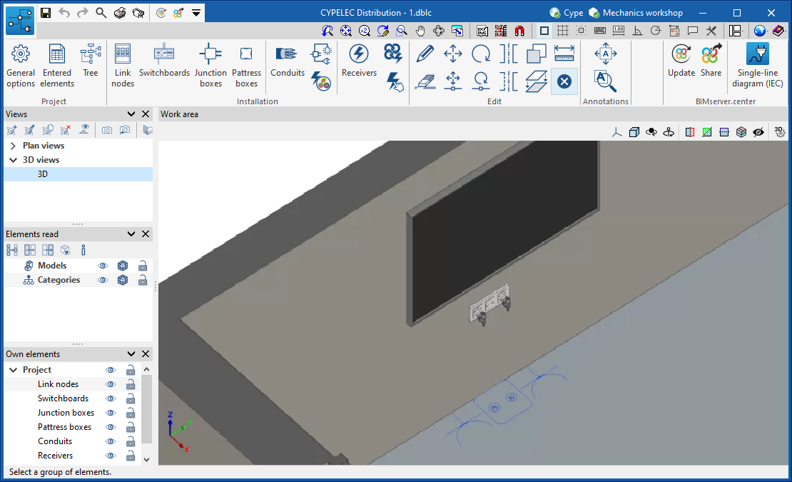
Direct reading of the symbols
CYPELEC Distribution displays the symbols used in CYPELEC Electrical Mechanisms without having to enter them again. To do this, when the job is created in CYPELEC Distribution, it must be linked to a BIM project containing information from CYPELEC Electrical Mechanisms.
These symbols are transferred as a template in DWG format so that they can be deactivated in the "Template views manager".
Creating views
To make it easier to view the diagram, views of the single-line diagram have been added.
The "Views" group is located on the left-hand side of the interface and will always include the "MAIN" view, which corresponds to the complete single-line diagram.
The procedure for creating a new view can be started by clicking on the "Create a view based on the selected line" icon. Then the line is selected from which a partial view of the diagram is to be generated. The new view will appear in the list and can be selected for detailed viewing.
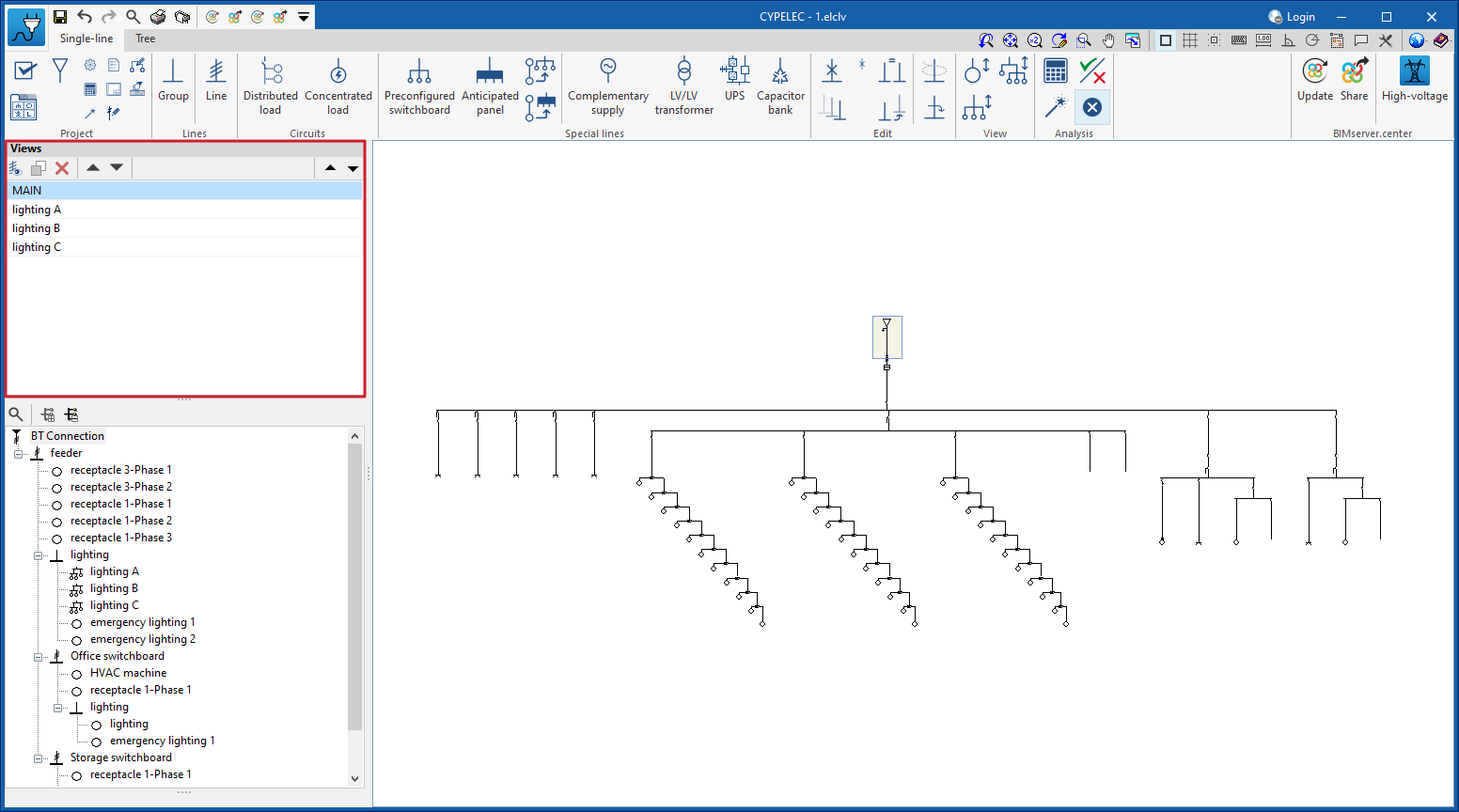
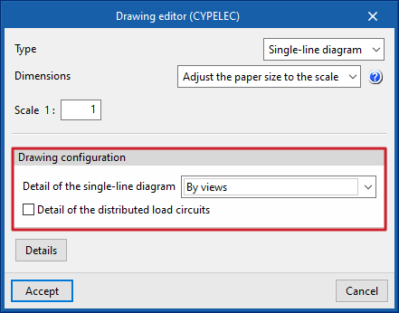
The list of views created can then be used to generate the drawings. To do this, select the "By views" option in the "Detail of the single-line diagram" option of the "Drawing editor" dialogue box.
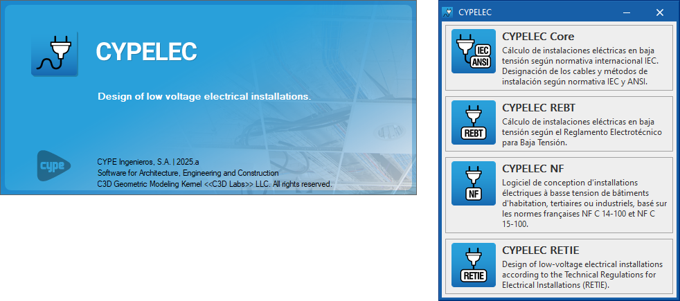
Combining the CYPELEC Core, CYPELEC REBT, CYPELEC NF and CYPELEC RETIE programs
As of version 2025.a, the CYPELEC Core, CYPELEC REBT, CYPELEC NF and CYPELEC RETIE programs are combined into a single program called CYPELEC.
When starting the CYPELEC program, a selection window appears in which the user must select the option corresponding to the code to be applied in the design of the low-voltage electrical system.
CYPELEC allows users to open jobs from previous versions of CYPELEC Core, CYPELEC REBT, CYPELEC NF and CYPELEC RETIE.
New 3D work environment
As of version 2025.a, developing telecommunications infrastructures in CYPETEL Systems can be carried out in a 3D work environment.
The elements and conduits of the installation can be included via the "3D view" or the different work planes. Each element type corresponds to a model layer, and its visibility can be activated or deactivated independently. It has a 2D display mode for the elements to make it easier to interpret them in the drawings exported by the program.
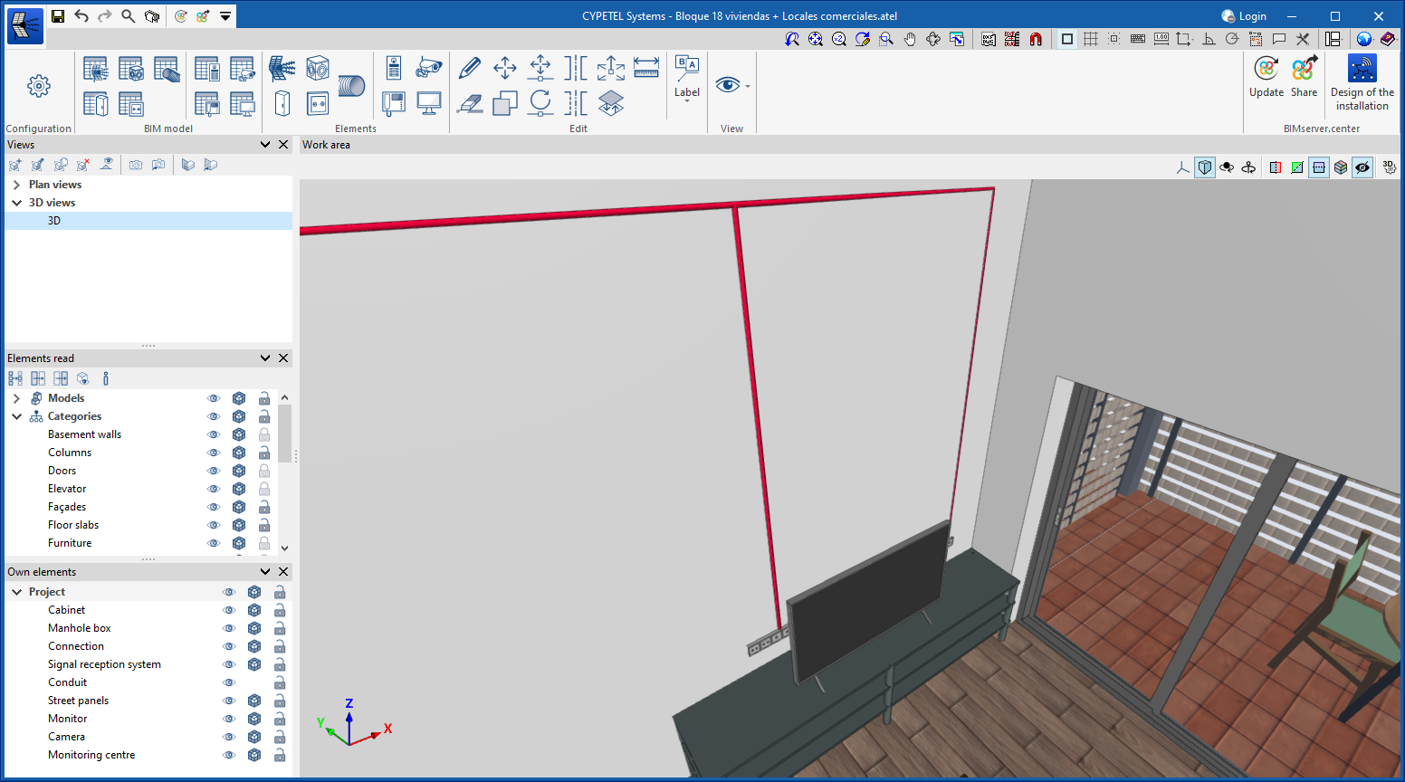
The program allows users to continue working on 2D templates from the BIM model or imported from the program in DXF, DWG, and DWF formats, as well as in various image formats (JPEG, JPG, PNG or WMF). This way, working compatibility is maintained in projects that do not have a 3D architectural model.
The reading of jobs produced with previous versions of the program will not be affected by this modification.
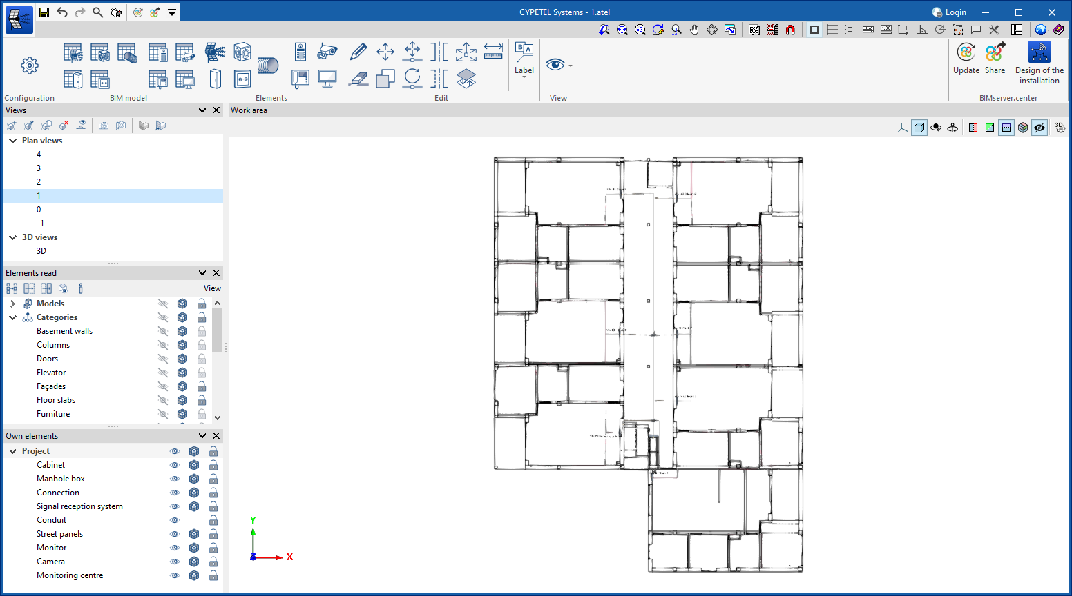
Thanks to this new 3D environment, which allows contributions of urban area maps from Open BIM Site to be displayed, and to the implementation of the UNE 133100-6 standard in this version 2025.a, users can carry out urban infrastructure deployment projects for telecommunications networks in CYPETEL Systems.
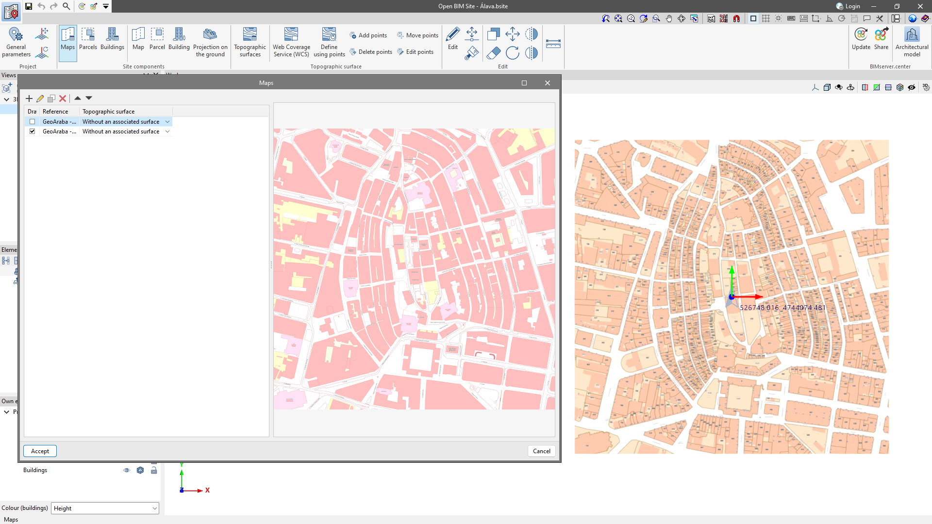
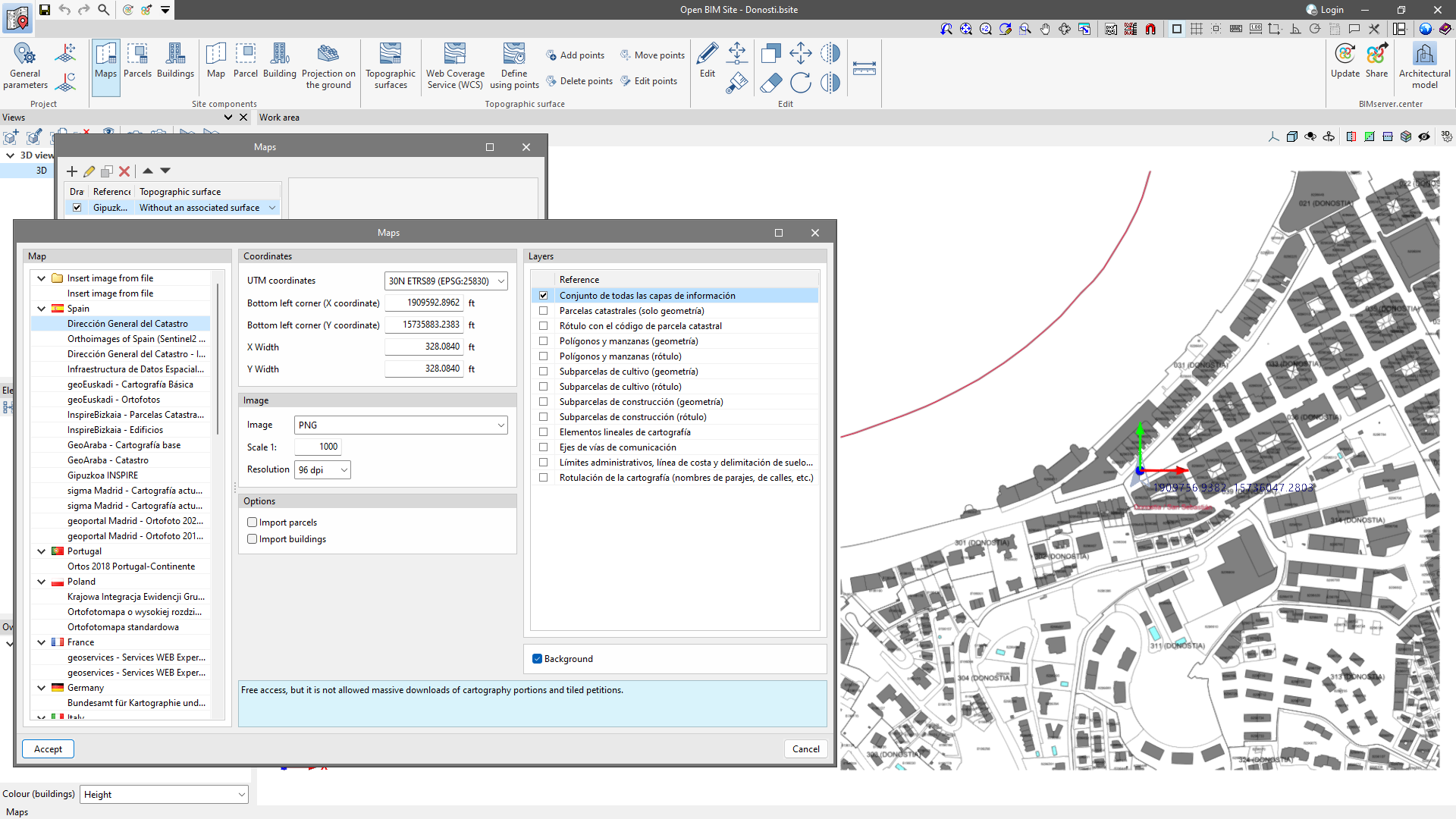
New WMS services for obtaining maps
As of version 2025.a, Open BIM Site allows users to obtain maps via WMS services from the following data sources:
- Spain
- InspireBizkaia - Parcelas Catastrales y Direcciones
- InspireBizkaia - Edificios
- GeoAraba - Cartografía base
- GeoAraba - Catastro
- Gipuzkoa INSPIRE
- Belgium
- Federal Public Service Finance - Cadastral Layers
- CartoWeb NGI IGN
- Orthophotos NGI IGN
- INSPIRE viewer NGI IGN
- The Netherlands
- PDOK Kadastrale Percelen INSPIRE
- PDOK Kadastrale Percelen INSPIRE
- Greece
- GeoData Orthophotos Greece
- GeoData Orthophotos Greece
- Argentina
- IGN Vuelos fotogrametricos con avión
- IGN Vuelos fotogrametricos con VANT
- IGN Capas vectoriales
- Mexico
- Atlas Cibernético
- INEGI
- Brazil
- MP - Ministério de Planejamento, Desenvolvimento e Gestão
- MP - Ministério de Planejamento, Desenvolvimento e Gestão
- Panama
- IGN Tommy Guardia Datos fundamentales de la República de Panamá 2014
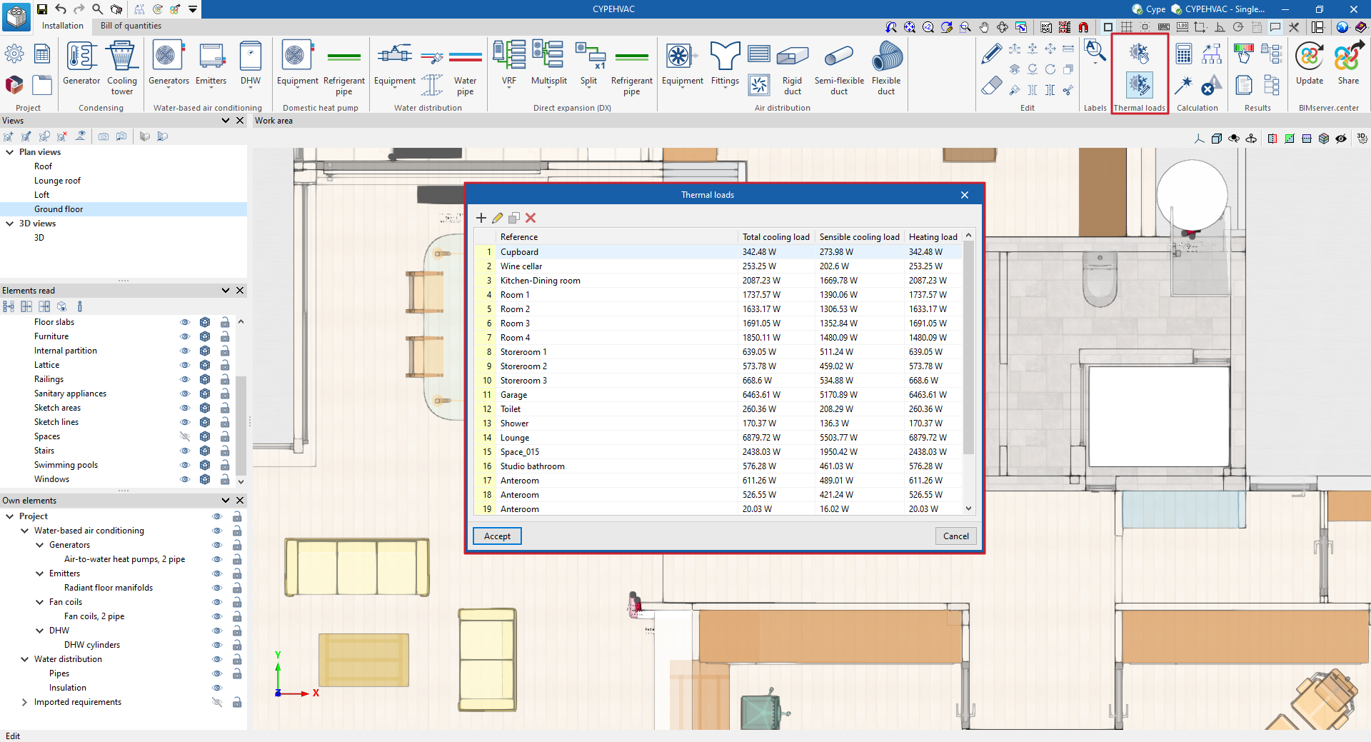
Changes in the management of imported thermal loads
This version of CYPEHVAC slightly modifies the management of the relationships between the imported thermal loads and the terminal elements of the system. Now, the parameters of the terminal units include the "Assigned thermal loads", i.e. the loads to which they will contribute their power and from which the power requirements to be contributed and design temperatures will be extracted:
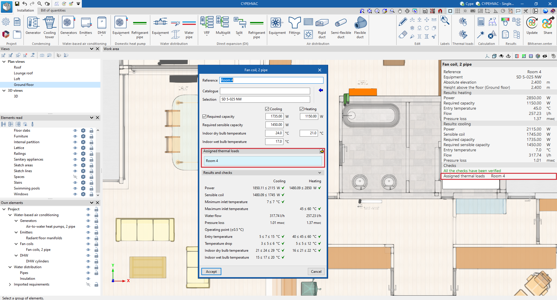
The program allows users to import thermal loads from the BIM model, in which case they will have an associated geometry and the program will allow them to be associated to the units automatically, by means of their layout. But, as a new feature, it will also allow them to be created without associated geometry with the "Thermal loads" option in the tools menu. In this case, the users will have to associate them to each unit with the "Assign thermal loads" option:
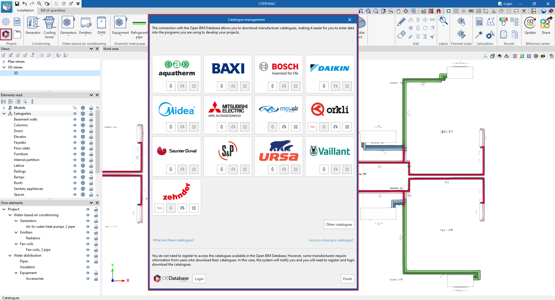
New management of equipment manufacturers and libraries
As of version 2025.a, the program divides the management of equipment and products that can be selected for the system design into library elements and manufacturer elements:
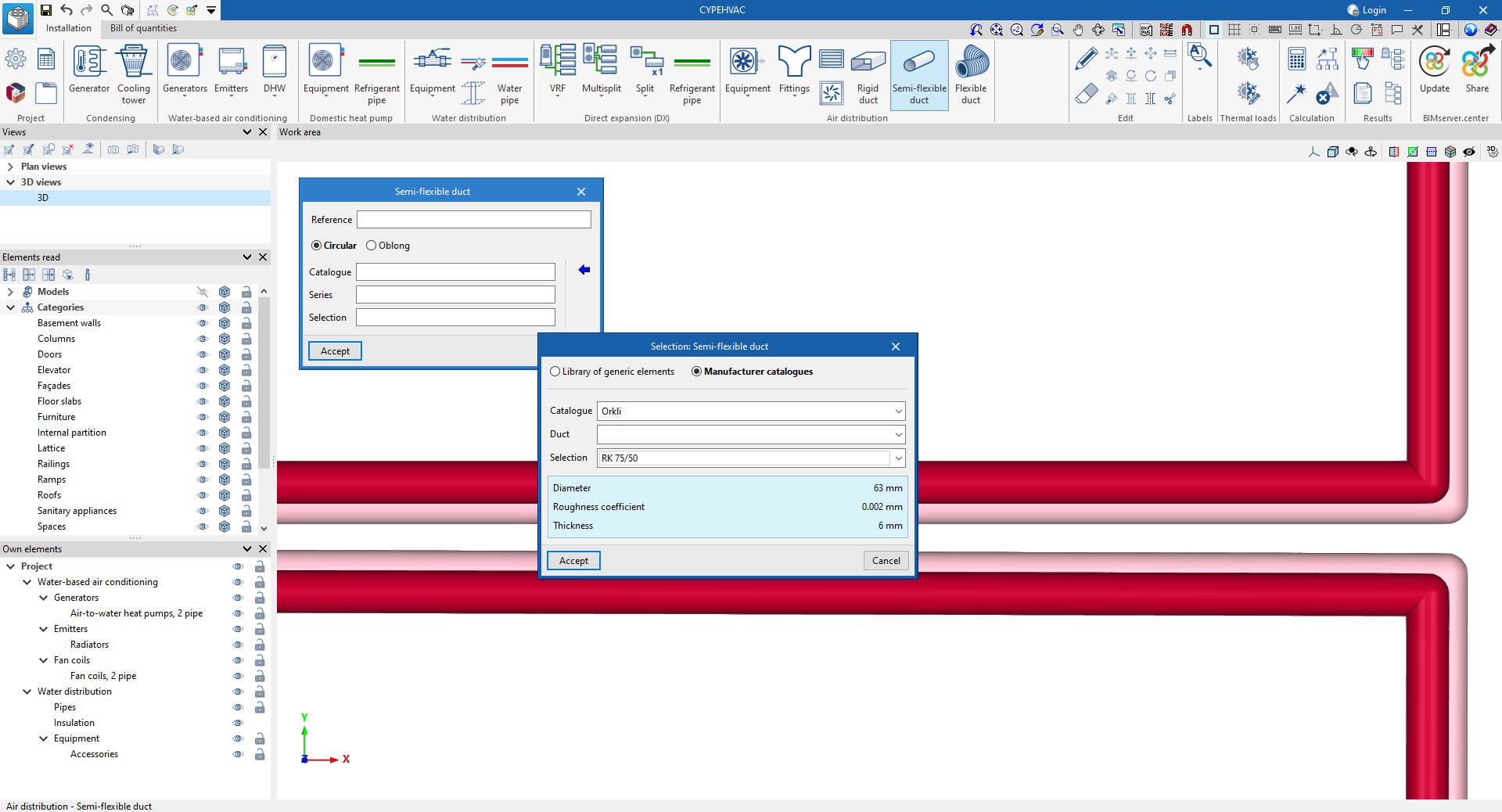
For manufacturer elements, the program allows users to download catalogues with all the data necessary for the design, via the connection to the Open BIM Database. The control of the downloaded catalogues is carried out from the "Catalogue management" option in the program:
New groups and applications. Installing and uninstalling
In version 2025.a, CYPE Menu (which can now be downloaded exclusively from the BIMserver.center platform) has new program groups.
- Architecture
- Structures
- MEP (Mechanical and Plumbing)
- MEP (Electrical)
- Energy and acoustic simulations
- Project management
- Project documents
- Interoperability
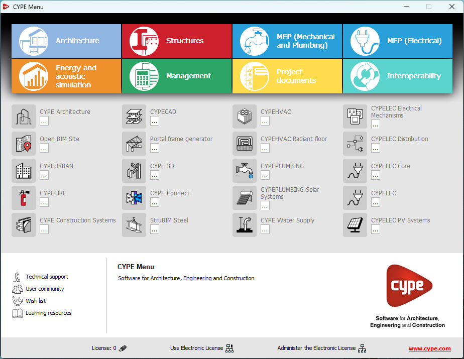
Most of the CYPE applications are sorted into these groups. In previous versions, most of these applications could only be downloaded as single applications from the BIMserver.center platform.
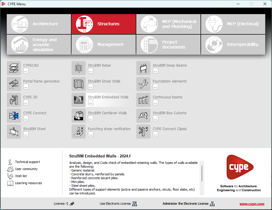
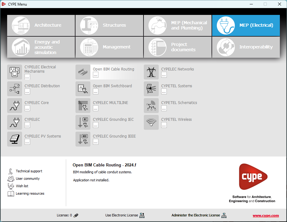
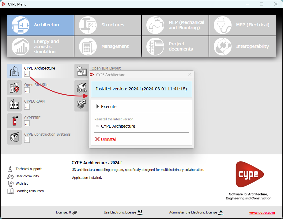
By downloading and installing CYPE Menu, users will only have the CYPE programs menu installed, but none of the applications included in it will be downloaded or installed. Initially, each of the icons representing the CYPE Menu applications appears in a box with a grey background. When clicking on any of them for the first time (or on the button under the application's name), a contextual menu will appear allowing users to download and install the latest version of that application or an earlier version if available. Earlier versions (from 2024 onwards) will be available for those programs that include paid modules. Normally, free applications will only allow the latest version of these programs to be installed. Any installed version of any application can be uninstalled.
When an application has been installed, by clicking on the button under its name, the context menu that appears includes the "Uninstall" option.
More information on this program menu can be found in the FAQ "How to download and install programs from CYPE’s general menu".
The CYPE Menu download of versions before 2025 (with the applications included) is still available in the download area of the CYPE website.
CYPE Menu. Exclusive download from the BIMserver.center platform
As of version 2025.a, the CYPE program menu can only be downloaded from the BIMserver.center platform.
The CYPE Menu application was already available from version 2024.b on the BIMserver.center platform. Now, in version 2025.a, the advantages of CYPE Menu compared to previous versions, which were downloaded from the download area of the CYPE website, are as follows:
- As of version 2024.b
- Once CYPE Menu has been installed, the applications it contains will be installed from this new menu when they are opened for the first time.
- Once CYPE Menu has been installed, the applications it contains will be installed from this new menu when they are opened for the first time.
- As of version 2024.f
- CYPE Menu allows users to manage the updates of the applications it contains.
- CYPE Menu allows users to manage the updates of the applications it contains.
- As of version 2025.a
- New program groups and many CYPE applications that could only be downloaded directly from BIMserver.center are included.
- The version of each application to be installed can be selected (from version 2024 onwards).
- Previously installed applications can be uninstalled.
Further information on the new features can be found in the following new features of CYPE Menu version 2025.a.
In the download area of the CYPE website, the download of the program menu for versions prior to 2025.a (in 64-bit and 32-bit) will still be available. In this download area, there is also a link to the BIMserver.center platform "Store" for downloading the 2025.a version of "CYPE Menu".
As a result of these changes, the 32-bit version of the CYPE Menu is no longer available in version 2025.a. As of 18 February 2019 (version 2019.f), the CYPE programs have been running on 64-bit systems. Since then, only the classic CYPE menu could be installed on 32-bit systems. All other applications (downloadable from the BIMserver.center platform) only worked on 64-bit systems. We believe that 32-bit programming is no longer feasible to take advantage of the superior performance of 64-bit processors and operating systems. Users who still want to use certain 32-bit CYPE programs (those available in the "CYPE Menu" prior to version 2025.a) must install a version prior to 2025.a from the download area of the CYPE website, but will not be able to upgrade their programs to later versions. Please refer to our FAQ question "Which version should I download, 64-bit or 32-bit?" for more information on the 32-bit and 64-bit versions.