Air-air conditioning systems. Air handling unit, variable airflow system
In variable airflow systems, the air conditioner has a variable speed fan. The power delivered to the zones is adjusted at the terminal units (variable flow units) by varying the air flow rate. The supply temperature can be controlled in several ways. The fan will always be running.
EnergyPlus™ variable airflow systems are designed to operate with a terminal reheat for heating control.
Air handling unit, variable airflow system. “Air conditioning” tab
Cooling (optional)
- Cooling coil (Direct expansion / Cold water)
This sets the characteristics of the cooling coil:- Supply air flow
- Gross rated capacity (optional)
- Gross rated sensible heat ratio (optional)
The gross rated sensible heat ratio is the ratio of the nominal sensible capacity to the gross rated capacity. - Nominal cooling COP
- Cold water
- Chilled-water system
Allows users to select a chilled-water system defined in the "Air conditioning systems" section.
- Chilled-water system
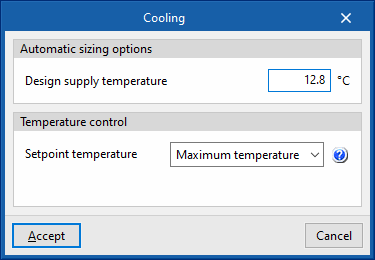
- Advanced configuration
- Automatic sizing options
- Design supply temperature
- Temperature control (Maximum temperature / Minimum temperature)
- Maximum temperature
This option calculates the supply air temperature needed to overcome the cooling demand of the critical zone at the maximum supply flow rate. This temperature shall be as high as possible. Therefore, this strategy minimises the cooling generator consumption in exchange for higher fan consumption. - Minimum temperature
This option calculates the supply air temperature needed to overcome the cooling demand of the critical zone at the maximum supply flow rate. This temperature shall be as low as possible. Therefore, this strategy minimises the cooling generator consumption in exchange for higher fan consumption.- Minimum air flow fraction
The minimum air flow fraction must match the one defined in the terminal units connected to this unit.
- Minimum air flow fraction
- Maximum temperature
- Automatic sizing options
- Supply air flow
Heating (optional)
- Heating coil (Direct expansion / Electric / Gas / Hot water)
This sets the characteristics of the heating coil:- Direct expansion
- Gross rated capacity (optional)
- Gross rated heating COP
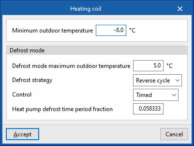
- Advanced configuration
- Minimum outdoor temperature
- Defrost mode
- Defrost mode maximum outdoor temperature
- Defrost strategy (Reverse cycle / Resistive)
- Control (Timed / On demand)
- Heat pump defrost time period fraction
- Electric
- Gross rated capacity (optional)
- Gas
- Gross rated capacity (optional)
- Advanced configuration
- Gas heating coil efficiency
- Parasitic electric load
- Hot water
- Hot-water system
Allows users to select a hot-water system defined in the "Air conditioning systems" section.
- Hot-water system
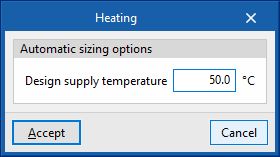
- Advanced configuration
- Automatic sizing options
- Design supply temperature
- Automatic sizing options
- Direct expansion
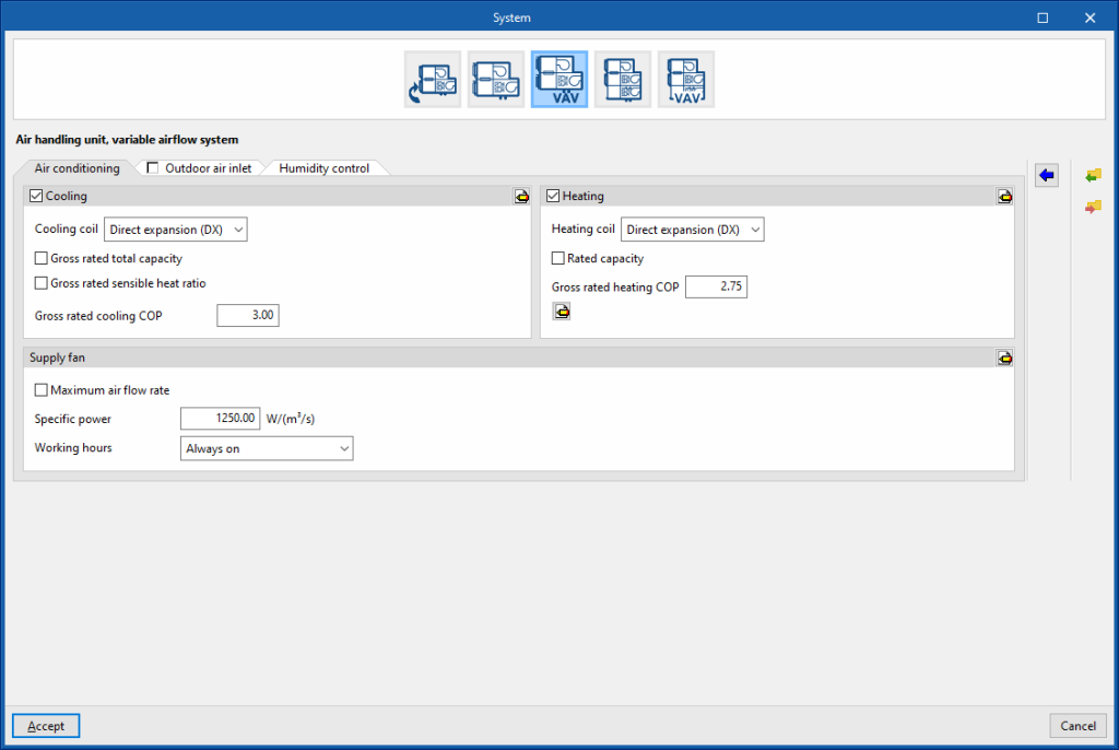
Supply fan
- Maximum air flow rate (optional)
- Specific power
- Working hours (Always on / Only with active ventilation)
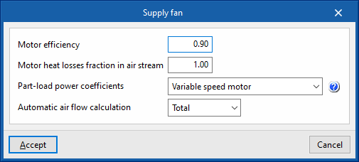
- Advanced configuration
- Motor efficiency
- Motor heat losses fraction in air stream
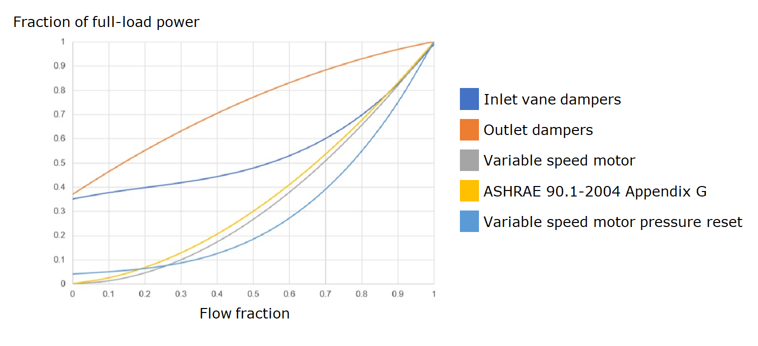
- Part-load power coefficients (Inlet vane dampers / Outlet dampers / Variable speed motor / ASHRAE 90.1-2004 Appendix G / Variable speed motor pressure reset)
- Automatic air flow calculation (Simultaneous / Total)
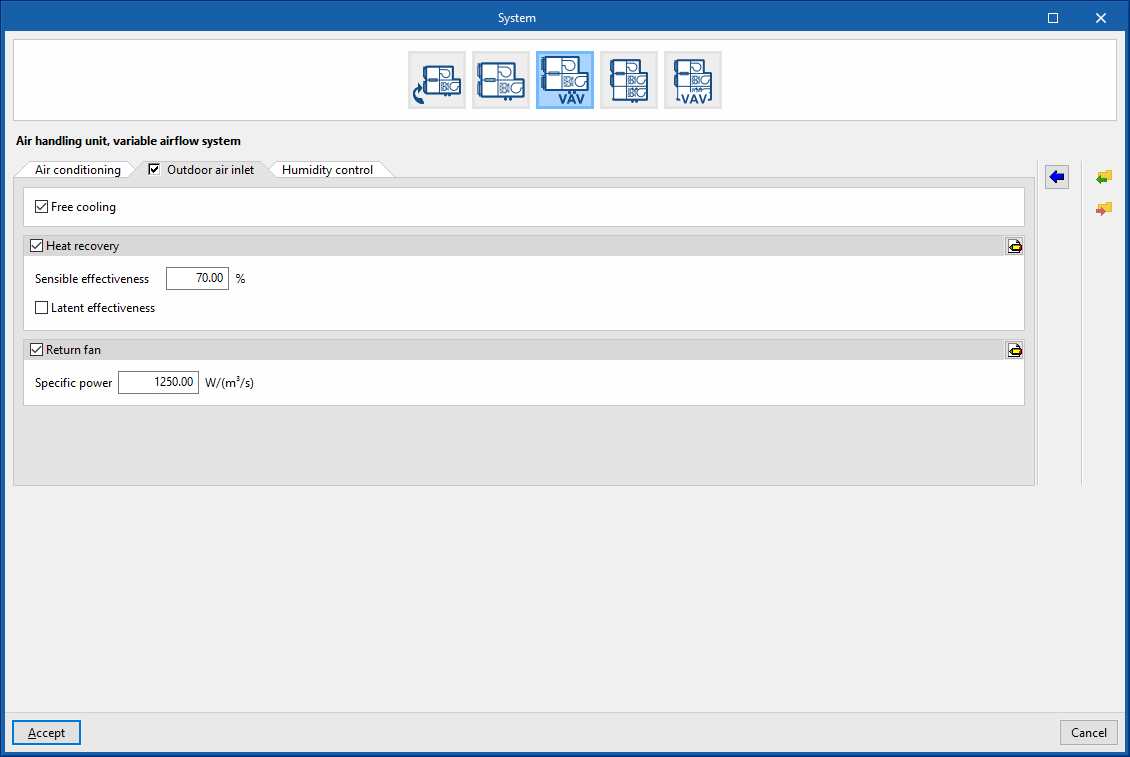
Air handling unit, variable airflow system. “Outdoor air inlet” tab
If the “Outdoor air inlet” tab is deactivated, the system only recirculates air from the heating zones.
Free cooling (optional)
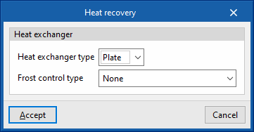
Heat recovery (optional)
- Sensible effectiveness
- Latent effectiveness (optional)
- Advanced configuration
- Heat exchanger type (Plate / Rotary)
- Frost control type (None / Exhaust air recirculation / Exhaust only / Minimum exhaust temperature)
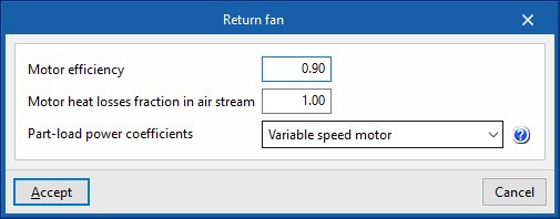
Supply fan (optional)
- Specific power
- Advanced configuration
- Motor efficiency
- Motor heat losses fraction in air stream
- Part-load power coefficients (Inlet vane dampers / Outlet dampers / Variable speed motor / ASHRAE 90.1-2004 Appendix G / Variable speed motor pressure reset)
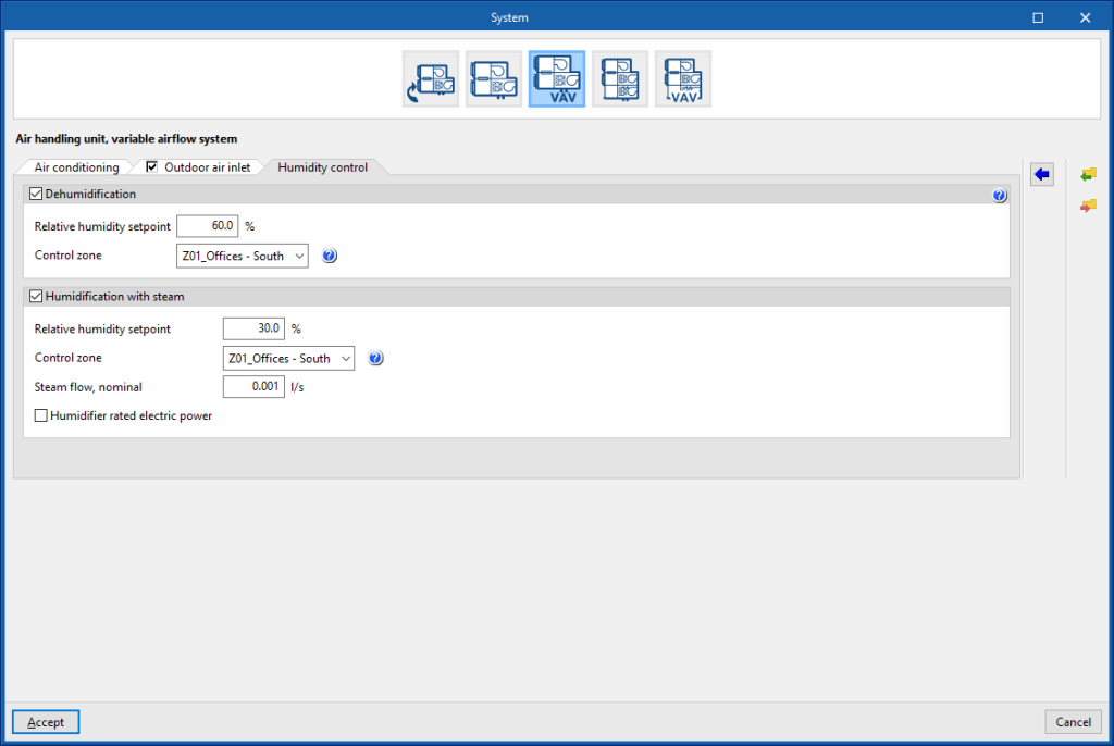
Air handling unit, variable airflow system. “Humidity control” tab
Dehumidification (optional)
The dehumidification of the air is carried out by its cooling and subsequent reheating.
- Relative humidity setpoint
- Control zone
The control zone is that which contains the thermostat associated with this equipment. A zone that contains a terminal unit connected to this equipment must be selected.
Humidification with steam (optional)
- Relative humidity setpoint
- Control zone
The control zone is that which contains the thermostat associated with this equipment. A zone that contains a terminal unit connected to this equipment must be selected. - Steam flow, nominal
- Humidifier rated electric power (optional)