
Generating and creating diagrams of the water supply system
The "Diagrams" tab, available at the top of the "Water Systems" tab, allows users to automatically generate diagrams of the water supply system from the model information developed in the "Installation" tab, or to create them manually using the available drawing tools:
- To create the diagrams from scratch, the sheets of the required formats are first created using the options on the left-hand side. Then the elements in the diagram are entered in the work area on the right-hand side using the options in the top toolbar.
- To generate the diagrams automatically, the "New" option at the top is used. Then, the user is free to modify the generated diagrams on the work area by using the options in the top toolbar as well.
Composite diagrams can be selected in this tab to be printed together with the rest of the job drawings using the corresponding options.
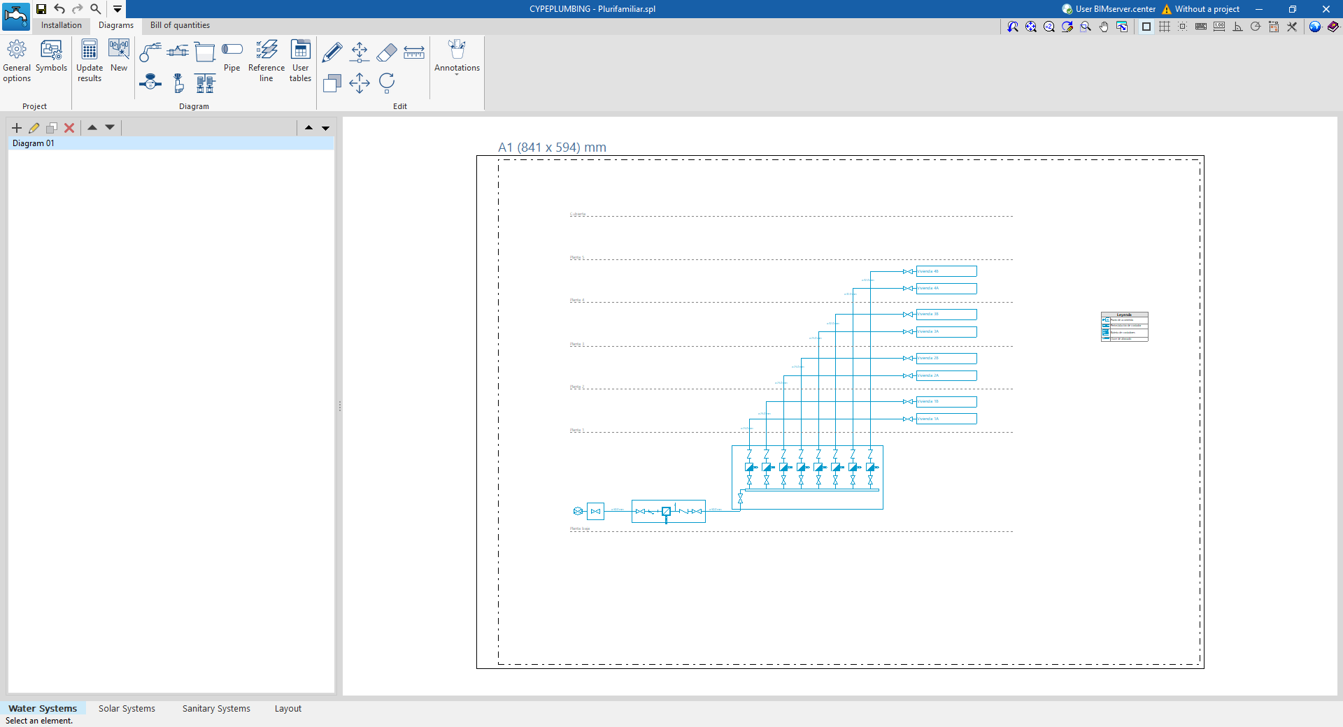
Diagram management
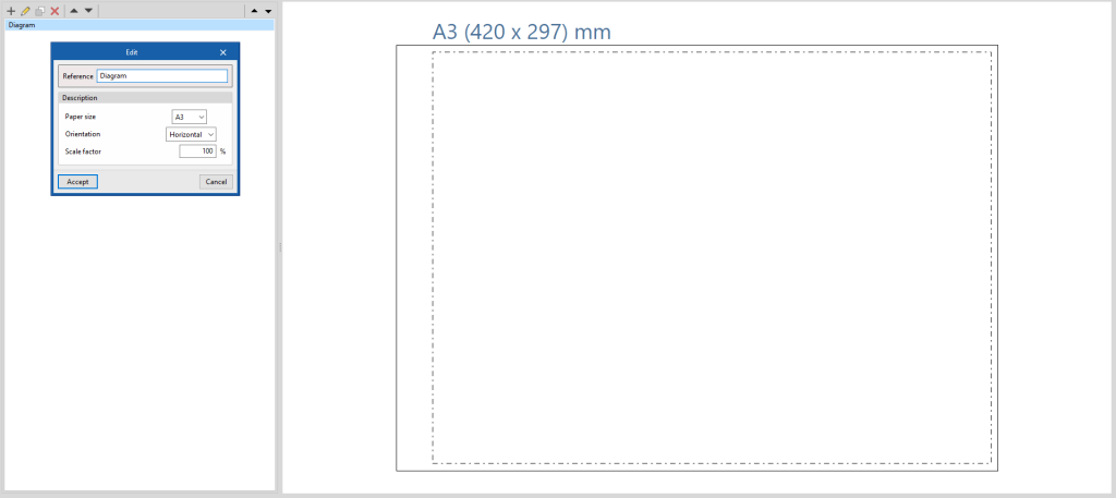
The diagrams of the water supply system are composed on sheets of different formats. The tools for creating and managing diagrams are located on the left-hand side of the interface.
The following features can be configured when creating or editing a diagram:
- Reference
- Description
- Paper size
The available paper sizes can be configured under "General options". - Orientation (Horizontal / Vertical)
- Scale factor (%)
Options in the "Project" group
In the "Project" group of the top toolbar, the program includes the following features:
General options
Used to configure the paper formats and types of table available, the units of measurement, and the graphic representation of the elements in the water supply system diagrams, defining their colour and symbols (generic or customised).
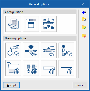
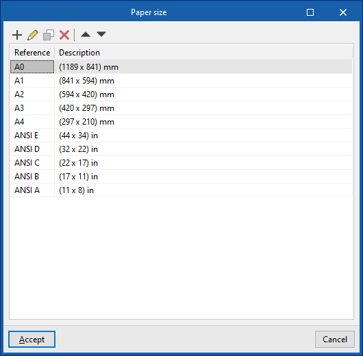
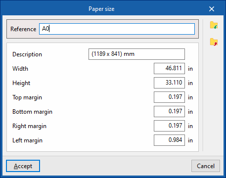
Paper size
Defines the available paper sizes entering the following parameters:
- Reference
- Description
- Width
- Height
- Top margin
- Bottom margin
- Right margin
- Left margin
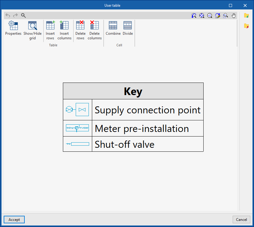
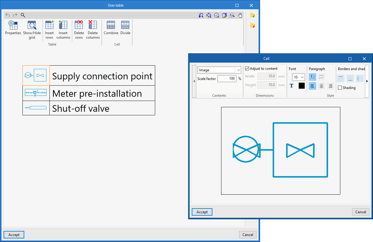
User table
Defines and edits the type of table.
When creating a table type, it can be "Generic", indicating the number of rows and tables and filling in the content of its cells in a free editor, or a "Key" type, in which case it is an "Automatic generation" can be carried out according to the elements arranged in the diagram.
The table types defined here can be used later when entering tables in the diagram via the "User tables" option in the top toolbar.
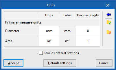
Units
Defines the units of the indicated magnitudes.
Drawing options
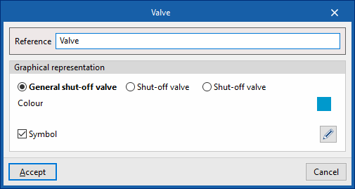
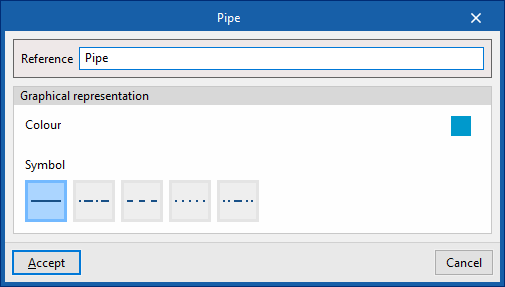
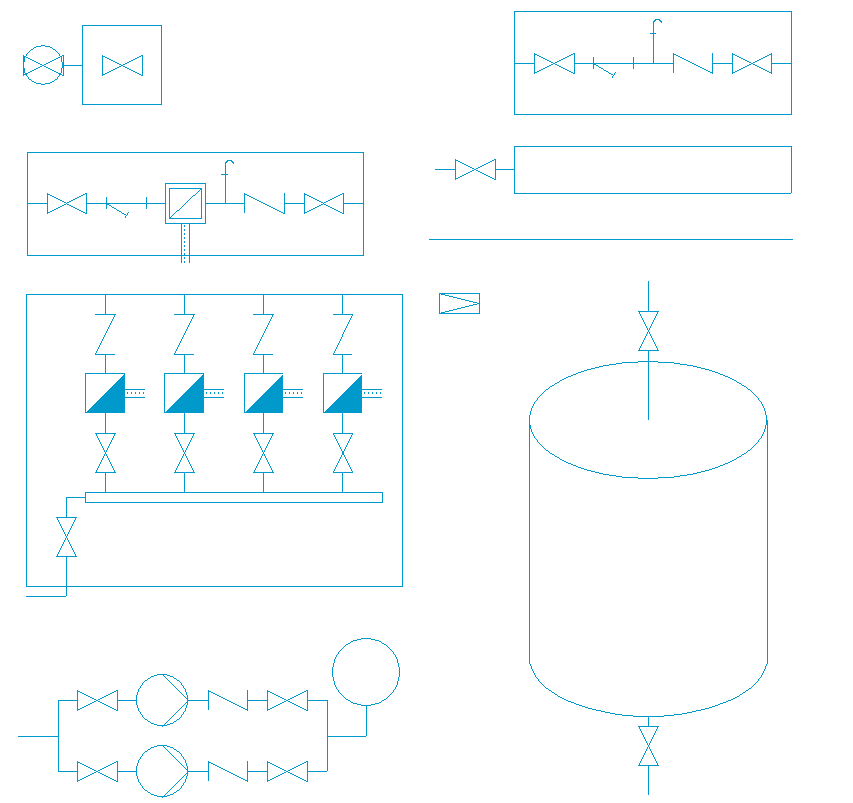
These options are used to define types of representation of the elements of the water supply system diagram, which can then be selected when entering these elements using the options in the "Diagram" group.
- Supply connection point, Meter, Pressure limiting valve, Tank, Booster set
- Reference
- Graphical representation
- Type selection
Selects the type of element from those available: - Colour
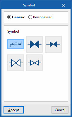
- Symbol (optional)
Selects a "Generic" or "Personalised" symbol from those previously created with the tools in the "Symbols" option.
- Type selection
- Pipes, Reference lines
- Reference
- Graphical representation
- Colour
Sets the colour of the line. - Symbol
Sets the style of the line.
- Colour
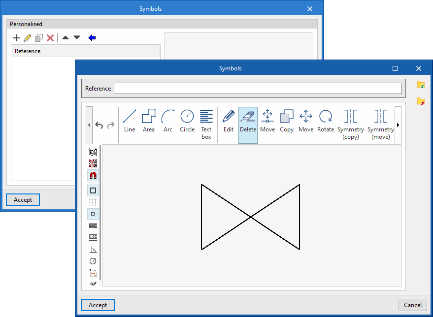
Symbols
Creates custom symbols using a drawing editor or imports symbols contained in DXF, DWG or DWF files saved on disk. These symbols can be selected in the settings defined for each element under "General options".
Options in the "Diagram" group
In the "Diagram" group of the top toolbar, the program includes the following tools:
Update results
Updates the information available for generating new diagrams with the analysis results.
New
Automatically generates the diagram of the water supply system if the model contains the appropriate information:
- In systems with more than one user, the program generates two diagrams, one from the supply connections to the meter assembly and the other from the assembly to the shut-off valve.
- In systems with one user, the program generates a diagram from the supply connection to the shut-off valve.
The diagrams generated can be modified later using the tools available at the top.
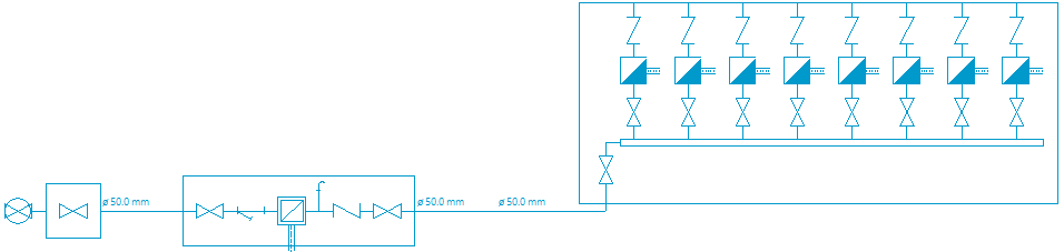
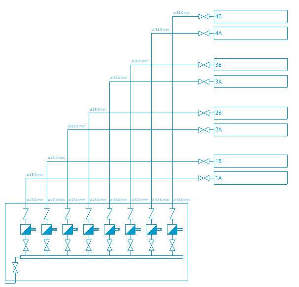
Diagrams generated for a multi-user system
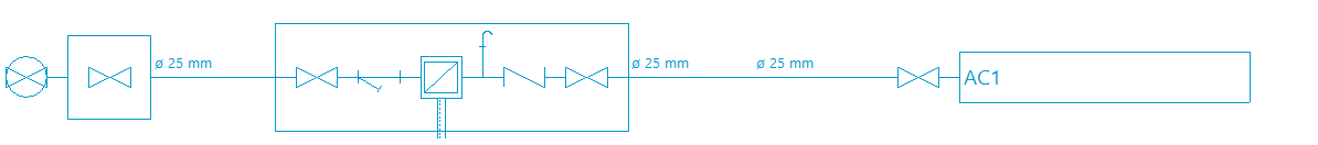
Diagram generated for a single-user system
Tools for entering diagram elements
These options allow users to freely enter the elements of the diagram of the water supply system, defining the following parameters:
- Supply connection point
- Reference
- Meter
- Reference
- Drawing options
- Shut-off valve
- Reference
- Drawing options
- Pressure limiting valve
- Reference
- Drawing options
- Tank
- Reference
- Drawing options
- Description
- Number of tanks in parallel
- Booster set
- Reference
- Drawing options
- Description
- Number of pumps
- Pipe
- Reference
- Drawing options
- Description
- Diameter
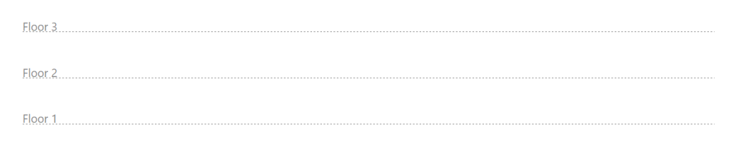
Reference line
Enters a reference line. These lines can be used to specify the layout of the elements in the diagram on the different floors of the building.
User tables
Inserts legends or tables with complementary information in the diagrams.
When creating a table, it can be "Generic", specifying the number of rows and tables and filling in the content of its cells in a free editor, or "Legend" type, where "Automatic generation" is possible depending on the elements arranged in the diagram.
Table types can also be managed via the corresponding option in the "General options".
Options in the "Edit" group
Editing tools
The options in this menu allow the following editing operations to be carried out on the elements in the system diagram:
| Edit | Edits the parametric properties of the selected element in the model. | |
| Copy | Creates a copy of one or more elements. | |
| Move element | Moves an element or a node of an element. | |
| Move a group of elements | Moves a group of elements. | |
| Delete | Deletes a previously entered element. | |
| Rotate | Rotates an element. | |
| Measure lengths on plan | Measures lengths and angles between points defined in the model. If a closed outline is selected, it also indicates the area. |
Drawing tools
The options in this menu allow the following drawing resources to be entered:
| Elevation | Enters an elevation between two selected points, indicating the line colour, line thickness, and text size. | |
| Line | Inserts a line between two selected points, indicating its colour and thickness. | |
| Text | Enters a text and a reference line, indicating its colour, the line thickness and the text size. | |
| Text box | Enter a left-aligned, right-aligned or centred text box, indicating the colour and size of the text, the properties of the frame and the background fill. | |
| Arc | Enter an arc and, optionally, its radius, indicating the line colour, line thickness and text size. | |
| Circle | Enter a circle and, optionally, its radius or diameter, indicating the line colour, line thickness, and text size. | |
| Rectangle | Enter a rectangle and, optionally, its area, indicating the line colour, line thickness and text size. | |
| Area | Enter a dotted polygon and, optionally, its area, indicating the line colour, line thickness, and text size. | |
| Polyline | Inserts a polyline by points, indicating its colour and thickness. | |
| Edit | Edit the properties of the selected drawing resource. | |
| Delete | Deletes the selected drawing resources. | |
| Move | Moves the selected drawing resource or parts of it. | |
| Assign | Assigns the properties of a drawing resource to others. When selecting a drawing resource, resources with the same properties are highlighted in orange. |