Generating and editing drawings in CYPE programs
The drawings of the CYPE programs detail the elements entered in the model and allow the information to be obtained in different formats to complete the project.
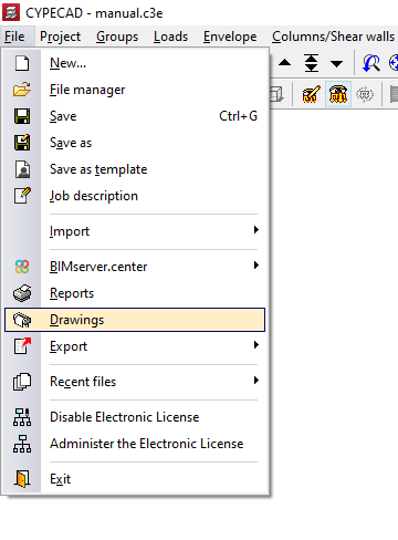
Generally, to access the printing of drawings, open the "File" menu and select the "Drawings" option, or click directly on the "Drawings" button available at the top of the program interface.
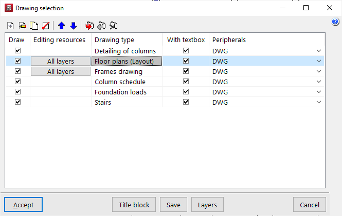
This opens the "Drawing selection" window, which is detailed below.
Note:
In some programs, using the "Drawings" option opens the "Edit sheets" pop-up window instead, which offers different features that make advanced layout of the project's sheets possible. Detailed information on the "Edit sheets" window can be found in the following link.
Selecting drawings
The "Drawing selection" window manages the report of the list of job drawings.
The first option in the top toolbar can be used to "Add" a drawing. This will open the "Edit drawing" window, where the desired drawing is chosen and configured.
After accepting the "Edit drawing" window, the drawing is added to the report in the "Drawing selection" window. This process must be repeated to add all the desired plans for the job.
At the top, the program offers tools to "Edit", "Copy", "Delete" and move drawings from the list.
If available, the "Export drawing series", "Import drawing series" and "Delete drawing series" options allow the list of entered drawings and their configuration to be saved on disk.
The list of drawings is organised as a table with different columns, which work as follows:
- Draw
The program will print the drawings that have the "Draw" checkbox activated. - Editing resources
Incorporates the editing resources entered into the drawing. - Drawing type
Provides information on the type of drawing selected. - Name
Name of the drawing. - With textbox
Activating this checkbox will add a textbox to the drawing indicating the type of drawing and its scale. - Peripheral
Selects the peripheral device that will print the drawing. The drawings can be exported in DWG or DXF format or printed directly using graphic devices and printers configurable in the program, including export to PDF.
A number of additional options are displayed at the bottom of the window:
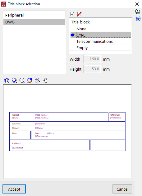
- The "Title block" option opens the "Title block selection" window, where users can use no title block ("None" option), import a title block from a DWG or DXF file (using the "Add" option at the top of the list of available title blocks), use a predefined title block by selecting it from the list, or reserve an "Empty" space in the drawing to manually add the title block later in another drawing program. This configuration is made for the selected peripheral.
- The "Save" option saves the drawing selection made and to exit the window without generating the drawings.
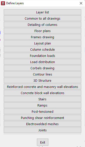
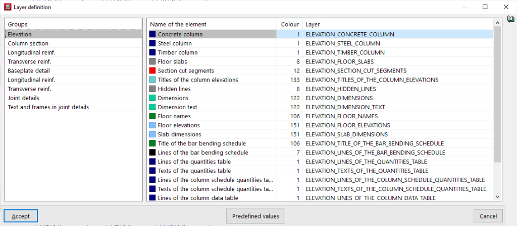
- From "Layers" the name and colour number of the layers generated in all types of drawing can be consulted and modified. The colour number can be associated with a different colour in each drawing program.
Drawing editor
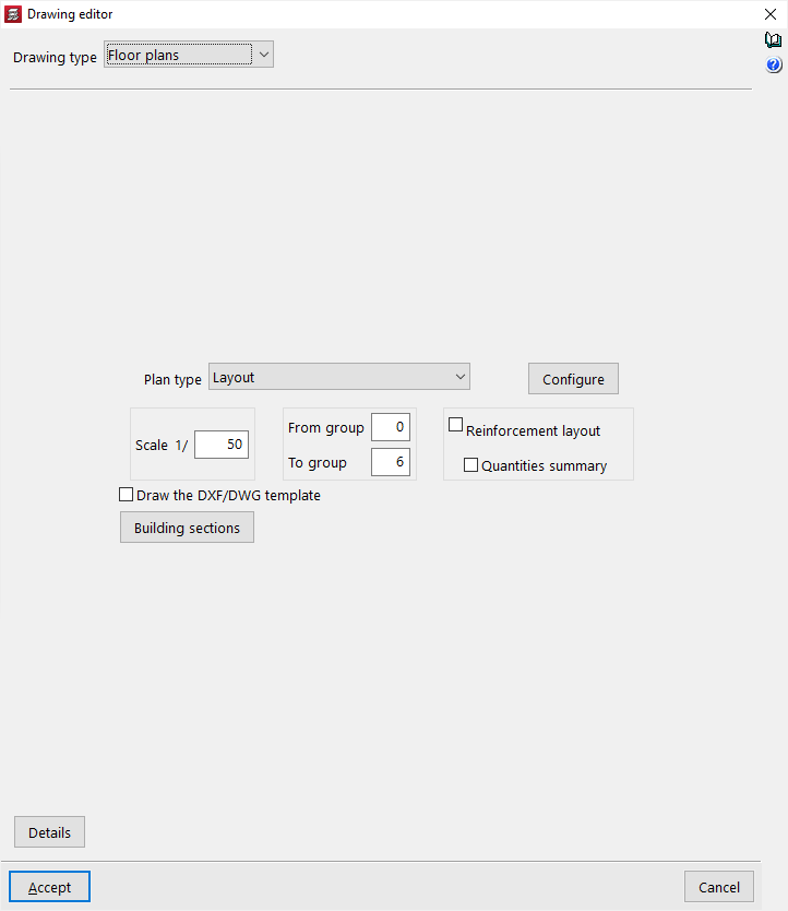
The "Drawing editor" window appears when adding a new drawing or editing an existing drawing from the "Drawing selection" window. Users can select the drawing to be generated and adjust its configuration.
In some programs, the job must be analysed so that all the drawings that the program can generate with the information in the model are available.
In this window, depending on the program being used, different detailed configuration options are shown where aspects such as the visibility of the different elements, the selection of groups to be printed, or the scale of the plan can be adjusted.
Details
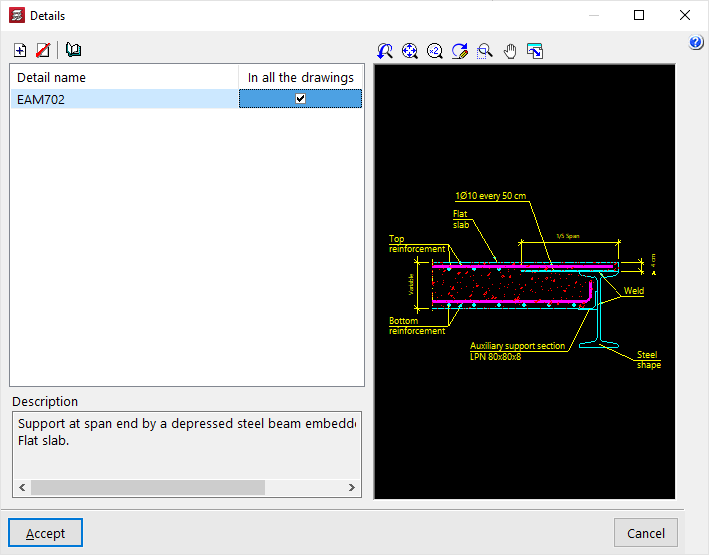
Optionally, construction details can be added to the drawing. To do this, click on "Details" at the bottom.
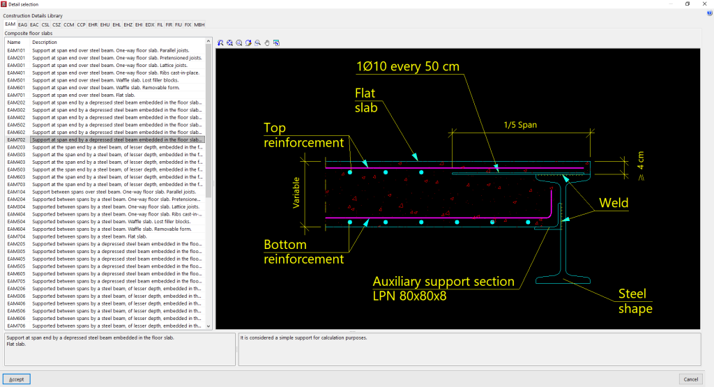
In the window of the same name, by clicking on "Add" users can access the "Construction Details Library" of the program, where all the available details are shown organised in different tabs. After selecting a detail, click on "Accept" to add it to the drawing. Users should indicate whether the detail is shown "In all drawings" or not.
It is also possible to "Add user information" by creating a detail library and loading it with DXF or DWG files saved on disk.
Laying out and printing drawings
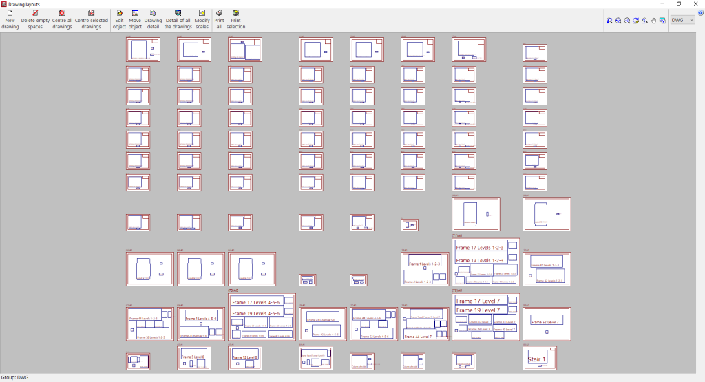
Once all the desired drawings have been loaded into the list, accepting the "Drawing selection" window leads to the "Drawing layouts" window, which offers a preview of the drawings to be generated and the drawings they contain.
Some limited operations can be performed in this window:
- New drawing
Creates a new drawing in the chosen format. - Delete empty spaces
Deletes empty drawings that do not contain drawings. - Centre all drawings
Restores the original drawing position of all drawings. - Centre selected drawings
Restores the original position of the drawings of the selected drawings. - Edit object
Moves elements (such as texts) within each drawing. - Move object
Moves selected drawings to change their position or placement in different drawings. - Modify scales
Changes the scale of some types of drawings (e.g. floor plans).
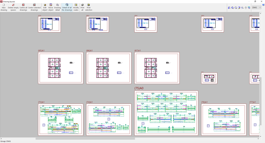
The pictures in the drawings are shown with no details so that the equipment consumes fewer resources and allows the above-mentioned operations to be carried out faster. To view the detailed content of the drawings, the following options are used:
- Drawing detail
Displays the detailed information contained in the selected drawing. - Detail of all the drawings
Displays the detailed information contained in all drawings.
Finally, the following options are available for printing the drawings:
- Print all
Prints all drawings. - Print selected
Prints only the selected drawings.
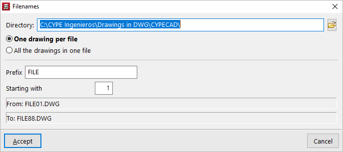
The program will ask for the "Directory" and "File name" if export to DXF or DWG files has been previously selected.
If several drawings have been selected, users can also choose whether each drawing is included in a separate file (which will generate a set of files), or whether all drawings are generated in a single file:
- Each drawing in one file
- All drawings in one single file
When accepted, the drawings will be generated in the selected directory. Optionally, if only one file is being generated, users can "Display the file with the associated program" by reading that file format.

