
Seismic design criteria by capacity
Seismic design criteria by capacity for supports and concrete beams
When a seismic analysis is carried out in CYPECAD, the program considers design criteria by the capacity of certain codes.
- For concrete supports, the program considers the design criteria for bending and shear capacity of the following codes:
- EHE‑08 - Anejo 10 (Spain)
- NCSE‑02 (Spain)
- IS 13920: 1993 (India)
Only shear capacity design criteria are available.
- ACI 318M‑08 (USA)
- NSR‑10 (Colombia)
- 1997 UBC (USA)
- CIRSOC 103‑2005 (Argentina)
With the combination of concrete regulation CIRSOC 201‑2005, and the seismic regulations CIRSOC 103‑2008 or CIRSOC 103‑1991.
- NTE E.060: 2009 (Peru)
- NEC -11 (Ecuador)
- PS 92 (France)
- PS 92 (version révisée 2010) (France)
- RPA 99/v 2003 (Algeria)
- RPS 2000 (Morocco)
- RPS 2011 (Morocco)
- For concrete beams, the program considers the shear capacity design criteria for the following codes:
- EHE‑08 - Anejo 10 (Spain)
- NCSE‑02 (Spain)
- IS 13920: 1993 (India)
- ACI 318M-08 (USA)
- NSR‑10 (Colombia)
- 1997 UBC (USA)
- CIRSOC 103‑2005 (Argentina)
With the combination of the concrete code CIRSOC 201‑2005, and the seismic codes CIRSOC 103‑2008 or CIRSOC 103‑1991.
- NTE E.060: 2009 (Peru)
- NEC -11 (Ecuador)
- PS 92 (France)
- PS 92 (version révisée 2010) (France)
- RPA 99/v 2003 (Algeria)
- RPS 2000 (Morocco)
- RPS 2011 (Morocco)
The design criteria by capacity are specified in the detailed reports of beam and concrete beam Ultimate Limit States.
In order for CYPECAD to take into account the capacity design criteria of the indicated earthquake codes, each one must be compatible with the concrete code selected in the job and allow the use of advanced beam and column editors. These compatibilities can be consulted in the “Available codes for the advanced beam editor” section on the “Concrete beams” page.
Seismic design criteria by capacity for slabs
The capacity checks carried out by CYPECAD automatically include the geometric and mechanical features of concrete columns and beams and, optionally, those of the slabs supported by beams reaching a column.
In order to define the geometric and mechanical features of these slabs, for the purpose of the capacity checks for concrete beams and columns, the “Assign data for the capacity check” option has been added (Beam definition tab > Beams/walls menu).
The aforementioned option will only be visible if a seismic analysis is carried out with a code for which the program includes capacity design criteria.
When this option is activated, a window appears where users can define the following data:
- Positive effective width
- Negative effective width
- Effective depth
- Mechanical steel area of the bottom reinforcement
- Mechanical steel area of the top reinforcement
Users can freely assign them to each one of the sides and edges of the beams reaching the columns. This allows the contemplation of cases in which the slabs have different geometric or mechanical features on each side of the beams or those in which there is not a slab on each side of the beam.
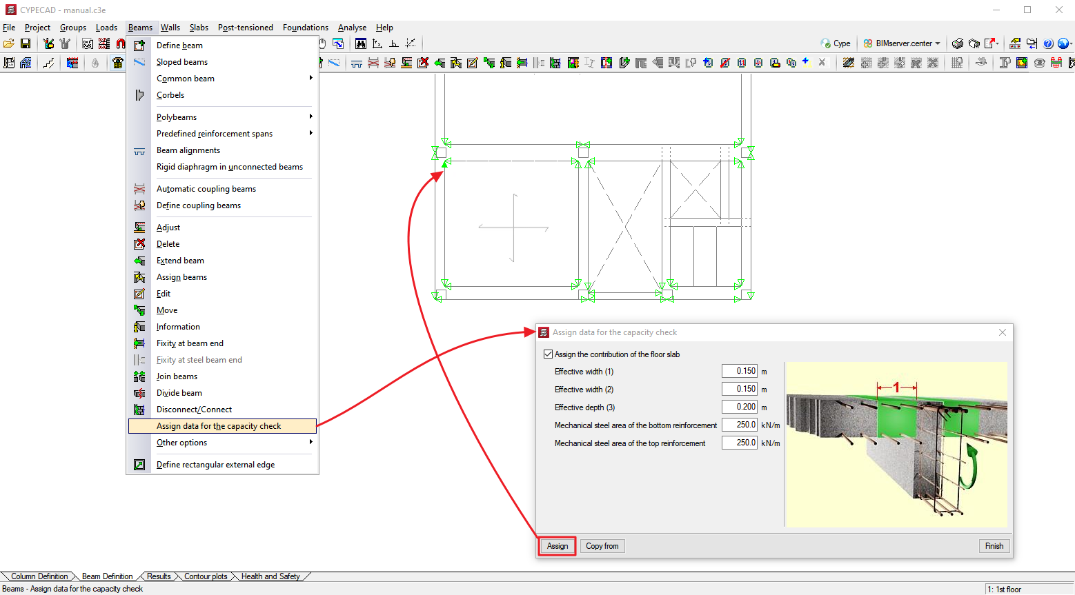
To identify each one of the sides and edges of the beams which have been assigned data for the capacity checks, the program draws small magenta triangles in the zones that are displayed when the “Assign data for the capacity check” option has been selected. The triangles will be green in the zones where the slab features have not been assigned, in which case, the dimensions and ratios of the slab will not be included in the capacity checks of concrete columns and beams.
