The joists of adjacent panel can now be assigned as being continuous, for steel and timber joists. This way, the program will design each continuous joist of both panels as if it were a single element.
In previous versions, when steel joists (and now timber joists) were introduced, the panel were designed independently, and the joists were assumed to be simply supported, except in the case of overhangs, where they were automatically fixed in order to maintain equilibrium. In this case, if the joists have a design error, the program will indicate that it is not possible to design the joist as a continuous element.
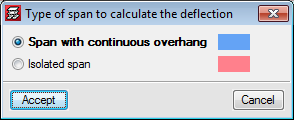
As of the 2017.a version, the program allows users to assign continuity to joists of the panels selected by users. In the “Type of span to calculate the deflection” (Slabs > “Joist continuity”) dialogue box, CYPECAD allows users to select two types of continuity for steel and timber joists:
- Span with continuous overhang
It is to be used for joist overhangs, so the joists have continuity. - Isolated span
This option is to be used to join two continuous panels, so the program treats the two joists as if it were a single element.
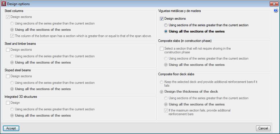
It is important to note that in the analysis of the panels with continuity, due to differences in stiffness, the results will not be the same if the analysis is carried out with the first section of the series or if the analysis begins with an intermediate section. Therefore, as occurs with the design of other steel and timber elements, an option has been added for steel and timber joists in the “Design options” dialogue box (which appears once the “Analyse” option has been selected when there are steel or timber elements present).