"BIMserver.center". BIM storage solutions for projects
BIMserver.center is a service managed by CYPE to save, synchronise and share BIM project files:
- Offers secure storage for BIM project files. All intervening agents can access it from any device and share them in a coordinated manner.
- Is a collaboration platform to centralise and manage all files in real time.
- An efficient and intelligent manner to optimise BIM workflow and communication amongst professionals.
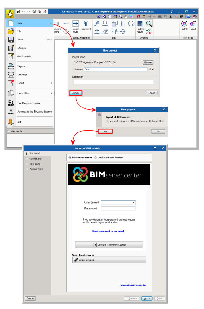
CYPE’s BIM programs (IFC Builder, StruBIM, CYPELUX, CYPETHERM...) can connect with this platform For example, when a new project is created from one of these programs, users can connect with BIMserver.center.
Timber joist floor slabs (CYPECAD module)
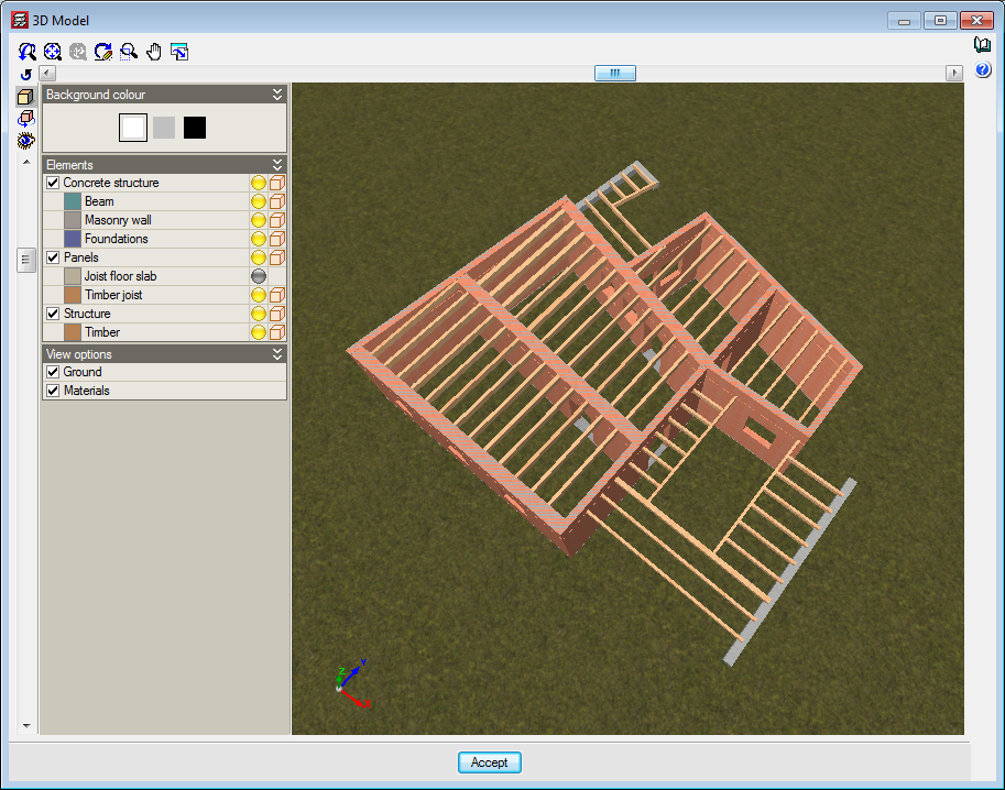
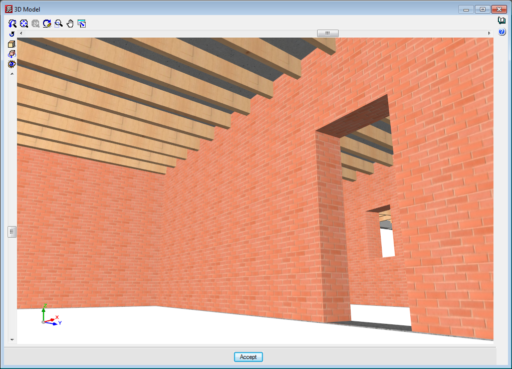
The “Timber joist floor slabs” module has been implemented in the 2017.a version, with which CYPECAD analyses and designs timber joist floor slabs.
A summarised description of this module can be found in the “Timber joist floor slabs” section of the new features of CYPECAD.
More information on the introduction, analysis and design of the timber joist floor slabs can be found on the “Timber joist floor slabs” webpage.
Timber sections (existing module that now designs timber beams in CYPECAD and CYPE 3D)
As of previous versions, users have been able to introduce “Generic” structural timber elements in integrated 3D structures in CYPECAD and CYPE 3D using the “Timber sections” module.
Further features have been added to the “Timber sections” module with the 2017.a version. Now, users can introduce beam-type timber elements in CYPECAD and CYPE 3D. By introducing the timber beams as that type of structural element instead of generic timber beams, allows specific beam checks to be carried out, and use the “Advanced beam editor” to edit and design these elements.
A summarised description of this new feature of the “Timber sections” module can be found in the “Timber beams” section of the new features of CYPECAD.
More information on the introduction, analysis and design of timber beams in CYPECAD and CYPE 3D can be found on the “Timber sections” webpage.
Timber joist floor slabs
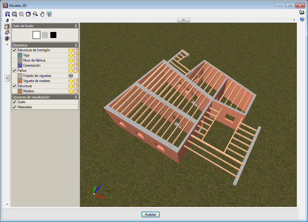
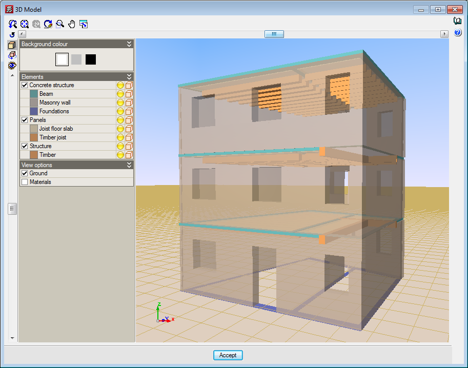
The “Timber joist floor slabs” module has been implemented in the 2017.a version, with which CYPECAD analyses and designs timber joist floor slabs.
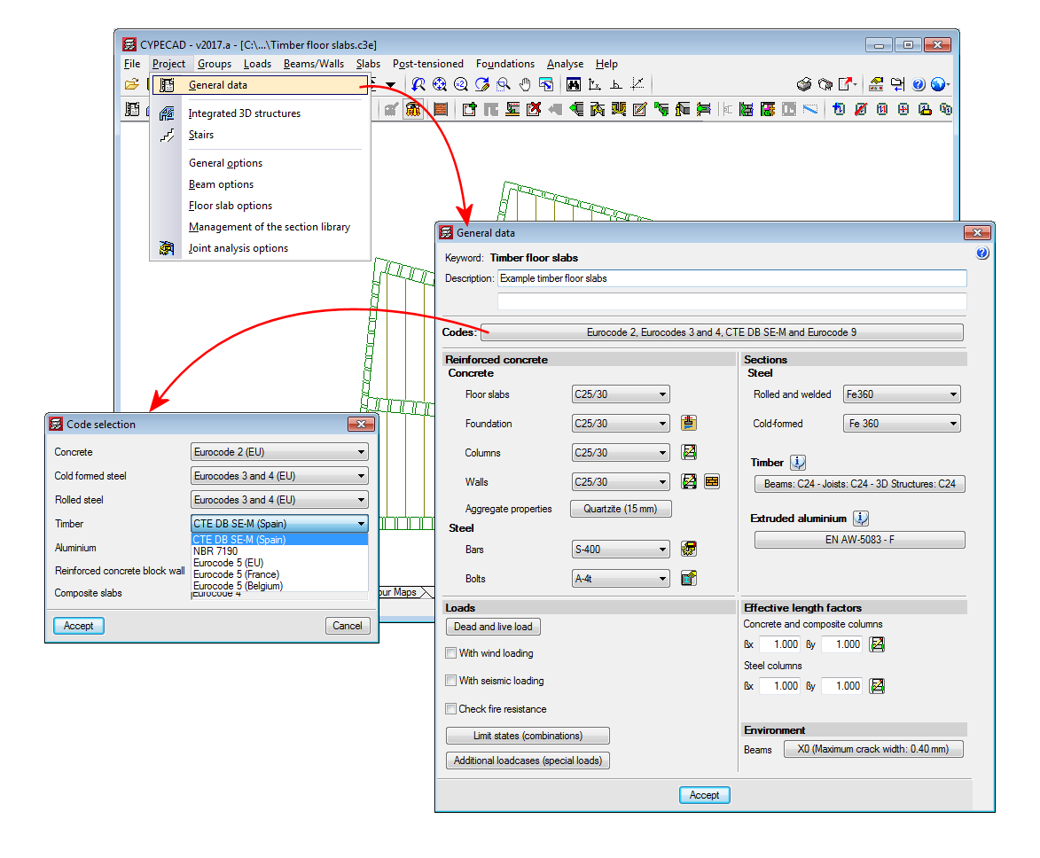
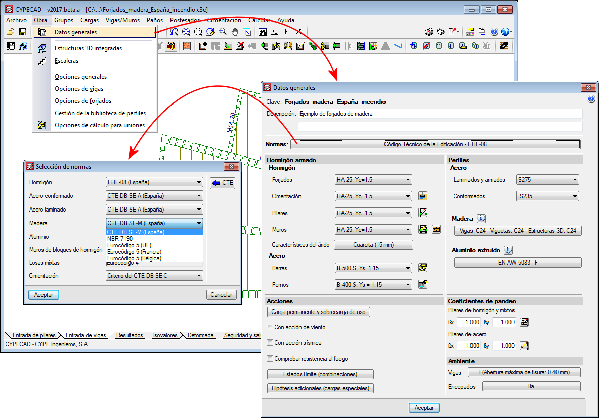
The codes implemented for the design and check of the timber joist floor slabs and beams are:
- CTE-DB -SE-M (Spain)
- Eurocode 5
- Eurocode 5 France
- Eurocode 5 Belgium
- NBR 7190:1997 (Brazil)
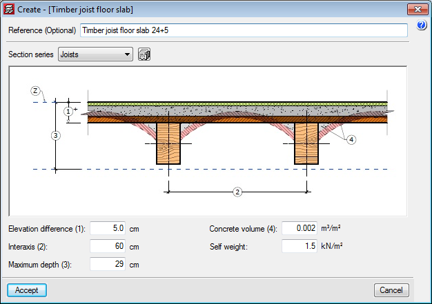
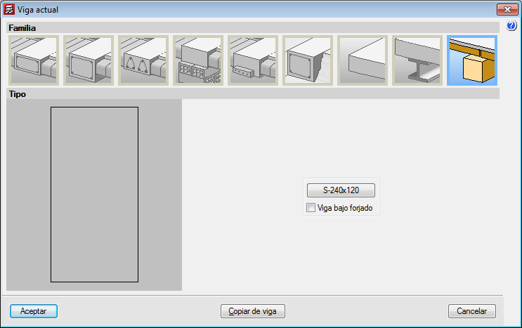
To adapt the program to the current market, timber sections have been created, distinguishing between sawn timber and laminated timber, and including the DUO/TRIO series, which are currently very much in use.
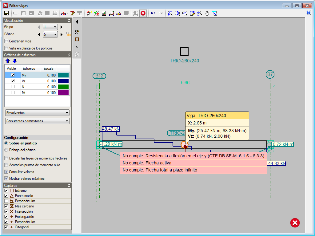
The sections that make up the timber joists are designed for simple bending, because due to the rigid diaphragm hypothesis, axial forces and forces in the plane of the floor slab are not considered.
The deflection checks for timber joists are obtained considering the deflection limits for the joist defined by users and the active deflection and long-term deflection.
CYPECAD also carries out a fire resistance check for timber beams using the “Fire resistance check” module.
For CYPECAD to be able to analyse and design joist floor slabs, the user licence must include, as well as CYPECAD, the “Timber joist floor slabs” and “Joist floor slabs (generic concrete beams)” modules. If, users also wish to check the fire resistance of these elements, they must also hold the “Fire resistance check” module permits.
More information on the introduction, analysis and design of timber joist floor slabs in CYPECAD can be found on the “Timber joist floor slabs” webpage.
Timber beams
Users can, as of previous versions, introduce generic-type structural timber elements in the integrated structures of CYPECAD and CYPE 3D using the “Timber sections” module.
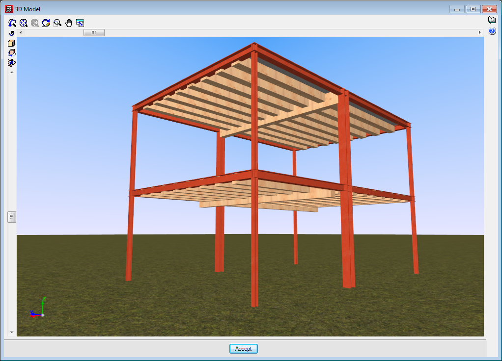
In the 2017.a version, the “Timber sections” module has further features and allows users to introduce beam-type structural timber elements in CYPECAD and CYPE 3D. By introducing the timber beams as that type of structural element instead of generic timber beams, allows specific beam checks to be carried out, and use the “Advanced beam editor” to edit and design these elements.
The codes implemented for the design and check of the timber joist floor slabs and beams are:
- CTE-DB -SE-M (Spain)
- Eurocode 5
- Eurocode 5 France
- Eurocode 5 Belgium
- NBR 7190:1997 (Brazil)
To adapt the program to the current market, timber sections have been created, distinguishing between sawn timber and laminated timber, and including the DUO/TRIO series, which are currently very much in use.
CYPECAD and CYPE 3D also carry out a fire resistance check for timber beams using the “Fire resistance check” module.
For CYPECAD and CYPE 3D to be able to analyse and design timber beams and generic timber bars, the user licence must include, as well as the permits corresponding to CYPECAD and/or CYPE 3D, the “Timber beams” module. If, users also wish to check the fire resistance of these elements, they must also hold the “Fire resistance check” module permits.
More information on the introduction, analysis and design of timber beams in CYPECAD and CYPE 3D can be found on the “Timber sections” webpage.
Steel joist checks
Resistance checks
Ultimate limit state and serviceability limit state check reports for steel joists have been implemented in the program. The option: Check (steel and timber) has been included in the “Joists” menu in the “Results” tab, which allows users to obtain the ultimate limit state and serviceability limit state checks of each joist. This option is also used to obtain the check reports of timber joists, also implemented in the 2017.a version.
Fire checks
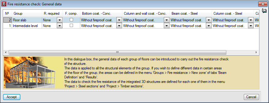
The 2017.a version of CYPECAD includes a fire resistance check for steel joists. The data definition for the fire resistance check of steel joists in CYPECAD is the same as for steel beams in the “Fire resistance check” dialogue in the “General data” option (Project > General data > Loads > Fire resistance check). As occurs with other structural elements of CYPEAD, the required resistance and cladding (if present) for each type of structural element is defined for each floor group.
Different data can be defined in any zone of a floor group using the options in the Fire resistance floating window (Groups > Fire resistance from the Beam Definition or Results tab).
CYPECAD will carry out each resistance check at room temperature (persistent or transitory situation) and in the case of a fire, in accordance with the specifications of the code.
Continuity of joists (steel and timber)
The joists of adjacent panel can now be assigned as being continuous, for steel and timber joists. This way, the program will design each continuous joist of both panels as if it were a single element.
In previous versions, when steel joists (and now timber joists) were introduced, the panel were designed independently, and the joists were assumed to be simply supported, except in the case of overhangs, where they were automatically fixed in order to maintain equilibrium. In this case, if the joists have a design error, the program will indicate that it is not possible to design the joist as a continuous element.
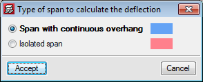
As of the 2017.a version, the program allows users to assign continuity to joists of the panels selected by users. In the “Type of span to calculate the deflection” (Slabs > “Joist continuity”) dialogue box, CYPECAD allows users to select two types of continuity for steel and timber joists:
- Span with continuous overhang
It is to be used for joist overhangs, so the joists have continuity. - Isolated span
This option is to be used to join two continuous panels, so the program treats the two joists as if it were a single element.
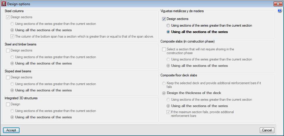
It is important to note that in the analysis of the panels with continuity, due to differences in stiffness, the results will not be the same if the analysis is carried out with the first section of the series or if the analysis begins with an intermediate section. Therefore, as occurs with the design of other steel and timber elements, an option has been added for steel and timber joists in the “Design options” dialogue box (which appears once the “Analyse” option has been selected when there are steel or timber elements present).
Earthquake resistance category of beams
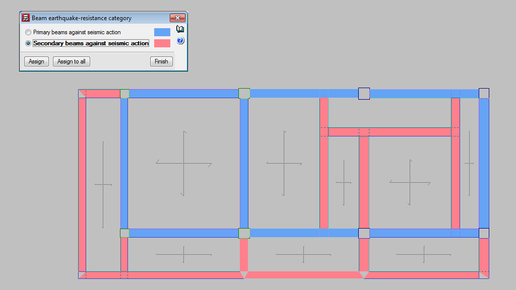
In the seismic analysis of the structure, CYPECAD can design structural beams as primary or secondary beams, depending on their role in the earthquake-resistant structure (Beam Definition > Beams/Walls > Secondary beams). Secondary beams are not considered as being part of the structural system to resist seismic loads hence, these elements do not need to be designed specifically for that.
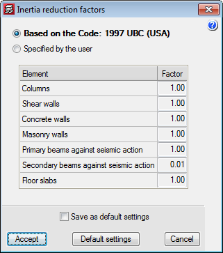
The stiffness of the secondary beams, for seismic loadcases, is reduced depending on the value defined in the “Inertia reduction factors” dialogue box (“Project” > “General options”). The mass of the secondary beams is taken into account.
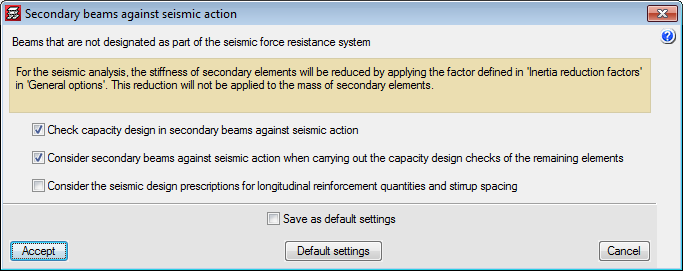
As for the capacity checks, users can indicate how the secondary beams are to be considered depending on their judgement. The following options can be activated in the “Secondary beams against seismic action” dialogue box (“Project” > “General data” > “Design options for steel bars” > “Beam options” “Design/Code check”):
- Check capacity design in secondary beams against seismic action.
- Consider secondary beams against seismic action when carrying out the capacity design checks of the remaining elements.
- Consider seismic design prescriptions for longitudinal reinforcement quantities and stirrup spacing.
Partial fixity coefficient at beam ends
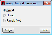
In the 2017.a version of CYPECAD, users can introduce a partial fixity coefficient at the end of a concrete beam. To do so, the option: “Fixity at beam end” (Beam Definition tab > “Beams/Walls”) has been implemented, which opens a dialogue box in which users can indicate that the beam end is:
- Fixed (default option)
- Pinned
- Partially fixed
Users can introduce a numerical value between “0” (pinned) and “1” (fixed).
When this option is selected, symbols are drawn, in a different colours and shapes, at the ends of the beams to indicate which option has been applied.
In previous versions, beam ends could be pinned or fixed using the “Pin/Disconnect” option which is also used to disconnect columns from wall-support type beams. Now this option is only used to disconnect columns and is now called “Disconnect/Connect”.
Selection of frames to be displayed in beam drawings
In the 2017.a version, users can select the frames of each group to be represented in the “Frames drawing”. To do so, an option: “Selection in groups” has been implemented in the “Frames drawing” configuration dialogue (File > Drawings > Add or edit the “Frames drawing”). Upon selecting this option, a button is displayed indicating the number of selected frames that are going to be represented in the drawing (which by default , are all the frames of the project). By pressing this button, a dialogue box appears where users can select which frames from which floors are to be shown on the drawings.
Shaded force envelope diagrams of beams
With the 2017.a version, shaded force diagrams of beams and joists can be displayed (with a different colour depending on the type of force). To do so, a new option “Draw the diagrams with infill” has been included in the “Forces in beams” and “Forces in joist” dialogue boxes (Results > Envelopes > “Forces in beams” or “Forces in joist”).
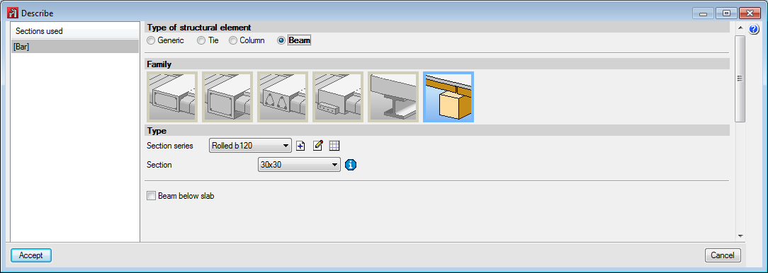
Timber beams
Users can, as of previous versions, introduce generic-type structural timber elements in the integrated 3D structures of CYPECAD and in CYPE 3D using the “Timber sections” module.
In the 2017.a version, further features are added to the “Timber sections” module and now users can introduce beam-type structural timber elements in CYPECAD and in CYPE 3D. By introducing the timber beams as that type of structural element instead of generic timber beams, allows specific beam checks to be carried out, and use the “Advanced beam editor” to edit and design these elements.
More information on the new features of the “Timber sections” module, applicable to CYPECAD and CYPE 3D, can be found in the Timber beams section of the new features of CYPECAD on this webpage.
Calculation of forces in shell integration strips
Once CYPE 3D has analysed a shell, “Integration strips” are generated in the two-dimensional element to process the nodal solutions provided by the finite element method and calculate the resultant force at specific sections of interest for the analysis.
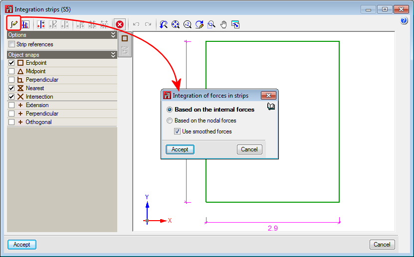
As of the 2017.a version, the resultant can be calculated by applying one of the following methods:
- Internal forces integration method
The internal forces method is based on integrating the forces of the shell (forces per linear unit) calculated at certain points of the analysis section, determined by the program. The forces at each point are obtained by interpolating the corresponding nodal values of the element to which they belong. Once the forces are known at the points of the section, they are integrated to obtain its acting resultant.
The program offers the possibility to “Use smoothed forces”. The smoothing of forces consists in averaging the value at a vertex based on the values of each triangle that converge towards it. For the force interpolation process, the value at the vertices of the elements can be the actual value of each triangle, or the averaged value, depending on whether this option is selected or not.
This method provides very good results with a reduced integration strip width. - Nodal forces integration method
The nodal forces integration method calculates the resultant in a section of the shell using the forces at the nodes of the triangles. These are obtained by multiplying the stiffness matrix of the element by its displacement vector. Once the nodal forces are known, a part or portion of the shell in, where one of its edges is the analysis section, is isolated. The resultant in this section is obtained by reaching equilibrium of all the forces acting on the element: forces in the nodes of the perimeter and forces on the isolated portion.
This method provides very good results when the integration strip to calculate the resultant, has the entire width of the strip. When the width of the strip is smaller and this method is being used, it is recommended a refined discretisation of the shell be used or, alternatively, the method described previously: “Internal forces integration method”.
Thanks to the implementation of this option for CYPE 3D, StruBIM design allows users to select either method to integrate the forces in slabs and walls. More information on which method should be applied depending on the element whose forces are going to be obtained, can be found in the section: “Preferential methods for force integrations in 2D elements” in the new features of “StruBIM Design”.
StruBIM Analysis 3D and StruBIM Design are no longer BETA versions
As of the 2017.a version, StruBIM Analysis 3D and StruBIM Design are no longer BETA versions and are completely operational.
Preferential methods for force integrations in 2D elements
To design and check floor slabs and walls, StruBIM Design processes the results from their analysis based on the finite element method. This analysis provides solutions at specific points of the 2D structure, depending on the established discretisation. Based on these solutions, the design values required for the design and reinforcement are obtained by generating integration strips in the two-dimensional element and the calculation of the resultant in the corresponding design section.
As of the 2017.a version, StruBIM Design offers users the possibility to calculate this resultant by applying the “Internal forces integration method” or “Nodal forces integration method”.
Evaluation of the integration methods
The first premise is to have the internal and/or nodal forces in the 2D elements considered, to be able to apply one method or another. Depending on the origin of the analytical model which is being worked on (xml, sbar, etc.), the available design data may vary. Obviously, when only one of the types of data is available, only the corresponding method can be applied. If both the internal forces and nodal forces are available, it is the user’s choice which method is most adequate. The following observations on the methods can be used to guide users as to which method they should apply:
- Integration of nodal forces
The nodal forces integration method provides very good results when the width of the integration strip to calculate the resultant, is the entire width of the 2D element, regardless of the discretisation size used, as occurs when treating walls in StruBIM Design. When the width is smaller, and this method is being applied, it is recommended a more reined discretisation of the two-dimensional element be used. - Integration of internal forces
The internal forces integration method provides very good results when the integration strip width is small, as occurs when calculating the required slab reinforcement in StruBIM Design.
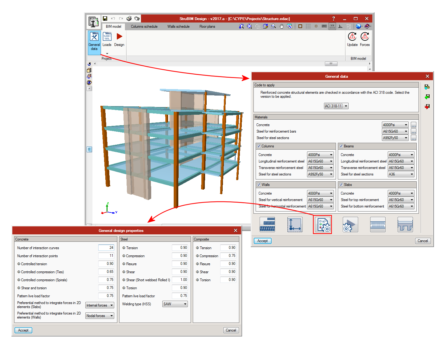
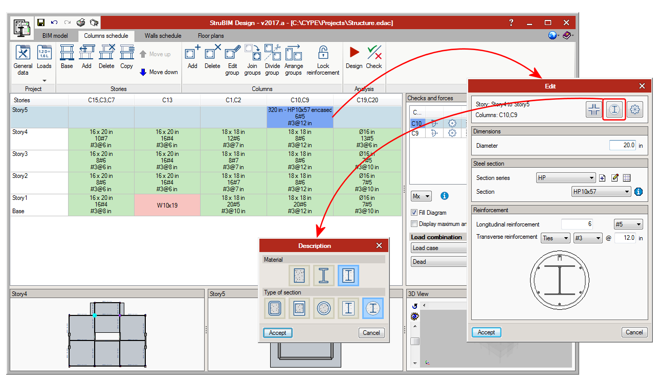
Concrete and steel composite columns
The 2017.a version of StruBIM Design includes the definition and check of concrete and steel composite columns. These are checked in accordance with the ANSI/AISC 360-10 code.
The types of composite columns the 2017.a version of StruBIM Design can check are:
- Rectangular tube filled with concrete
- Welded rolled-steel plates rectangular box, filled with concrete
- Circular tube filled with concrete
- Rectangular concrete section with encased steel section
Rectangular concrete section with longitudinal and transverse reinforcement and encased I-section. - Circular concrete section with encased steel section
Circular concrete section with longitudinal and transverse reinforcement and encased I-section. Stirrups or spirals can be used as transverse reinforcement.
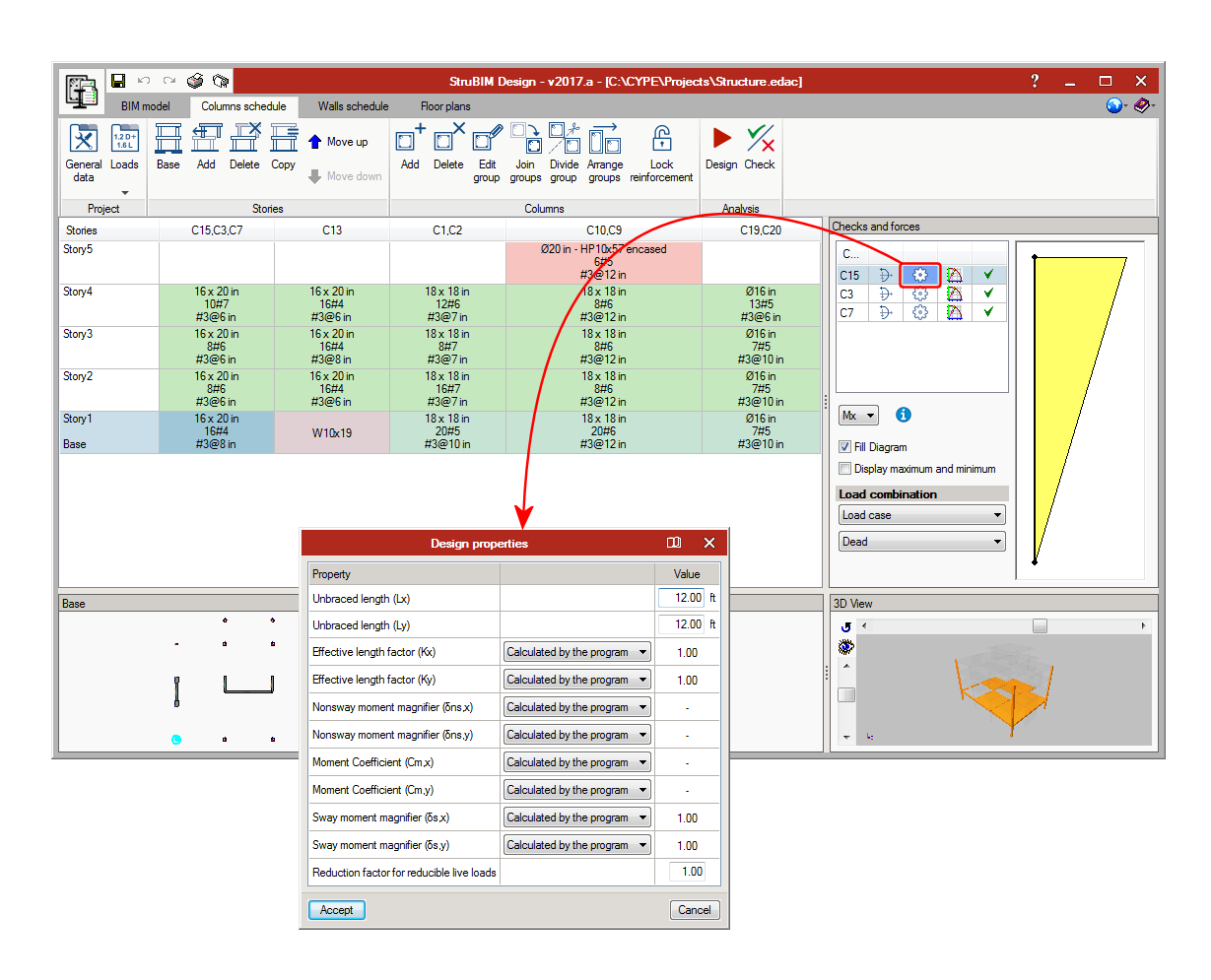
Column design properties
As well as the existing design properties of previous versions, the 2017.a version implements options to edit the following properties:
- Sway moment magnifier (s in ACI 318)
This factor amplifies moments for wind and seismic nature loadcases in concrete columns. - Reduction factor for reducible live loads
Forces belonging to loadcases with “Reducible live load” nature are multiplied by this coefficient. - Unbraced length for buckling due to bending
- Unbraced length for buckling due to torsion
- Effective length factor
- Non-sway moment magnifier (B1, ANSI/AISC 360-10)
- Non-sway moment magnifier (B2, ANSI/AISC 360-10)
This factor amplifies moments for wind and seismic nature loadcases in steel columns.
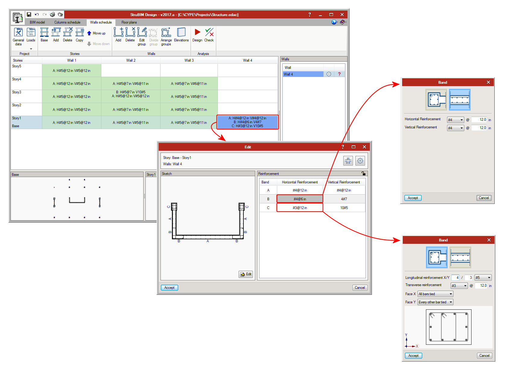
Confinement reinforcement in concrete walls
As of the 2017.a version, users can select between two types of reinforcement for wall spans: “Reinforcement by faces” (this is the type in previous versions) and “Confinement reinforcement” (new type). This new type allows for typical reinforcement to be defined at wall ends.
A shear wall can be composed of several spans with the same or different thickness. Each span of the wall can be assigned different reinforcement strips, for their composition or type.
- Reinforcement by faces
A bar diameter is defined as well as the horizontal and vertical reinforcement spacing, which will be the same for either side of the wall. - Confinement reinforcement
The number of longitudinal bars per side of the wall and their diameter is defined, as well as the transverse reinforcement composed of closed stirrups and intermediate cross-ties (column-type).
The program designs and checks the reinforcement depending on the selected type.
Punching shear check
As of the 2017.a version, StruBIM Design carries out a punching shear check on floor slabs supported by columns. The program automatically generates the critical section for each column that transmits forces to the floor slab and allows for it to be edited. StruBIM Design verifies, for the critical perimeter, if the resistance against tangential stress is exceeded in floor slabs without shear reinforcement, which resist bending in both directions. Additionally, users can now introduce shear reinforcement in floor slabs and check critical sections with reinforcement.
The program allows users to introduce shear reinforcement as stirrups or shear studs and verifies the resistance at the perimeters at either side of the reinforcement. Furthermore, StruBIM Design checks the geometric layout and reinforcement in accordance with the design code.
The layout of the column can be modified (centre, edge or corner), as can the effective depth of the floor slab, the maximum and minimum width of the support, and the critical perimeter of the support and reinforcement (taking into account openings and edges, indicating the effective segments against punching shear). It is also possible to modify the reinforcement data of stirrups and shear studs.
The forces at the top and bottom of each support can be consulted. The difference between these forces corresponds to the punching shear forces transmitted to the floor slab at that floor.
Punching shear of columns close to each other, with their internal and external perimeters together, can be checked and their perimeters edited.
Steel beams
The 2017.a version includes the design and check of steel beams in accordance with the requirements of the ANSI/AISC 360-10 code.
The types that have been implemented are:
- I-section
- Circular hollow section
- Rectangular hollow section
- Rectangular reinforced box