
General information
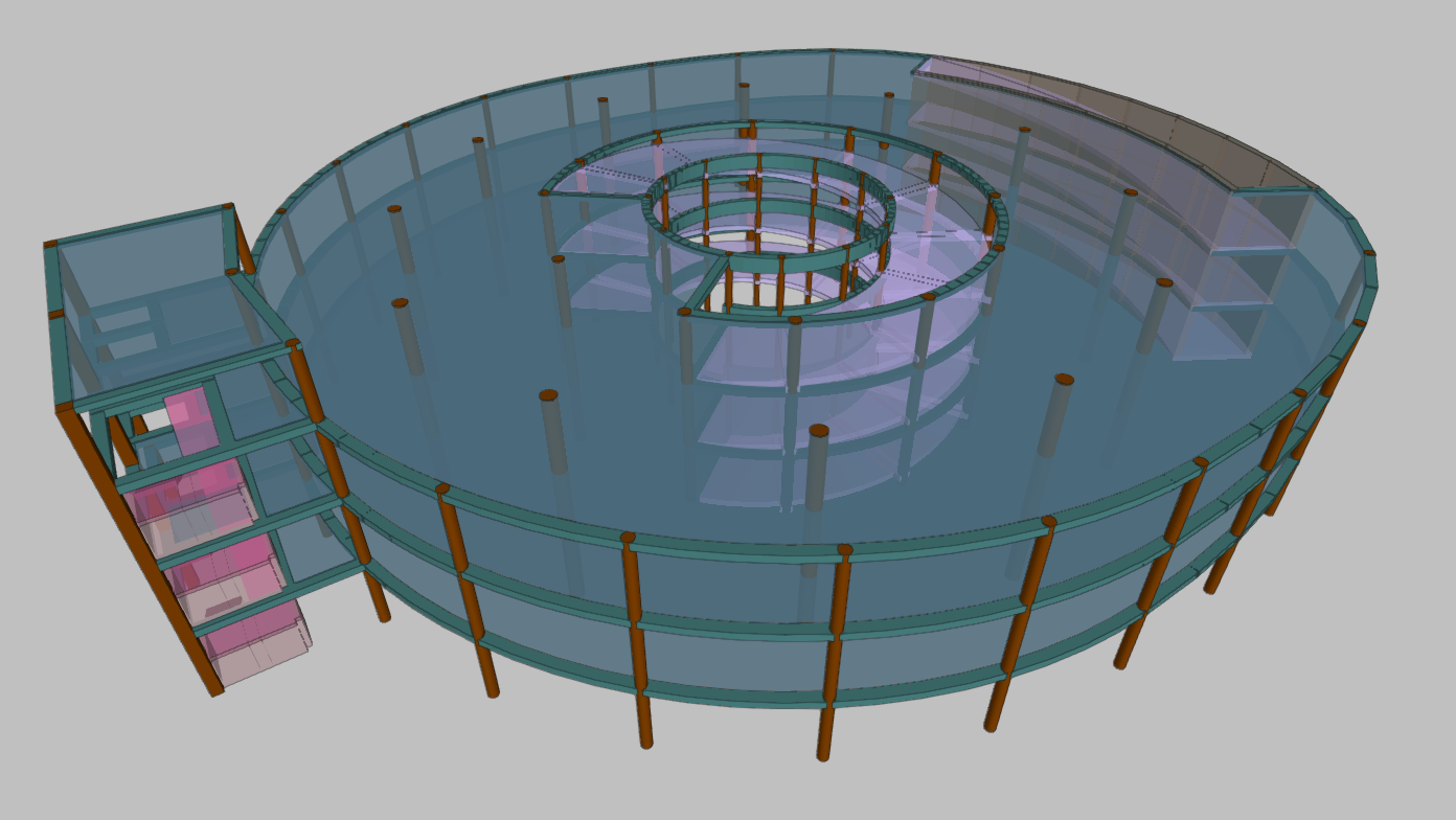
The new CYPECAD ramp module analyses and designs slabs for ramps as isolated elements of the structure. Depending on the geometry, type and layout of the supports and applied gravity loads, the program determines the reactions and applies them as loads on the main structure, resulting in linear loads in the loadcases of dead loads and live loads.
The program resolves ramp cores formed by spans arranged between floors. Each span is made up of one or several elements of one of the types listed below:
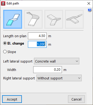
- Straight flight
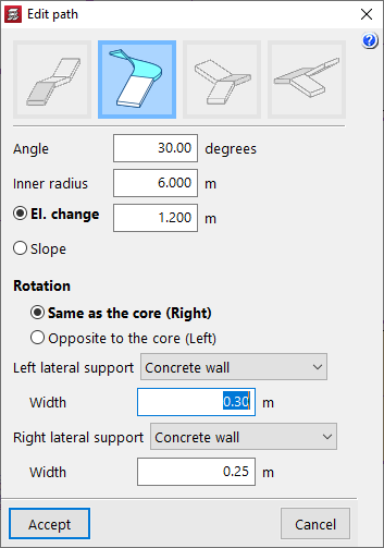
- Curved flight
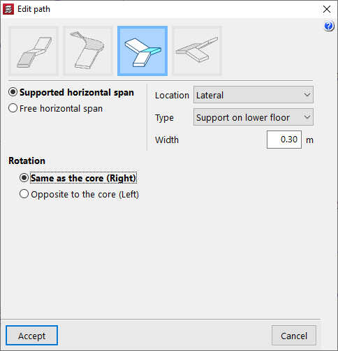
- Horizontal span - Quarter turn
- Horizontal span - Half turn
Defining ramp cores
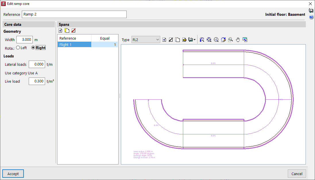
A ramp core is defined by indicating the data common to the core (width, rotation direction, loads) and the particular data of each span.
Ramp spans are fractions of the ramp core that run from one floor to the next. Each span is made up of a succession of straight or curved spans and, optionally, half-turn and quarter-turn intermediate horizontal spans.
Straight flight
Curved flight
Horizontal span - Quarter turn
Horizontal span - Half turn

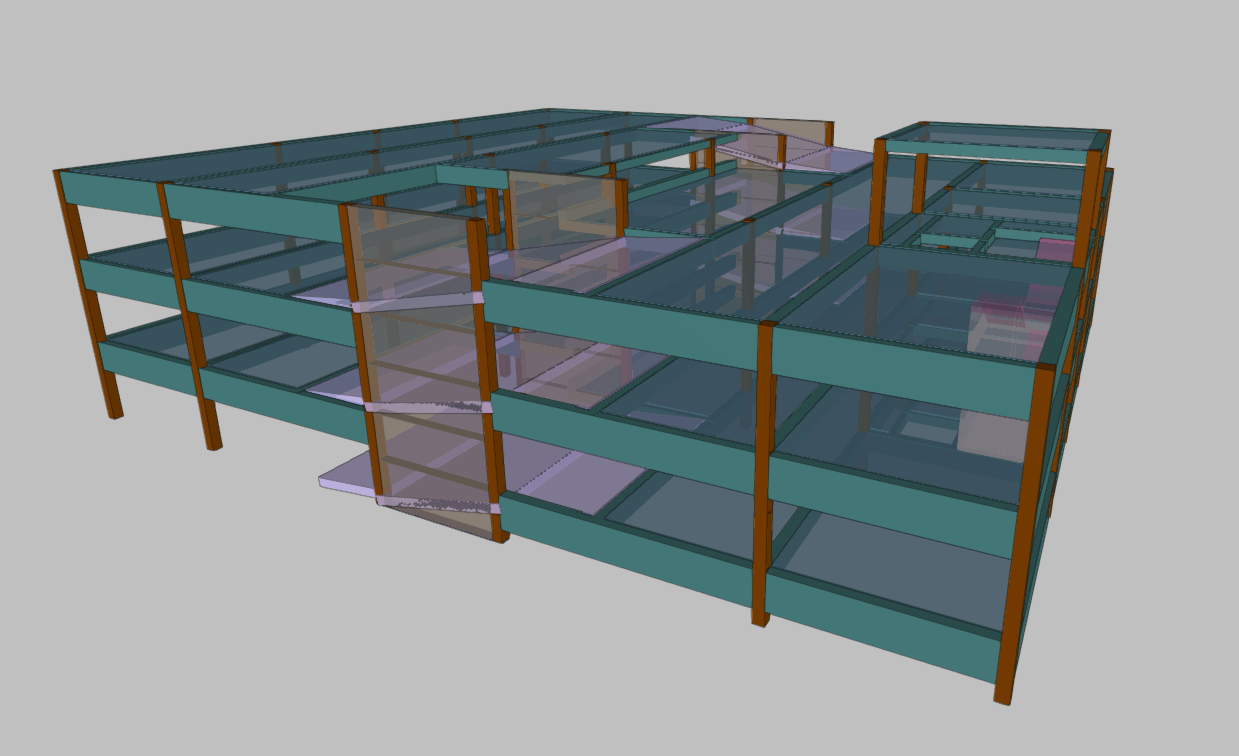
Placing in the structure
The start of the first span and a crossing point of the axis of its first run must be specified in order to place the ramp core in the structure. CYPECAD will enter the core with all the spans on the corresponding floors. To help locate these two points, DXF or DWG snaps can be used.
Analysis, results, reports and drawings
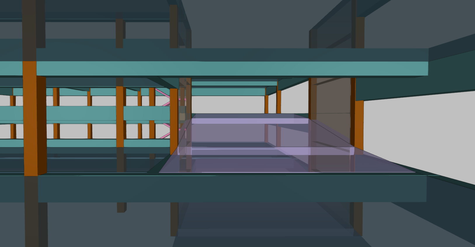
The program analyses the ramps separately and using the finite element method, considering the two load cases of dead loads (self-weight and dead loads) and live loads.
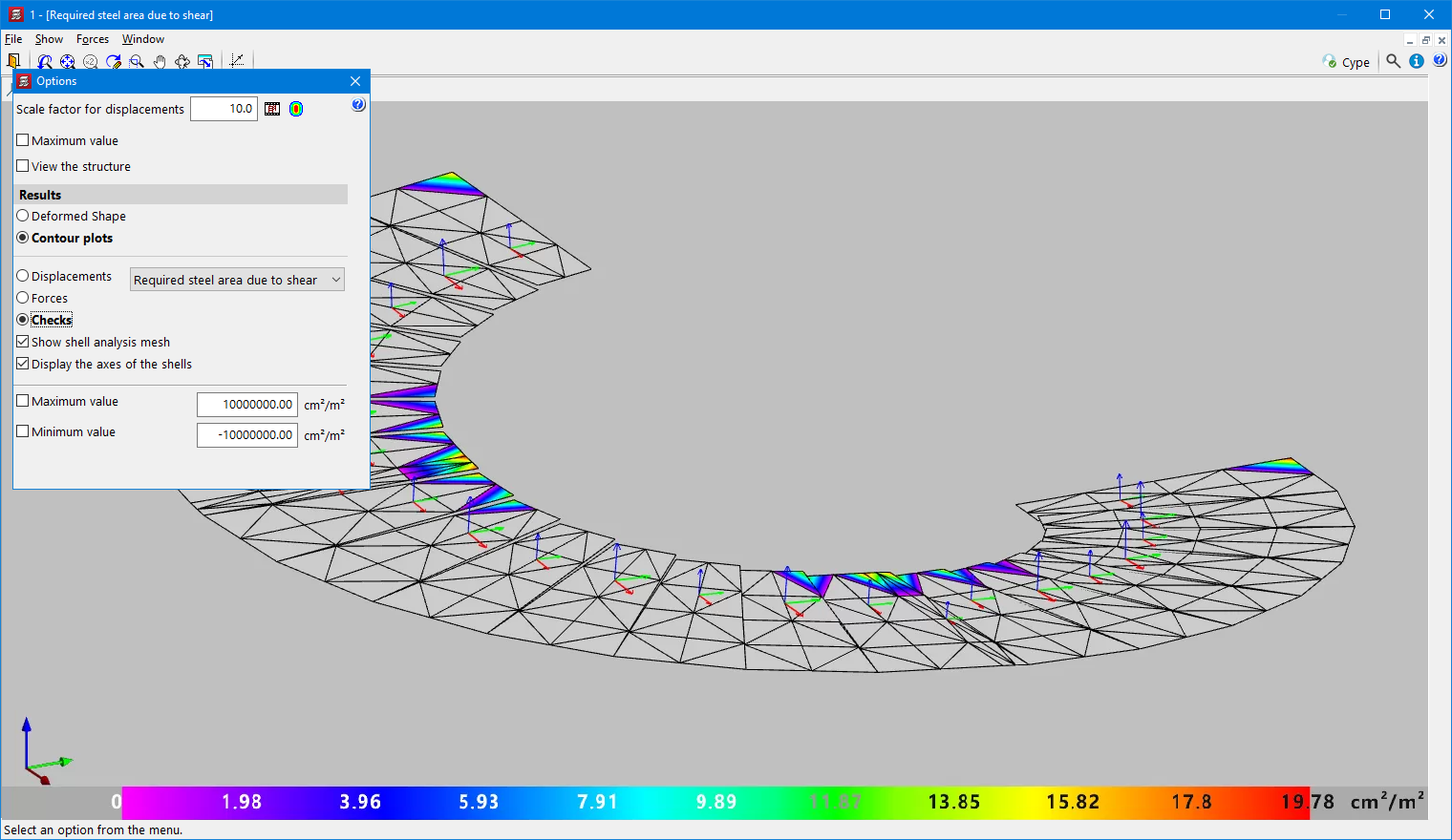
CYPECAD displays the reinforcement of each of the spans making up the ramp core on screen. Users can also consult the contour plots of displacements and forces in a 3D view, including the total shear, as well as visualise the deformed shape of each span.
Considering the shear strength criteria of the selected concrete code, the need for shear reinforcement in some areas and the required ratio is determined. If shear reinforcement is required at any point of a ramp, a warning is displayed. The ratio can be found in the "Forces and displacements - Contour plots - Checks" option.
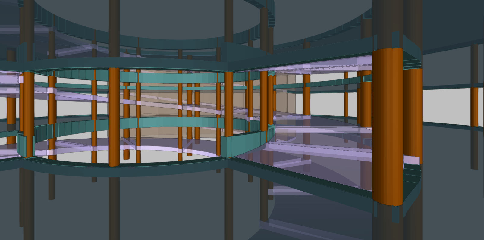
When the job is analysed, all ramp cores are also analysed and their reactions are applied to the main structure as loads.
Each ramp core can also be analysed individually. To do this, the program only needs to be prompted to display the reinforcement, forces and displacements of the ramps. If the job has not been analysed or if changes have been made since the last analysis, only the selected core will be analysed.
The program provides a warning if changes are made to a ramp core after the job has been analysed, as these changes affect the value of the reactions. In this case, the job must be re-analysed in order to take the new reactions into account.
A report of the ramps with general information about the job and specific information for each core can be obtained, including the results obtained for the forces and reinforcements of each span.
The drawings show all the information required for the ramp reinforcements to be defined: longitudinal and transverse sections, tables of characteristics of each span with their geometric data, loads and materials. The reinforcement quantities tables are also included (by cores, spans and total steel summaries).
Configuring the ramp module (materials, reinforcement tables and analysis options)
The concrete used in the ramp cores is the same as the one selected for the floor slabs. The type of steel used in their reinforcement, on the other hand, can be specified separately. The program has two reinforcement tables (longitudinal and transverse) and a series of analysis options for ramps, which can be configured to suit personal preferences.