The 2015.d version of CYPE 3D allows users to define shells. Shells are flat two-dimensional elements with constant thickness and without openings, whose perimeter is defined by a polygon.
Shells are introduced in the global stiffness matrix of the structure using a three-dimensional finite element model composed of six-node (quadratic) triangular flat shells. The type of element used is based on the overlap of two locally decoupled elements: one provides the axial stiffness (membrane forces) and the other the bending stiffness (panel forces).
The following properties can be defined for each shell:
- Thickness and subgrade modulus
In the local Z axis direction - Material
Concrete, rolled steel, cold-formed steel, aluminium and generic material (by specifying the modulus of elasticity and Poisson coefficient). - Position
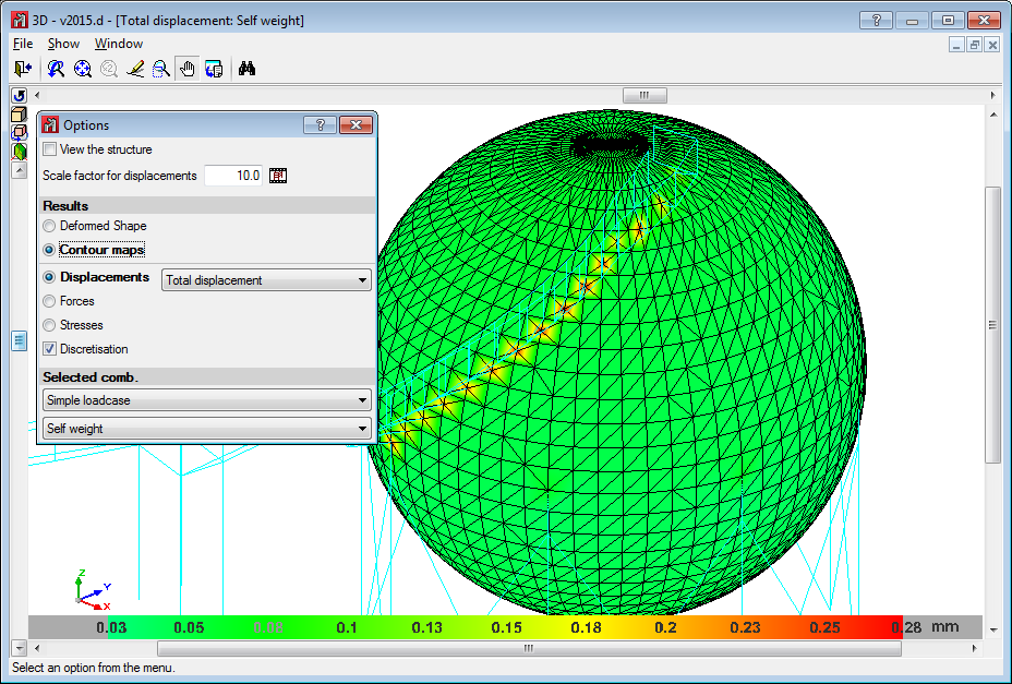
With respect to the introduction plane - Discretisation
The density of the mesh can be controlled by defining the maximum size of the triangle in the local x and y axes. - Direction of the axes
- Internal fixity
Internal fixity between the edges and other elements of the structure. - External fixity
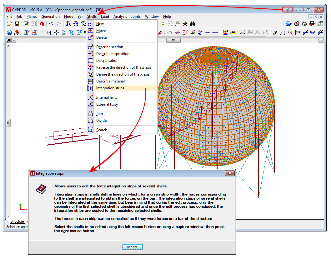
It is also possible to define the external fixity of the edges, but in this case, the fixity is applied to all the shells sharing that edge. The possible external fixity configurations are the same as those available for the nodes of CYPE 3D. - Integration strips
Integration strips in shells define lines on which, for a given strip width, the forces corresponding to the shell are integrated to obtain the bar forces.
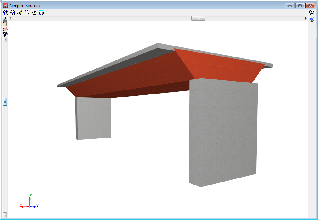
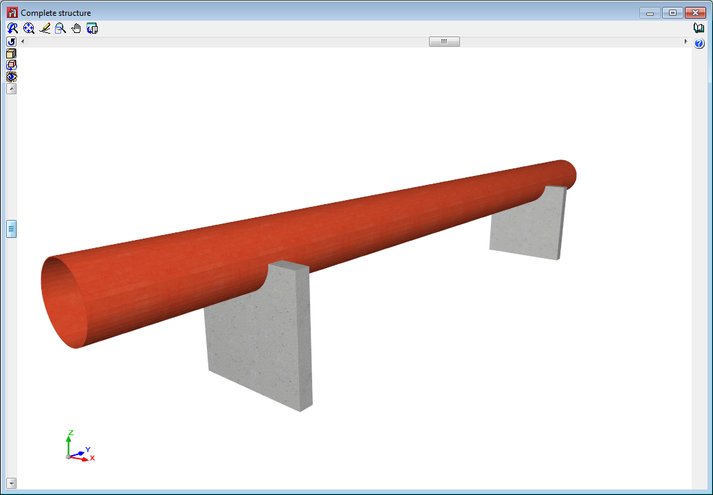
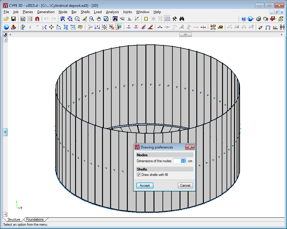
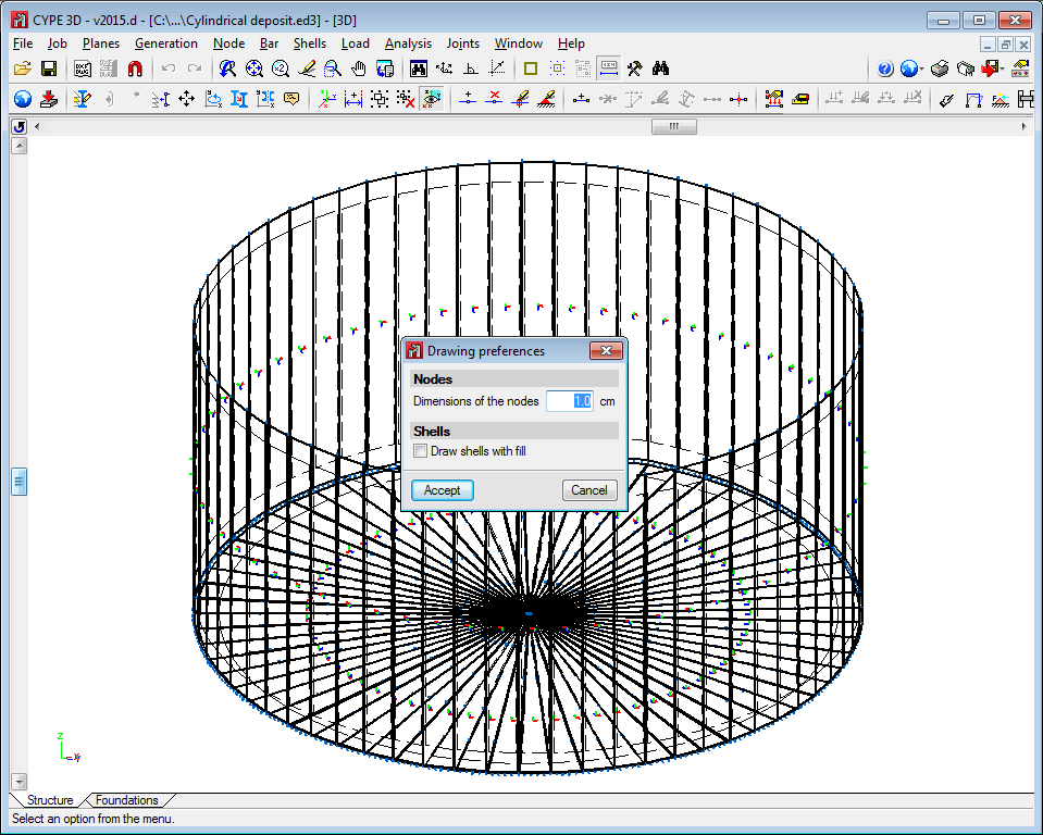
The program contains an option which users can use to view the shells in 3D. They can be viewed filled in or simply their outline can be displayed. This can be indicated in the drawing preferences option in the Job menu.
To be able to use shells in CYPE 3D, users must have the permits required to use CYPE 3D.
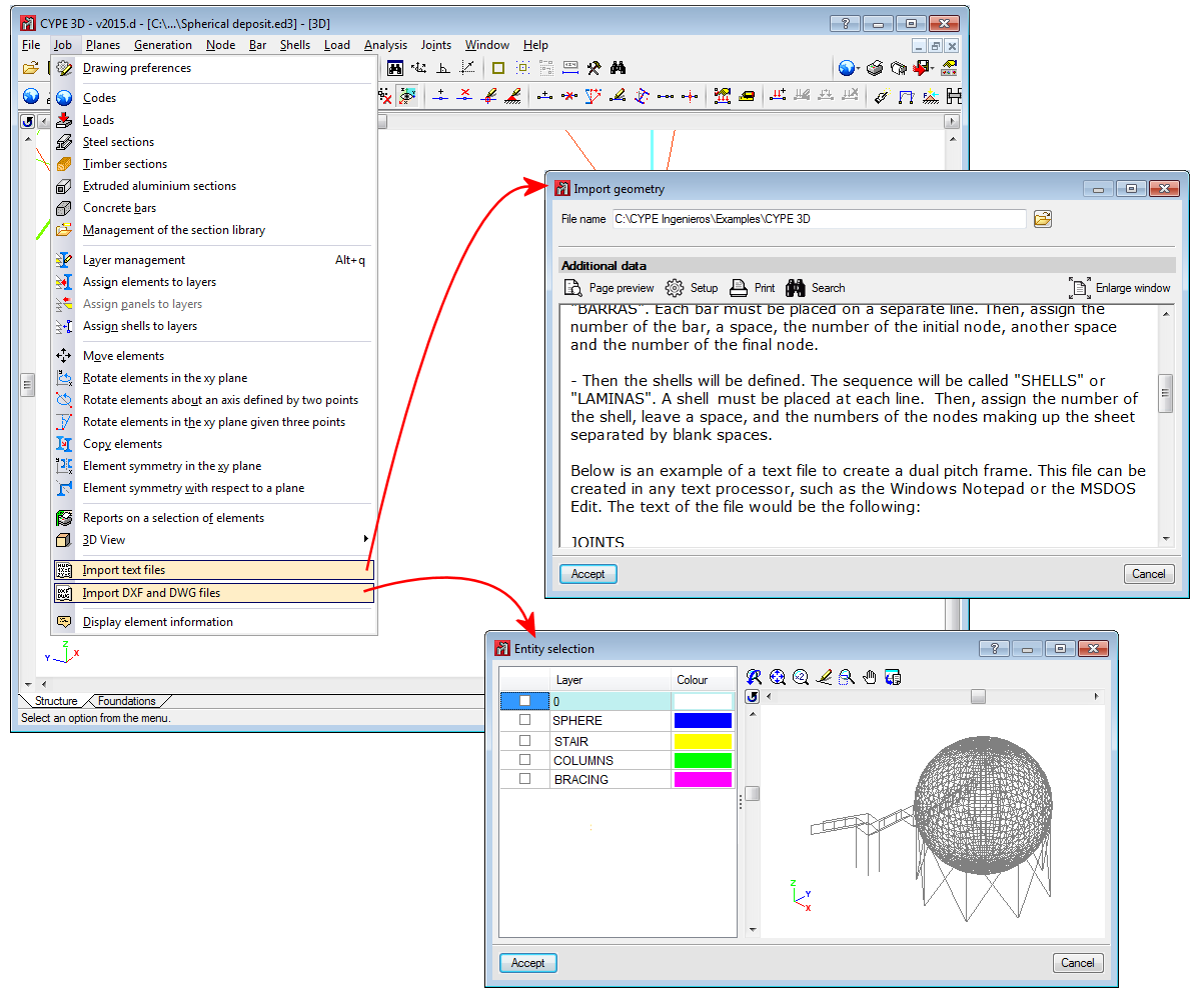
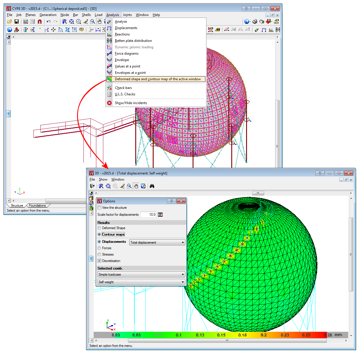
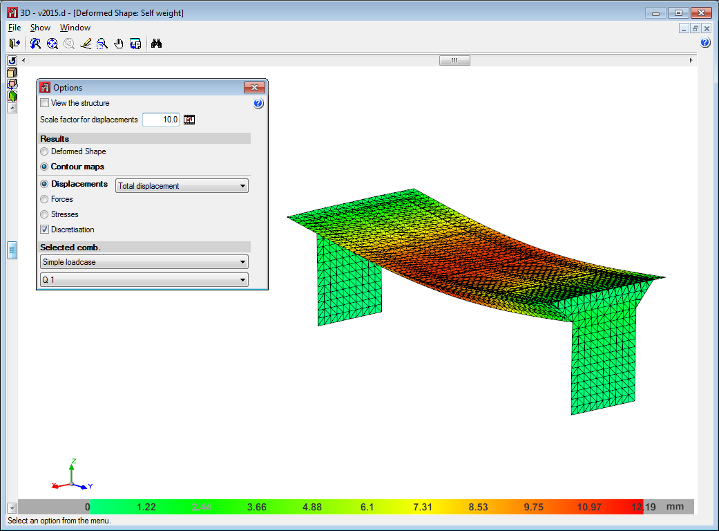
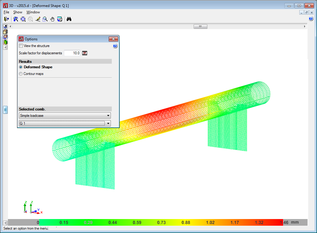
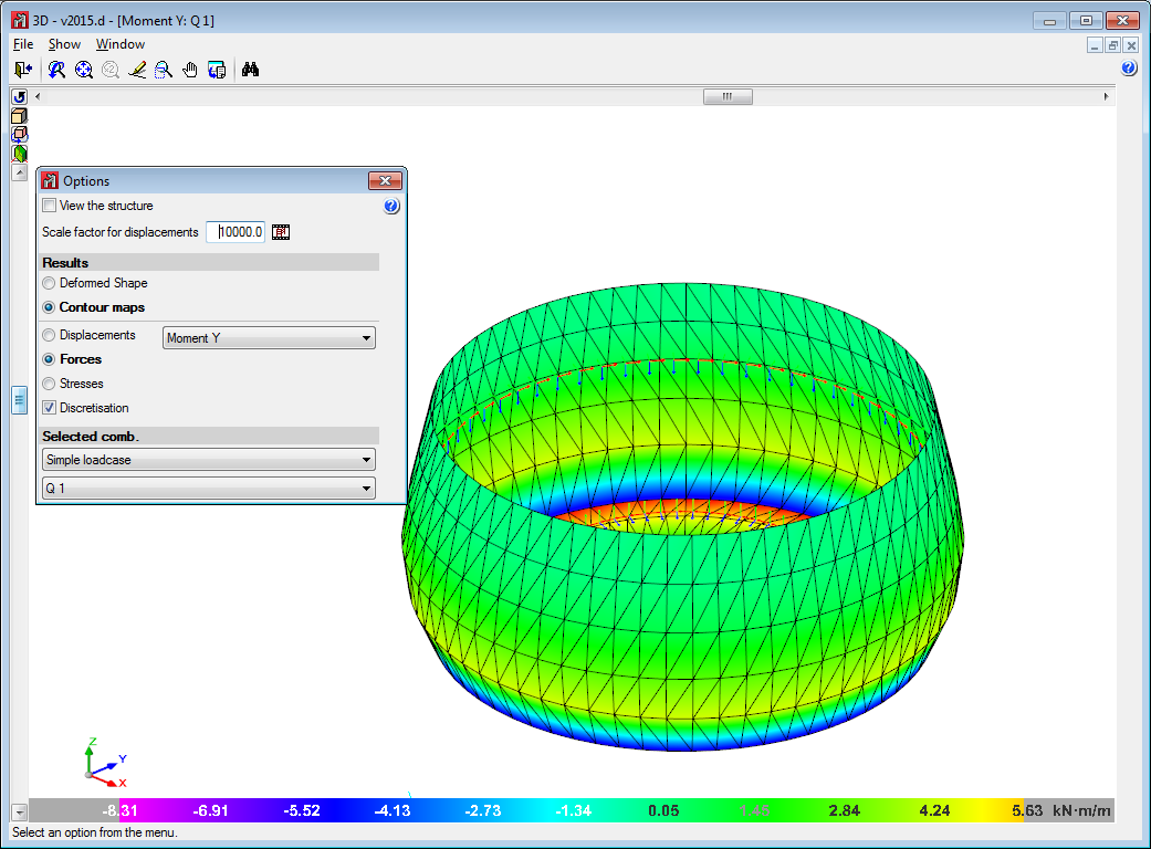
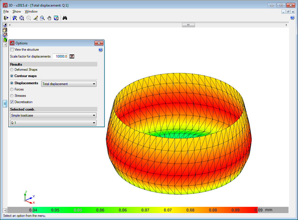
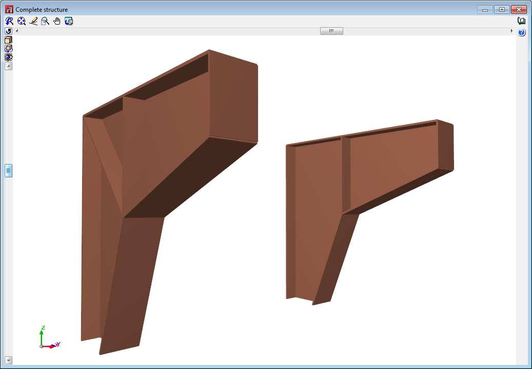
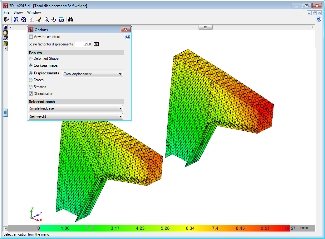
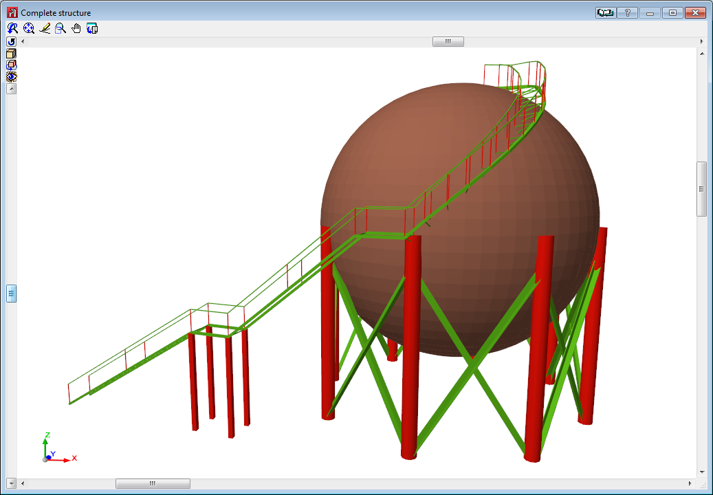
Below are some examples of structures created with shells in CYPE 3D: