Options in the "Foundation" tab
The lower tab "Foundation" contains the tools for the design and calculation of the foundation elements. The upper ribbon includes:
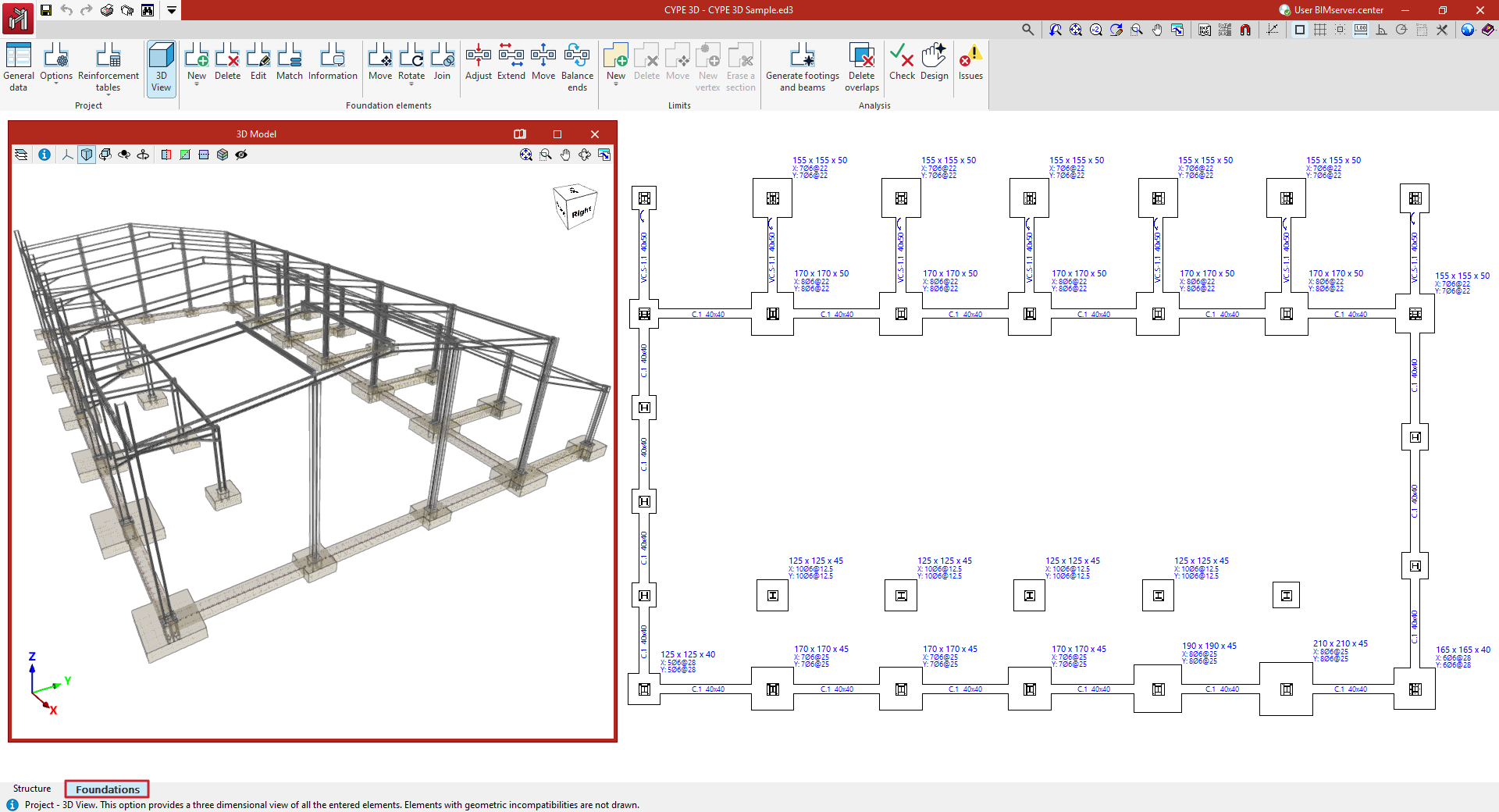
- in the "Job" group, the options for configuring the general data of the foundation, its analysis and design options, and the reinforcement tables, as well as for obtaining the 3D view;
- in the "Foundation elements" group, the options for entering the foundation elements (footings, pile caps, tie beams and centring beams), as well as options for editing and adjusting them;
- in the "Limits" group, the options for entering and managing footing polygonal limits;
- and in the "Analysis" group, the options for the automatic generation of footings and beams, and for the analysis, checking and design of foundation elements, as well as for the display of events.
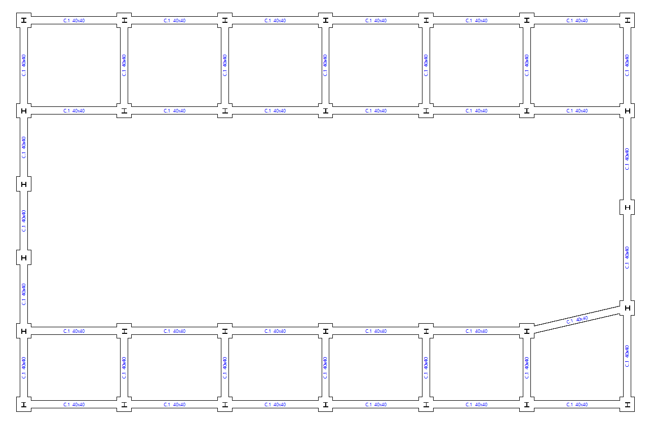
The display of this tab shows the starts of the vertical bars entered in the "Structure" tab, which have an external fixity defined at their base with fixed displacements.
Entering foundation elements
New foundation elements can be added to the model using the "New" tool in the "Foundation elements" group in the lower "Foundation" tab.

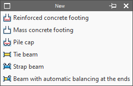
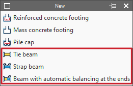
New
Enters a new foundation element in the model. This menu offers the following options:
- Reinforced concrete footing
- Mass concrete footing
- Pile cap
- Tie beam
- Strap beam
- Beam with automatic balancing at the ends
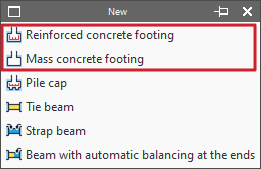
Entering footings
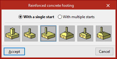
Footings are entered using the first two options in the "New" menu of the "Foundation elements" group, in the "Foundations" tab: "Reinforced concrete footing" and "Mass concrete footing" (without reinforcement by default).
In either of the two cases, in the pop-up window that appears, you must choose "With a single start" if it is an isolated footing or "With multiple starts" in the case of a combined footing or a footing common to several columns.
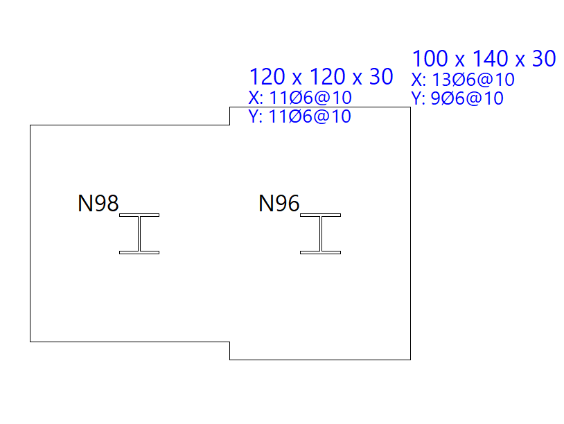
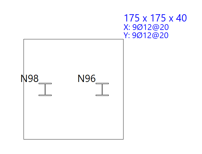
You must also indicate whether it is a square, rectangular or pyramidal footing, and whether it is centred or eccentric by choosing the corresponding type:
- Square footing
- Centred rectangular footing
- Eccentric rectangular footing
- Tapered square footing
- Tapered centred rectangular footing
- Tapered eccentric rectangular footing
Footings with a single start (pad footings)
In this case, after clicking "Accept", the footing must be placed on the ground plan. If the mouse pointer is placed over a foundation, it takes the form of two concentric squares. If you click at this point, the foundation element will be positioned centrally under the support.
If you have chosen an eccentric footing, you can insert a corner or party wall footing by moving the mouse pointer away from the support while it is still selected. The shape of the mouse pointer indicates the shape of the footing. You can click on the support again if you want to resituate the foundation element.
Footings with more than one start (combined footings)
If you choose the "With more than one footing" option, after clicking "Accept", click on several footings to select them one by one or use the crossing method to select several simultaneously.
Then click the right mouse button. At this point, the insertion point of the foundation element appears, represented by a small circle with a cross and located at the geometric centre of the set of selected starts.
The shape of the pointer indicates the shape of the footing, just like when inserting single-start elements: centred, corner or party wall. Clicking on this point will place the foundation element under the start group.
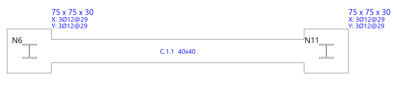
Entering tie beams and strap beams
The insertion of tie beams and centring beams is carried out with the following options in the "New" menu of the "Foundation elements" group in the "Foundation" tab: "Tie beam", "Strap beam" and "Beam with automatic balancing at the ends".
Entering tie beams
If the "Tie beam" option is selected, a pop-up window opens. In the drop-down menu at the top, the type of tie beam is selected via its "Reference".
The central display shows the dimensions and the longitudinal and transverse reinforcement associated with the selected beam type.
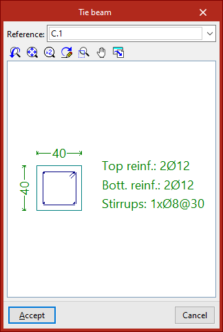
After clicking "Accept", the beam is entered in the plan by selecting the starting point and the end point of the beam with the left mouse button, using the snaps of the starts and the previously drawn elements if necessary.
Entering strap beam
If we select the "Strap beam" option, we must specify whether the beam "Balances at origin" or "Balances at end" by checking the corresponding checkboxes. At least one of the two check boxes must be activated. If you do not want to centre either end, a tie beam will be used.
Then, as in the previous case, select the type of strap beam in the "Reference" drop-down list and, after clicking "Accept", draw the beam in plan using the left mouse button.
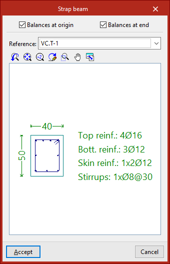
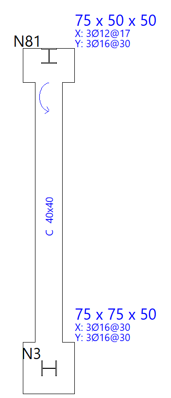
The origin and the end of a centring beam depend exclusively on the order of data entry. Once entered, we can see that circular arrows are drawn at their connection with footings or pile caps.
These arrows indicate that, at the end where they are drawn, the beam is balancing the load of the footing or pile cap in the direction of the longitudinal axis of the strap beam.
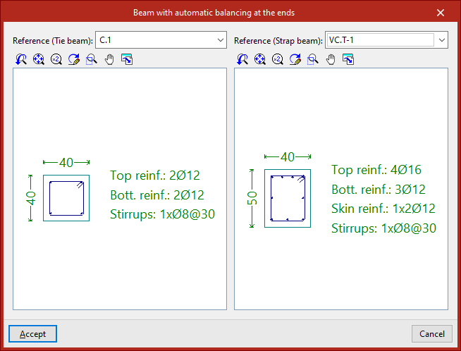
Entering beams with automatic balancing at the ends
The "Beam with automatic balancing at the ends" option allows the program to automatically identify the need for balancing loads at the ends when drawing beams in contact with corner footings or party walls.
To do this, after clicking on the option, the two possible beam types must be specified in the "Reference" drop-down menus, both in the case of a tie beam and a centring beam.
After clicking "Accept", the left button is used to enter the beam in plan in the same way as in the previous cases.
This time, the program will automatically use a tie beam if it is inserted between two centred footings, and a strap beam if one of the points of the beam is in contact with a corner or party footing, applying and displaying the centring of loads at the end where necessary.
Generating, checking and designing foundation elements
The options in the "Design" group of the "Foundation" tab automatically generate footings and beams, as well as analyse, check and/or design the foundation elements, and show or hide issues.

Generating footing and beams
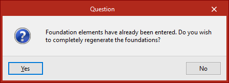
The "Generate footings and beams" option automatically creates footings and tie beams following the layout of the starting points in the floor plan.
If foundation elements have already been entered, the program then asks whether the foundation is to be completely regenerated.
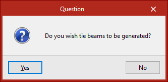
Then, in the following dialogue box, it is specified whether tie beams are to be generated.
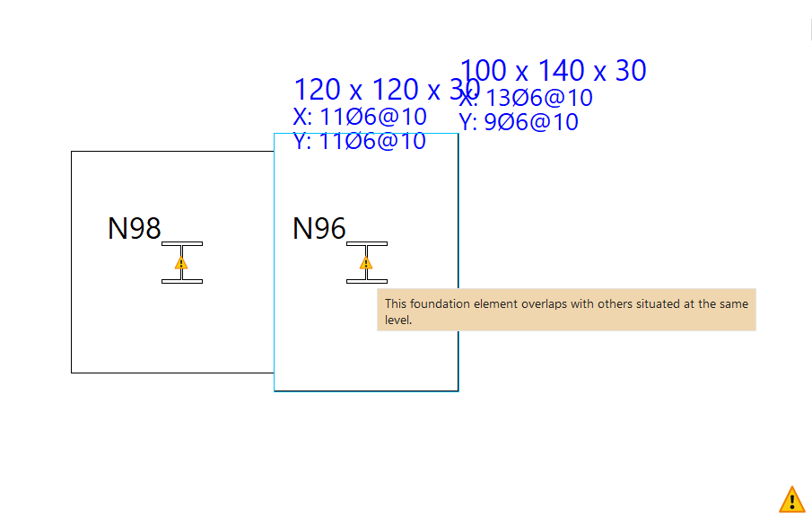
Delete overlaps
Foundation elements overlapping with others at the same elevation may be found after manually modifying their geometry or performing the joint dimensioning of the foundation.
In this case, the geometry can be modified again to avoid the situation or the "Delete overlaps" option can be used to automatically delete the overlaps.
As a result, the program will place footings common to several starts at the places where the overlaps occur.
Check
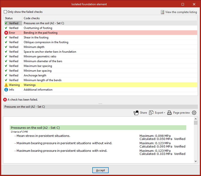
The "Check" option checks all the elements of the foundation without making any changes, both foundations, pile caps and beams.
The elements that comply with all the checks are shown in green and those that do not are shown in red.
Hovering the mouse pointer over each element displays an information box with its data.
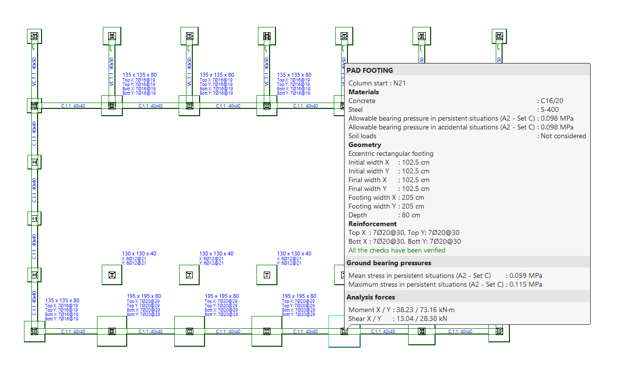
By left-clicking on each element, you can access the detailed list of checks.
By activating or deactivating the box at the top, you can indicate whether you want to "Show only the checks that are not fulfilled" or all of them.
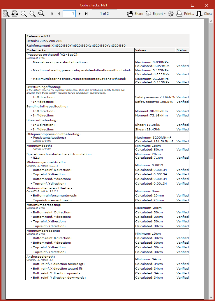
In the central part, a list is shown with the "Status" of each "Check". By clicking on each of the lines, the detailed list of each check is displayed in the lower part of the viewer.
In the upper right-hand part it is possible to "View the complete list" of each element, which can be "Shared", "Exported" in different formats or "Print".
Design
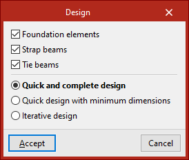
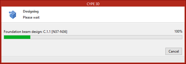
The "Design" option is used to simultaneously design the elements that make up the foundation, including both their geometry and reinforcement.
In the pop-up window that appears, the "Foundation elements", "Strap beams" and "Tie beams" boxes can be selected to define the elements to be designed.
Then, the type of design to be carried out is indicated.
- In the case of a "Quick and complete design", the design of all foundation elements is carried out in a single operation, without respecting the geometry entered by the user.
- If "Quick dimensioning with minimum dimensions" is selected, a single operation is also carried out, in this case checking the designs entered by the user and modifying them only if necessary.
- Finally, if "Iterative design" is selected, the design of all the foundation elements is carried out in three iterations, because if the stiffness of a centring beam varies, this influences the analysis of the footings to which it is linked.
After completing the design process, as with the "Check" option, hovering the mouse pointer over each element displays an information box with its data. If you click on it with the left button, you can access a detailed list of checks.
Issues
If the "Issues" option is activated, warning or error marks are displayed on the elements in which an issue has occurred.
If the mouse cursor is positioned over these marks, the error message can be displayed.