
Options in the "Geometry" tab
The upper tab "Geometry" (accessible within the lower tab "Structure") contains options for defining reference drawings and entering the geometry of nodes, bars and shells in the model, as well as various editing tools and tools for importing .dwf or .dwg files and text files. It includes the following:
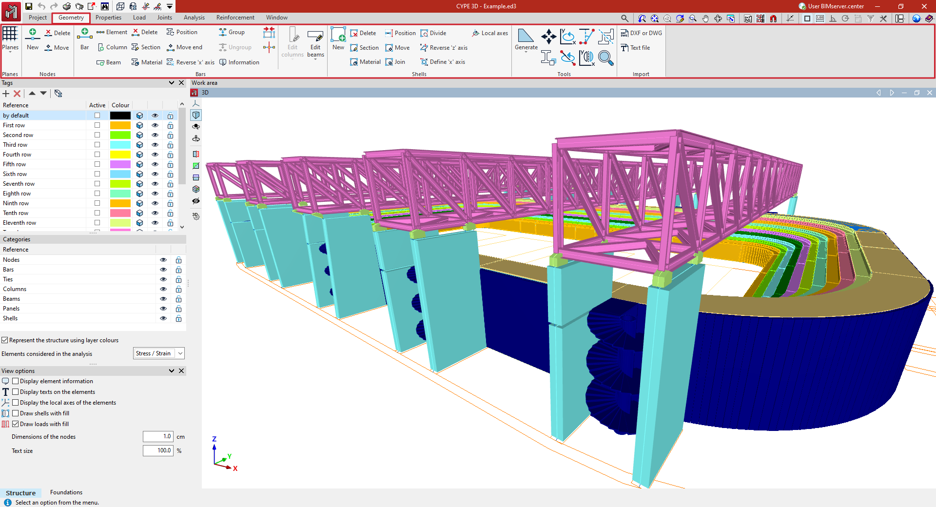
- in the "Drawings" group, the options for entering and managing grids, levels, dimensions and reference lines, which are used to support the entry of structural elements;
- in the "Nodes" group, the options for entering structural nodes;
- in the "Bars" group, the options for entering the geometry of the bars, parts, columns and beams of the structure, as well as those that allow the editing of their section and material, their layout and grouping;
- in the "Shells" group, the options for entering and editing the geometry of the sheets of the structure, their section and material;
- in the "Tools" group, the options that allow the automatic generation of the structure geometry, as well as the tools for editing it;
- and in the "Import" group, the options that allow the import of the structure geometry from the information contained in .dxf or .dwg files or in text files.
Entering nodes
Nodes are inserted using the tools available in the "Nodes" group of the top toolbar, within the "Geometry" tab (in the "Structure" tab).

New
The "New" option is used to insert a new node into the structure. Nodes can be inserted in several ways:
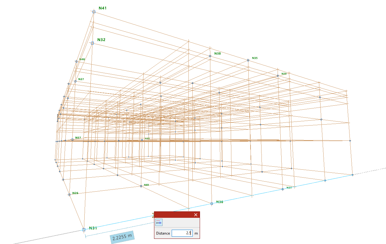
Inserting nodes on reference lines or bars
After selecting the "New" option, left-click on the desired position on a reference line or bar in the work area.
| Note: |
|---|
| To activate the visibility of reference lines, use the "References" option from the "Drawings" menu, within the "Geometry" tab. Users can rely on "Template object snaps" and "Object Snap" to enter the node. The "Allows for dimensions to be defined upon entering each element" option can also be useful for entering the "Distance" between the node and the specified reference point. These options are located in the toolbar at the top right. |
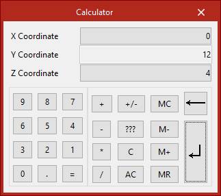
Numerical or coordinate input of nodes
Nodes can also be inserted by typing in their coordinates directly.
To do this, after selecting the option, press the numeric keypad on your computer. A "Calculator" will appear on the screen to enter the X, Y, and Z coordinate data.
| Note: |
|---|
| To enter the knot by coordinates, the "Enter by coordinates" option on the toolbar at the top right can be used. |
Entering nodes directly
If the window corresponds to a 2D view, users can left-click anywhere on the drawing to enter the node.
Delete
The "Delete" option is used to delete a node or a set of nodes. To do this, select each node to be deleted individually or draw a selection box around them using the left mouse button. Then, click the right mouse button.
| Note: |
|---|
| When deleting nodes, the bars that reach those nodes are also automatically deleted. |
Move
The "Move" option is used to move a node to a new position. After selecting the option, click on the node with the left mouse button and then on its new position. This action will also modify the geometry of the bars that reach that node.
If you do not wish to perform the operation, it can be cancelled by clicking the right mouse button.
Entering bars
Bars are entered using the tools available in the "Bars" group of the top toolbar, within the "Geometry" tab (in the "Structure" tab).

Bar
The "Bar" option is used to insert a new bar into the structure.
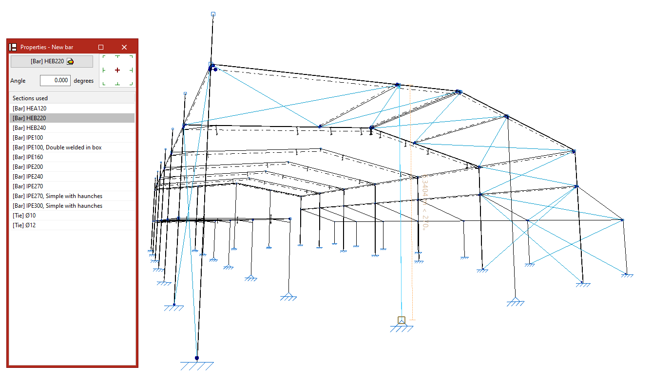
Defining the properties of the bar
In the "Properties - New bar" panel that appears, the main button is used to "Describe" the section.
Users can modify the "Angle" and, on the right, the layout with respect to the input line.
The table below shows the "Sections used" previously in the job. They can all be selected directly.
Entering a bar into the work area
Each bar is defined by its start and end nodes, so to enter it, two points must be selected with the left button in the "Work area".
These can be nodes previously entered using the options in the "Nodes" group or points in space yet to be determined.
| Note: |
|---|
| Users are provided with various aids for entering these points in the work area In the "Drawing" menu, users can select the “References” option and activate the "Show grid" and "Reference lines" options. To activate the snaps of other elements already inserted in the model, the "Object Snap" option is used. Users can also click on the "Allows for dimensions to be defined upon entering each element" option to write the value of the "Length" of the bar when entering it. On the other hand, the "Orthogonality" and "Polar tracking" options force the direction of the bar at the moment of insertion. If desired, users can also use "Coordinate entry", and if a template has been entered in the program, the "Template object snaps" are used. These options are available in the top right toolbar. |
Inserting consecutive bars
After entering a bar, further bars can be entered by left-clicking on other points. To finish entering bars, click the right mouse button.
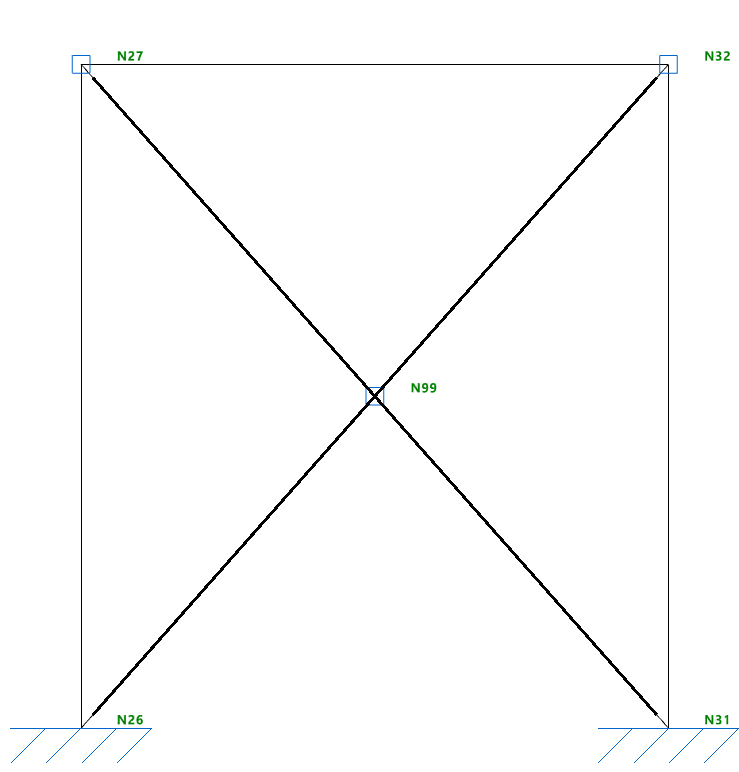
Generating nodes at crossbar cut-off points
When entering two cross bars, you can keep the "Generate nodes at intersection points" option activated in the "Bars" group so that the program automatically generates a node defined as an inner link at the point of contact of the bars.
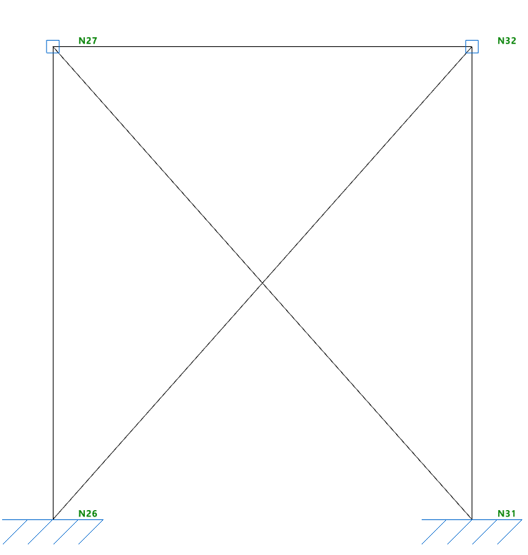
If kept deactivated, the bars will be unlinked in the model and a node will not be generated at the intersection point.
Delete
The "Delete" option is used to delete a bar.
To do this, make an individual selection by left-clicking on each bar or draw a selection window. When drawing from left to right, this window selects the bars that are completely contained within it. When drawing from right to left, the bars that are completely or partially contained within it are selected. The selection of a bar can be carried out by left-clicking with the mouse while holding down the "Shift" key.
By pressing the right button, the program will delete the bars.
| Note: |
|---|
| The nodes formed at the ends of the deleted bar will remain in the model. |
Move end
The "Move end" option is used to change the position of one of the end nodes of a bar. To do this, select the node by left-clicking on it and then click on its new position.