
Options in the "Geometry" tab
The upper tab "Geometry" (accessible within the lower tab "Structure") contains options for defining reference drawings and entering the geometry of nodes, bars and shells in the model, as well as various editing tools and tools for importing .dwf or .dwg files and text files. It includes the following:
- in the "Drawings" group, the options for entering and managing grids, levels, dimensions and reference lines, which are used to support the entry of structural elements;
- in the "Nodes" group, the options for entering structural nodes;
- in the "Bars" group, the options for entering the geometry of the bars, parts, columns and beams of the structure, as well as those that allow the editing of their section and material, their layout and grouping;
- in the "Shells" group, the options for entering and editing the geometry of the sheets of the structure, their section and material;
- in the "Tools" group, the options that allow the automatic generation of the structure geometry, as well as the tools for editing it;
- and in the "Import" group, the options that allow the import of the structure geometry from the information contained in .dxf or .dwg files or in text files.
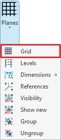
Entering and editing grids
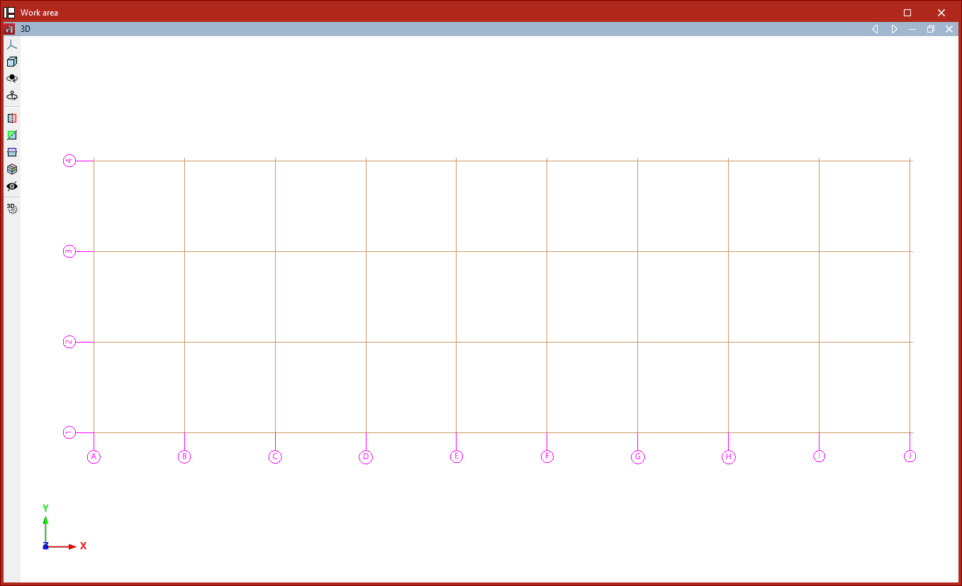
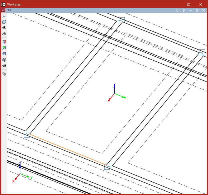
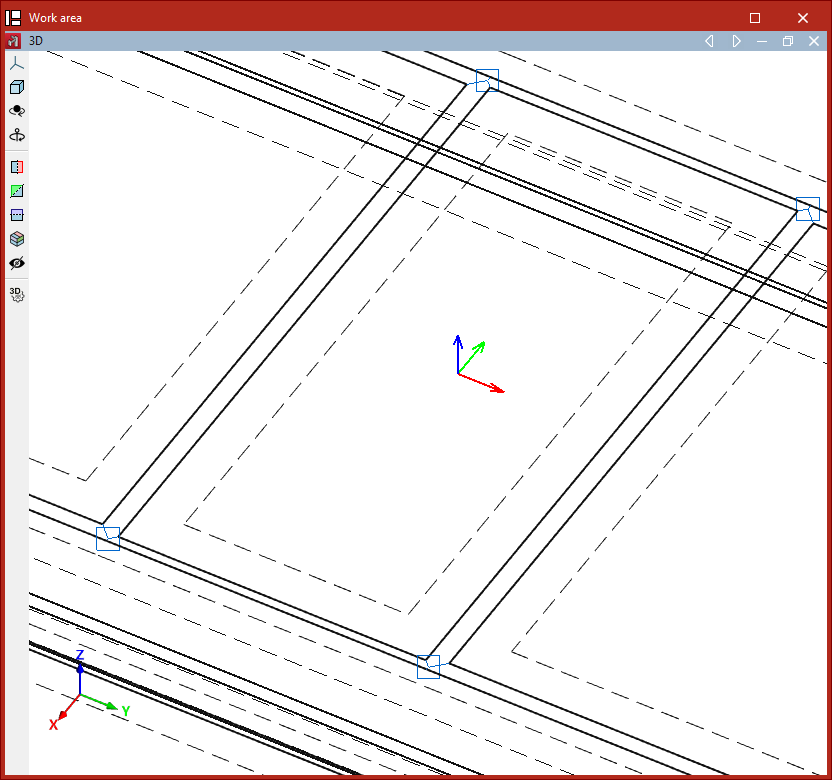
A grid can be added to the model using the "Grid" tool, available in the "Planes" menu within the group of the same name on the top toolbar, under the "Geometry" tab (on the "Structure" subtab):

Grids
A grid is a framework made up of lines parallel to the global X and Y axes. These lines divide the model spatially into elevations, which serve as a reference for entering structural elements and for defining elevation views.
After clicking on the "Grid" option, a window opens where the lines that make up the grid can be defined manually or generated automatically.
Entering gridlines manually
In the "Lines in X direction" and "Lines in Y direction" tables, you can manually "Add", "Copy", and "Delete" gridlines.
By clicking "Add", you can enter the data for a "New line", specifying its "Coordinate" relative to the origin, a "Label" to identify the line, and the "Label position" at either the "Origin" or the "End" of the line.
This process can be repeated to define the remaining gridlines.
The program also provides an option to "Adjust the elements of the model by changing the position of the gridlines". This means that if you modify the coordinates of the gridlines in this panel, any structural elements associated with those lines will automatically update their position.
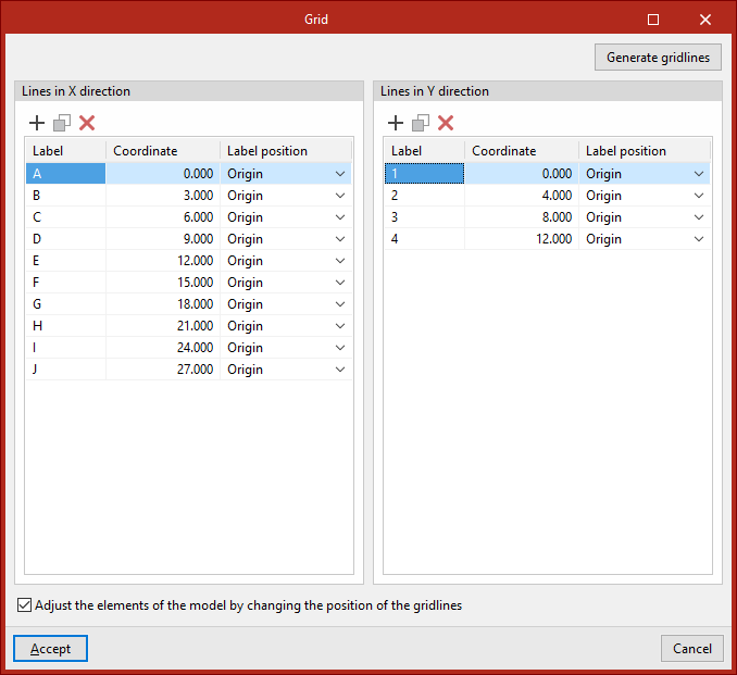
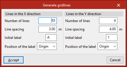
Generating gridlines
Gridlines can also be generated automatically. To do this, click the "Generate gridlines" button.
In this case, for both the "Lines in X direction" and the "Lines in Y direction", you define the "Number of lines", the "Line spacing", the "Initial label", and the "Position of the label".
Then, click "Accept". The program will delete any previously defined gridlines, if they exist, and insert the new ones into the tables.
You are free to modify the data of the generated gridlines.
Finally, in the "Grid" window, click "Accept" to return to the main interface.
| Note: |
|---|
| To check the visibility of the grid and its associated reference lines, open the "Planes" menu and click on the "References" option. Then tick the boxes "Show grid" and "Reference lines", while leaving "Only those with a node" unticked. |
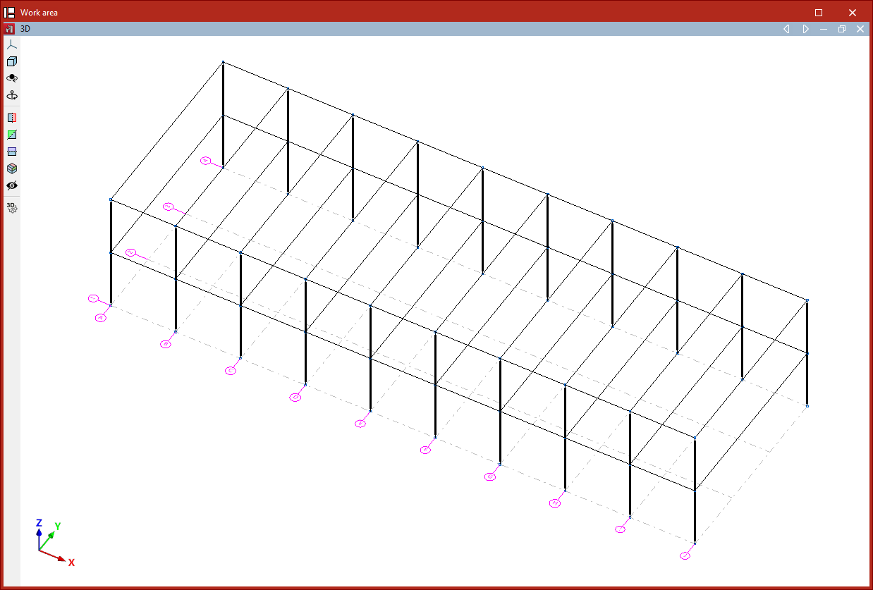
From this point on, nodes, bars, and other structural elements can be entered along the reference lines generated by the grid. Elements contained within the planes defined by the gridlines will be associated with them.
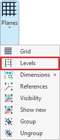
Entering levels
Levels are defined in the model using the "Levels" tool, available in the "Plans" menu of the group with the same name in the top toolbar, within the "Geometry" tab (under the "Structure" tab).
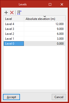
Levels
Levels are horizontal planes parallel to the global XY plane, located at a specific elevation, and serve as a base for inserting structural elements and defining level-based views. Dividing a structure into levels is characteristic of building models.
After clicking on the "Levels" option, a window opens where levels can be defined manually or generated automatically.
Manually inserting levels
The tools at the top of the levels list allow you to "Add" and "Delete" levels manually. To "Add" a level, click on the first option. Then, enter the "Reference" and the "Absolute level" relative to the global coordinate origin, which can be either positive or negative.
When more levels are added, the program automatically sorts them in the table by elevation.
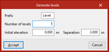
Generating levels
Levels can also be "Generated" automatically using the button on the right side of the top toolbar in the levels list.
To do this, enter a "Prefix" for the level references, the "Number of levels" to generate, the "Initial level" from which they are generated, and the "Spacing" between each level.
After clicking "Accept", the program will delete any previously defined levels and replace them with the automatically generated ones.
| Note: |
|---|
| The "Reference" or "Absolute level" of an automatically generated level can be edited directly by clicking on the corresponding cells in the levels list. |
To finish, click "Accept".
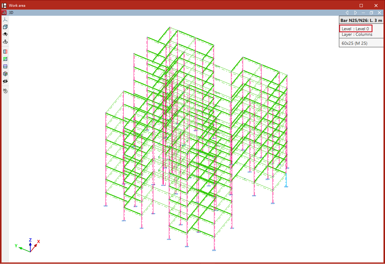
Assigning elements to levels
The program assigns model elements to the different levels automatically—both existing elements and those inserted from this point onwards.
To check the level of a shell, open the "Geometry" tab and select the "Information" option from the "Shell" group. Then, hover the pointer over the elements.
If an element is located at a level's elevation, it is assigned to that level. Elements positioned between two levels (such as columns) are assigned to the lower level.
Selecting levels in columns
Defining levels is useful in models that include "Column" and "Beam" type elements.
When inserting columns, at least two levels must be defined in advance. To select them, open the "Geometry" tab and select "Column" within the "Bar" group. Then, in the "Levels" section of the pop-up window, choose the "Final level" and the "Initial level" of the column from the dropdown menus. Additionally, specify the section of the column for each interval defined between levels.
On the other hand, defining levels is not required to insert beams, but doing so can make the task easier.
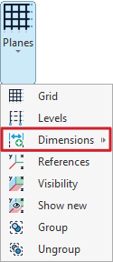
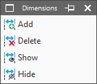
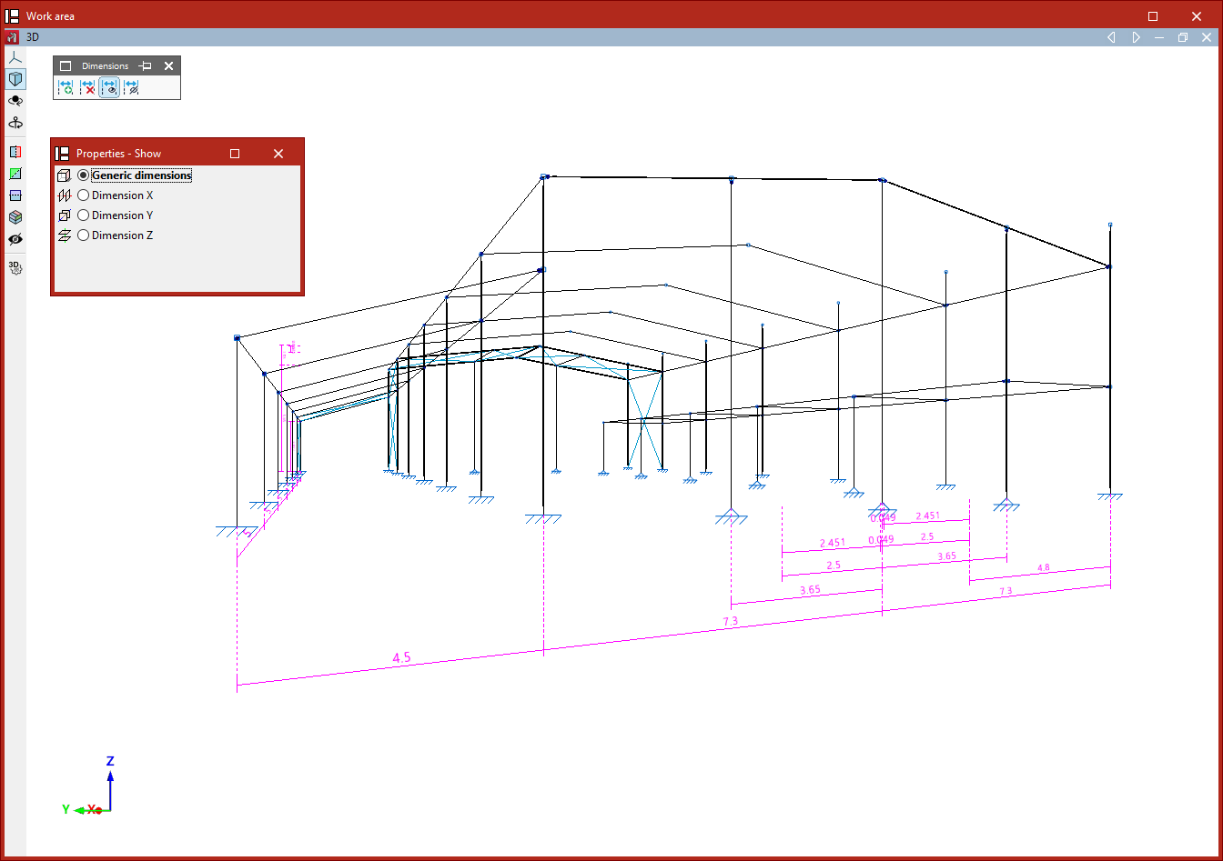
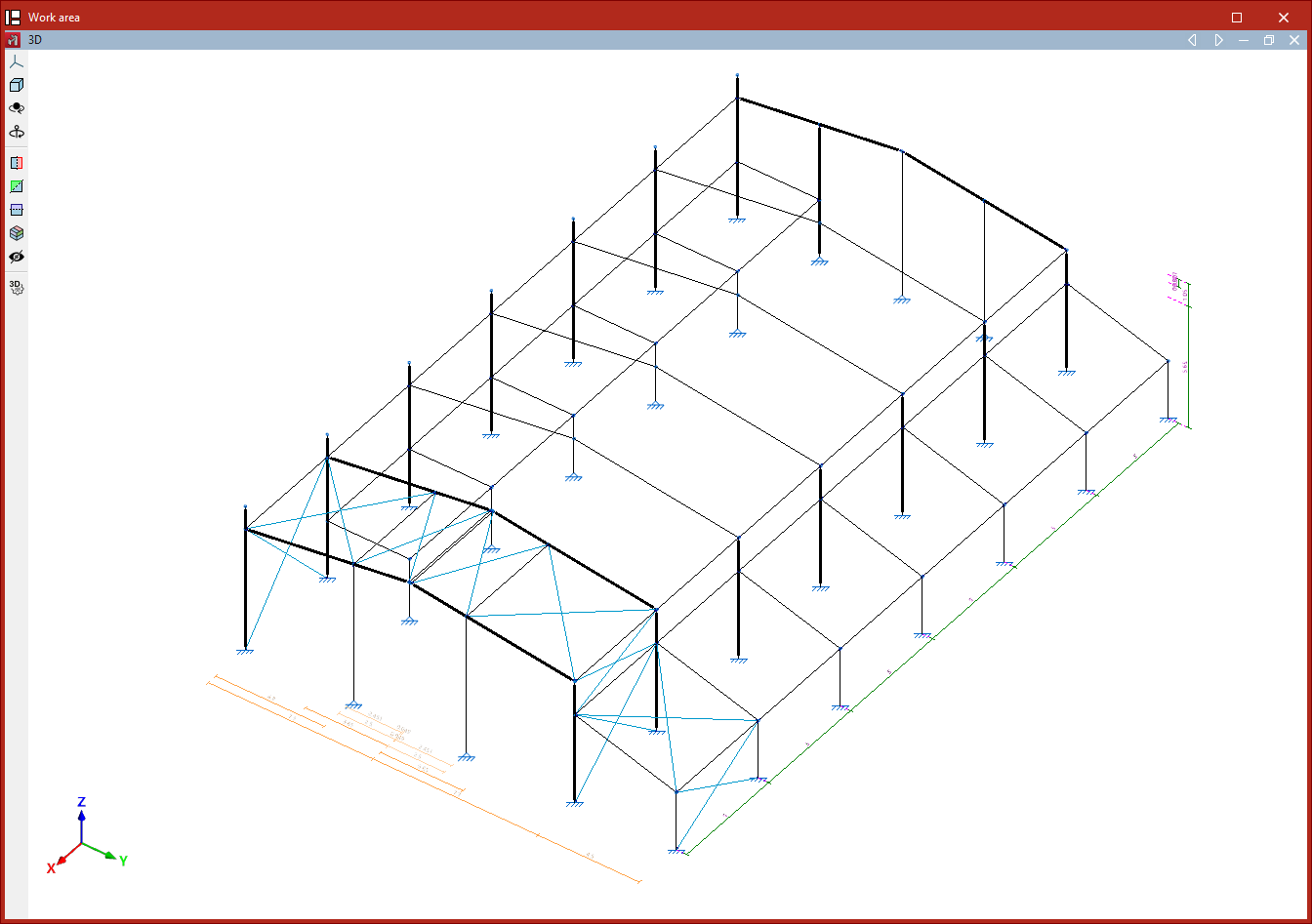
Inserting dimensions
Dimensions are inserted and managed using the tools under the "Dimensions" option, available in the "Planes" menu of the group with the same name in the top toolbar, within the "Geometry" tab (under the "Structure" section).
Clicking on the "Dimensions" option opens a window with the following functions:
- Add
- Delete
- Show
- Hide
Each of these functions is explained below:
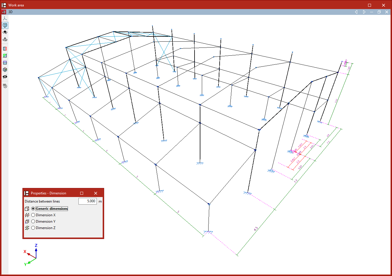
Adding dimensions
The first option, "Add", allows you to modify the model’s dimensions by inserting dimensions between geometric elements.
You must enter the "Distance between lines" that will apply when the dimension is inserted, and specify whether a "Generic dimension" will be used in any direction in space, or if you wish to "Dimension X", "Dimension Y", or "Dimension Z".
After selecting the desired option, use the left mouse button to select two reference lines, two bars, or two nodes between which the dimension will be inserted.Alternatively, you can left-click on an existing dimension displayed in the model to assign it a new value.
In any case, the model geometry will adjust after the dimension is inserted.
| Note: |
|---|
| The program automatically generates dimensions when elements such as bars or shells are inserted into the model. |
Deleting dimensions
The next option allows you to "Delete" dimensions.
Again, choose the type of dimension to be deleted. If "Generic dimension" is selected, any type of dimension can be removed. The other options—"Dimension X", "Dimension Y", and "Dimension Z"—allow dimensions in the corresponding directions to be deleted.
Then, using the left mouse button, select dimensions one by one or mark a capture area. Right-click to delete the selected dimensions.
This operation does not modify the model geometry.
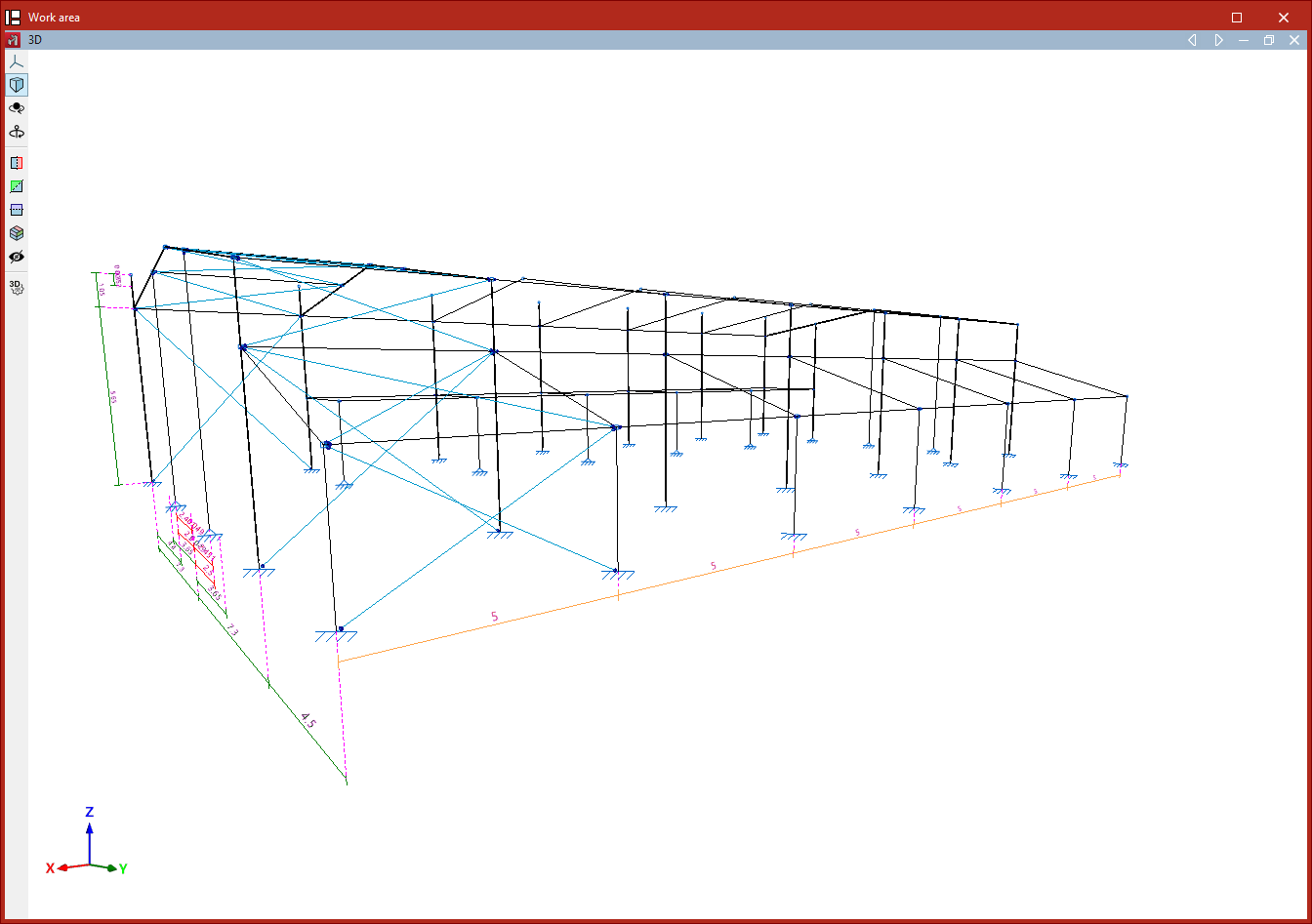
Dimension deletion process
Showing dimensions
The "Show" option allows you to insert additional dimensions to improve clarity in drawings or on screen.
Dimensions inserted using this option do not affect the model’s dimensions; they are for information display only.
Again, choose whether to perform a "Generic dimension" or to "Dimension X", "Dimension Y", or "Dimension Z".
Then select two reference lines or two nodes using the left mouse button. The program will insert the dimension, displaying the measured distance between them.
Hiding dimensions
The "Hide" option allows you to select dimensions in the workspace to hide them from drawings only.
After clicking the option and selecting the type of dimension to be hidden, use the left mouse button to select dimensions one by one or mark a capture area, and then right-click to complete the process.
In this case, the dimension is not removed from the model.
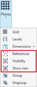
Visibility of planes and reference lines
The display of planes and reference lines is managed using the tools available in the "Planes" menu of the group with the same name in the top toolbar, within the "Geometry" tab (under the "Structure" section).
Reference lines are graphical supporting elements perpendicular to the global axes, which make the insertion of new structural elements easier by enabling snapping.
The options related to the visibility of reference lines are:
- References
- Visibility
- Show new
Each of these tools is explained below:
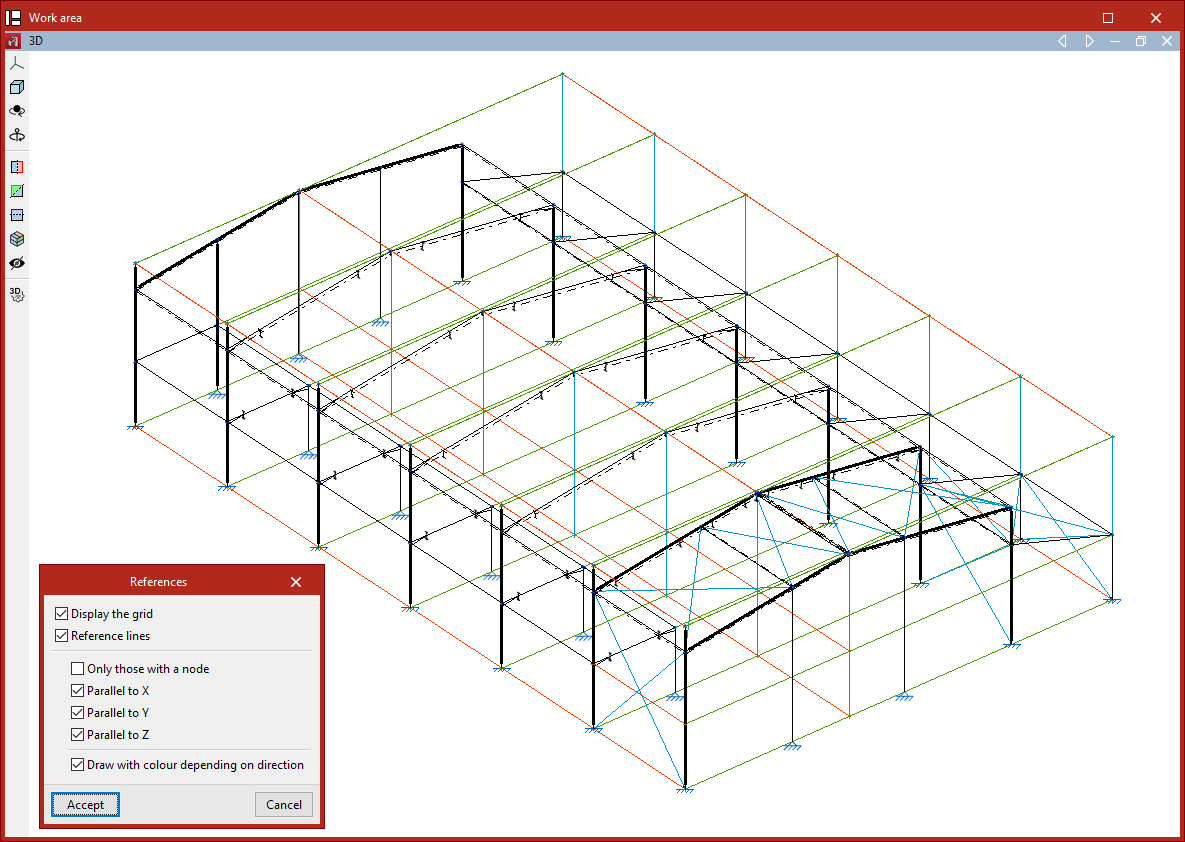
References
The "References" option opens a dialogue box where you can tell the program whether to "Display the grid" (inserted using the "Grid" option in the same menu) and manage the visibility of "Reference lines" by checking or unchecking the corresponding boxes.
Within the reference lines section, you can choose to display "Only those with a node", or only lines that are "Parallel to X", "Parallel to Y", or "Parallel to Z".
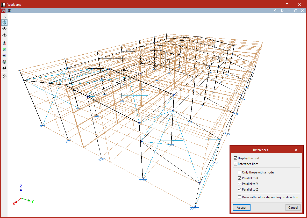
If the "Draw with colour depending on direction" checkbox is enabled, the program will display the reference lines using a different colour for each of the three spatial directions.
Click "Accept" to apply the changes to the model.
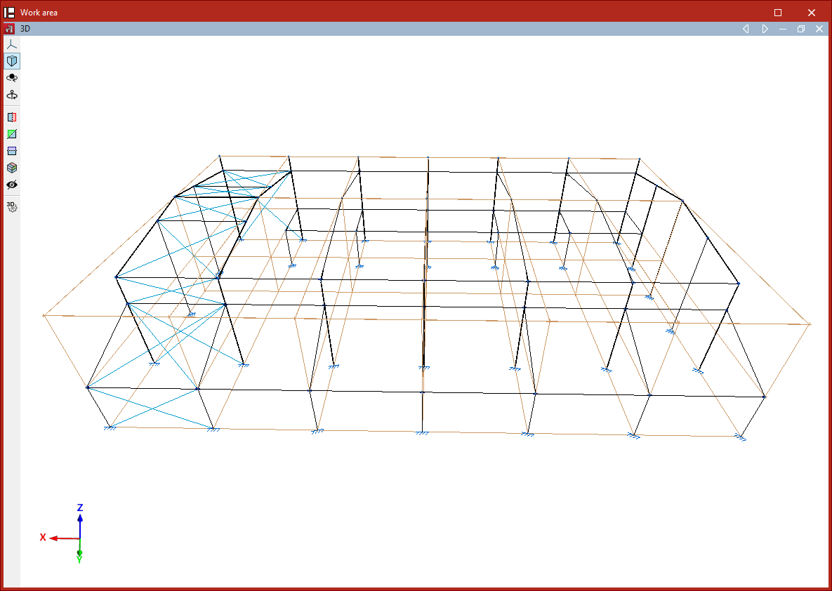
Visibility
The "Visibility" option allows you to select a group of nodes and either show or hide the reference lines of the planes that contain them.
To do this, in the "Show/Hide planes" dialogue box that appears after clicking the option, first choose whether to "Show" or "Hide" the lines by selecting the corresponding option, then click "Accept".
Next, select the group of nodes where the setting should be applied by left-clicking on them one by one, or by marking a selection area.
Finally, confirm the operation by right-clicking.
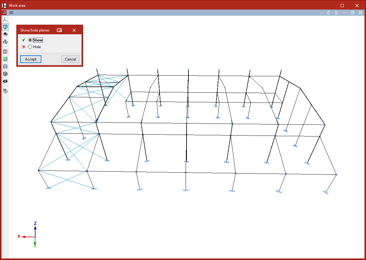
Process to hide or show reference lines in planes
Show new
The "Show new" option manages the visibility of reference lines in planes generated when new nodes are inserted into the structure.
If this option is active (it will appear highlighted in the "Planes" menu), then when nodes are inserted—whether by using the dedicated insert nodes option or by inserting the ends or vertices of bars or shells—the reference lines associated with them will be visible.
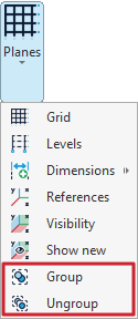
Grouping and ungrouping planes
The tools for grouping and ungrouping planes can be found in the "Planes" menu within the group of the same name on the top toolbar, under the "Geometry" tab (in the "Structure" tab).
Group
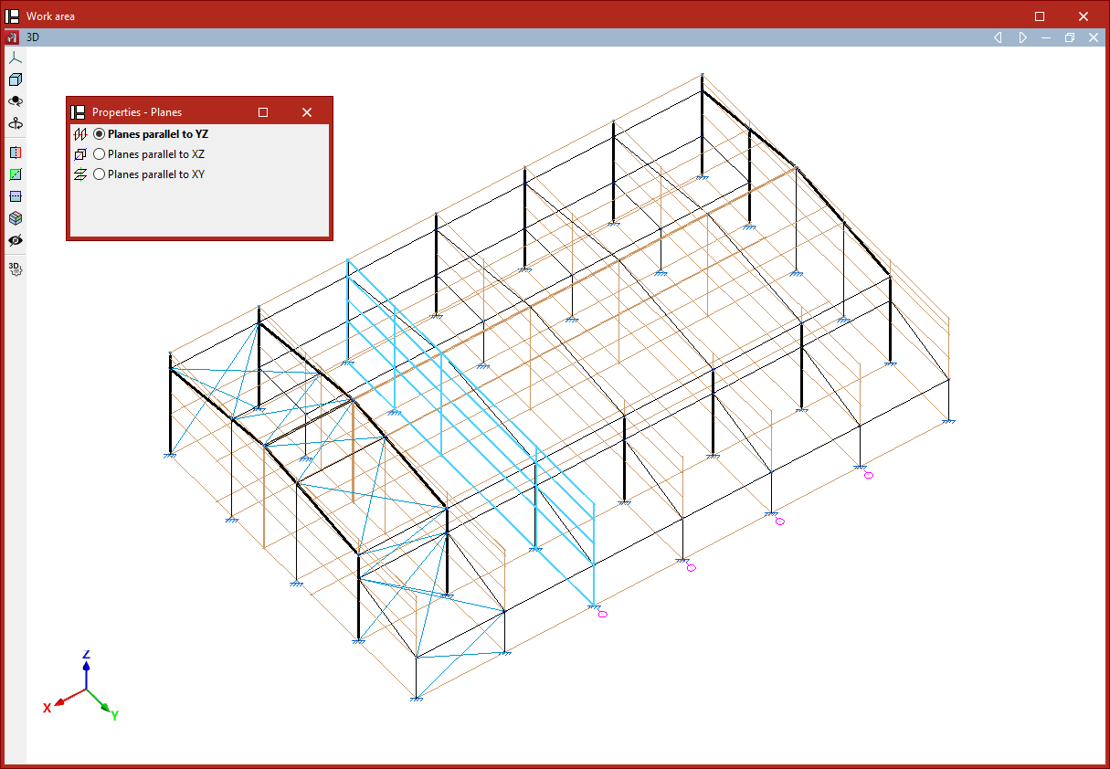
The "Group" option is used to group parallel planes, ensuring that the elements they contain, as well as their positions, remain exactly the same across all planes in the group.
After selecting the option, you choose whether to group "Planes parallel to YZ", "Planes parallel to XZ" or "Planes parallel to XY".
The program allows you to select the planes one by one using the left mouse button. After selecting them, right-click and respond to the prompt in the dialogue box that appears to complete the operation.
A reference number will now be visible next to each plane in the model. This number is common to each group of planes and is used to identify them.
Any changes made to a plane within a group, such as inserting a node or a bar contained within it, will be reflected in the other grouped planes.
Ungroup
You can "Ungroup" planes using the following menu option.
Similarly, choose whether to ungroup "Planes parallel to YZ", "Planes parallel to XZ" or "Planes parallel to XY", then click "OK".
Now, select the planes you want to remove from the group using the left mouse button. Finally, right-click and respond to the prompt in the dialogue box to complete the operation.
Entering nodes
Nodes are inserted using the tools available in the "Nodes" group of the top toolbar, within the "Geometry" tab (in the "Structure" tab).

New
The "New" option is used to insert a new node into the structure. Nodes can be inserted in several ways:
Inserting nodes on reference lines or bars
After selecting the "New" option, left-click on the desired position on a reference line or bar in the work area.
| Note: |
|---|
| To activate the visibility of reference lines, use the "References" option from the "Drawings" menu, within the "Geometry" tab. Users can rely on "Template object snaps" and "Object Snap" to enter the node. The "Allows for dimensions to be defined upon entering each element" option can also be useful for entering the "Distance" between the node and the specified reference point. These options are located in the toolbar at the top right. |
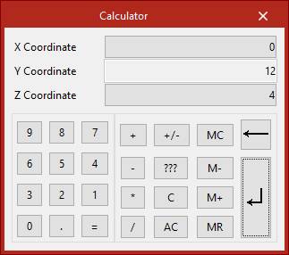
Numerical or coordinate input of nodes
Nodes can also be inserted by typing in their coordinates directly.
To do this, after selecting the option, press the numeric keypad on your computer. A "Calculator" will appear on the screen to enter the X, Y, and Z coordinate data.
| Note: |
|---|
| To enter the knot by coordinates, the "Enter by coordinates" option on the toolbar at the top right can be used. |
Entering nodes directly
If the window corresponds to a 2D view, users can left-click anywhere on the drawing to enter the node.
Delete
The "Delete" option is used to delete a node or a set of nodes. To do this, select each node to be deleted individually or draw a selection box around them using the left mouse button. Then, click the right mouse button.
| Note: |
|---|
| When deleting nodes, the bars that reach those nodes are also automatically deleted. |
Move
The "Move" option is used to move a node to a new position. After selecting the option, click on the node with the left mouse button and then on its new position. This action will also modify the geometry of the bars that reach that node.
If you do not wish to perform the operation, it can be cancelled by clicking the right mouse button.
Entering bars
Bars are entered using the tools available in the "Bars" group of the top toolbar, within the "Geometry" tab (in the "Structure" tab).

Bar
The "Bar" option is used to insert a new bar into the structure.
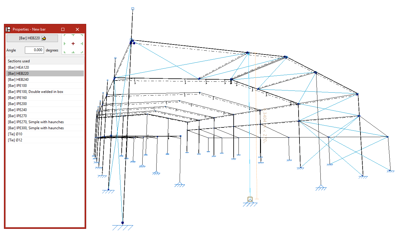
Defining the properties of the bar
In the "Properties - New bar" panel that appears, the main button is used to "Describe" the section.
Users can modify the "Angle" and, on the right, the layout with respect to the input line.
The table below shows the "Sections used" previously in the job. They can all be selected directly.
Entering a bar into the work area
Each bar is defined by its start and end nodes, so to enter it, two points must be selected with the left button in the "Work area".
These can be nodes previously entered using the options in the "Nodes" group or points in space yet to be determined.
| Note: |
|---|
| Users are provided with various aids for entering these points in the work area In the "Drawing" menu, users can select the “References” option and activate the "Show grid" and "Reference lines" options. To activate the snaps of other elements already inserted in the model, the "Object Snap" option is used. Users can also click on the "Allows for dimensions to be defined upon entering each element" option to write the value of the "Length" of the bar when entering it. On the other hand, the "Orthogonality" and "Polar tracking" options force the direction of the bar at the moment of insertion. If desired, users can also use "Coordinate entry", and if a template has been entered in the program, the "Template object snaps" are used. These options are available in the top right toolbar. |
Inserting consecutive bars
After entering a bar, further bars can be entered by left-clicking on other points. To finish entering bars, click the right mouse button.
Generating nodes at crossbar cut-off points
When entering two cross bars, you can keep the "Generate nodes at intersection points" option activated in the "Bars" group so that the program automatically generates a node defined as an inner link at the point of contact of the bars.
If kept deactivated, the bars will be unlinked in the model and a node will not be generated at the intersection point.
Delete
The "Delete" option is used to delete a bar.
To do this, make an individual selection by left-clicking on each bar or draw a selection window. When drawing from left to right, this window selects the bars that are completely contained within it. When drawing from right to left, the bars that are completely or partially contained within it are selected. The selection of a bar can be carried out by left-clicking with the mouse while holding down the "Shift" key.
By pressing the right button, the program will delete the bars.
| Note: |
|---|
| The nodes formed at the ends of the deleted bar will remain in the model. |
Move end
The "Move end" option is used to change the position of one of the end nodes of a bar. To do this, select the node by left-clicking on it and then click on its new position.
Creating elements
Elements are created using the following tool, available in the "Bars" group on the top toolbar, within the "Geometry" tab (in the "Structure" tab).

Creating elements is a necessary operation for certain processes, such as generating connections with columns or continuous beams, or identifying braced panels with intermediate nodes.
Creating elements
The "Element" option allows a group of aligned bars between two selected nodes to be defined as a single continuous element.
After clicking on the option, the initial node of the first bar and the final node of the last bar forming the element are selected using the left mouse button.
The program displays a dialog box to confirm the operation. After clicking "Yes", an element is created between the selected nodes.
Bars forming a single element are drawn with a thick line in the model to differentiate them from independent bars.
If you wish to divide an element, the "Element" option is used again, but this time the two consecutive nodes of one of the bars forming it are selected.
The program will undo the element, returning to independent bars. These will be displayed with a thin line.
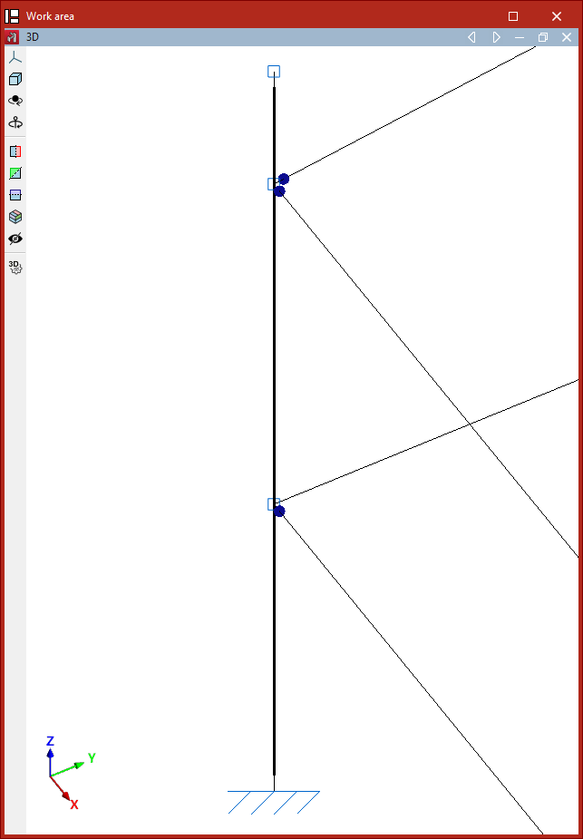
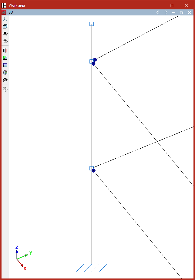
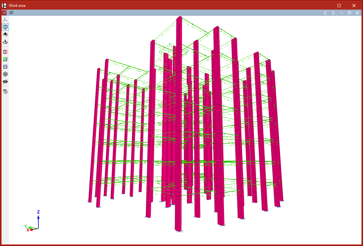
Entering columns
Columns are entered using the "Column" option, available in the "Bars" group on the top toolbar, within the "Geometry" tab (in the "Structure" tab).

To proceed, at least two levels must have been previously defined in the project. Levels can be viewed, created, or deleted from the "Drawings" menu at the top of the interface, also in the "Geometry" tab, by selecting the "Levels" option.
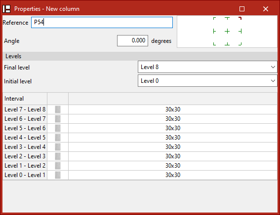
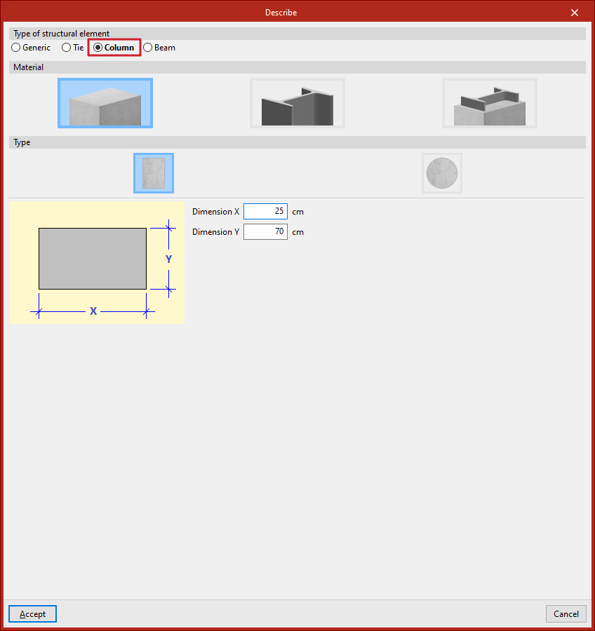
Defining column properties
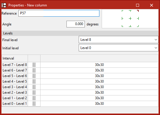
The "Column" option allows you to enter a new column. When this option is selected, a pop-up window ("Properties – New column") appears, where its characteristics are defined.
Here, the "Reference" of the column and its "Rotation angle" are entered. In the diagram on the right, the positioning of the section relative to the insertion line can be adjusted by clicking the centre, edge, or corner markers.
Next, under the "Levels" section, select the "Top level" and "Bottom level" of the column from the dropdown menus.
In the lower table, the section of the column is specified for each of the "Intervals" defined between levels.
To do this, click the cells in the right-hand column. A window will open where the "Type of section" can be modified. By holding down the Ctrl key, you can select multiple intervals at once by clicking on them one by one. If you press the Shift key, you can select a range of intervals by clicking the final and initial interval. This way, the same section can be applied to all selected intervals.
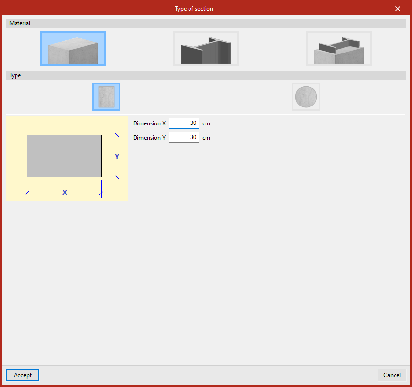
Defining the column section type
Under the "Material" section, choose whether the column is "Reinforced concrete", "Steel", or "Composite section".
Reinforced concrete columns
For "Reinforced concrete" columns, the next step is to specify the "Type".
Rectangular concrete columns
If the column is "Rectangular", enter its "X dimension" and "Y dimension", following the directions of the local coordinate axes of the element.
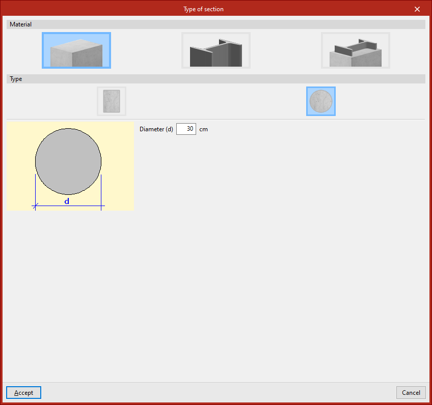
Circular concrete columns
If the column is "Circular", its "Diameter" is defined.
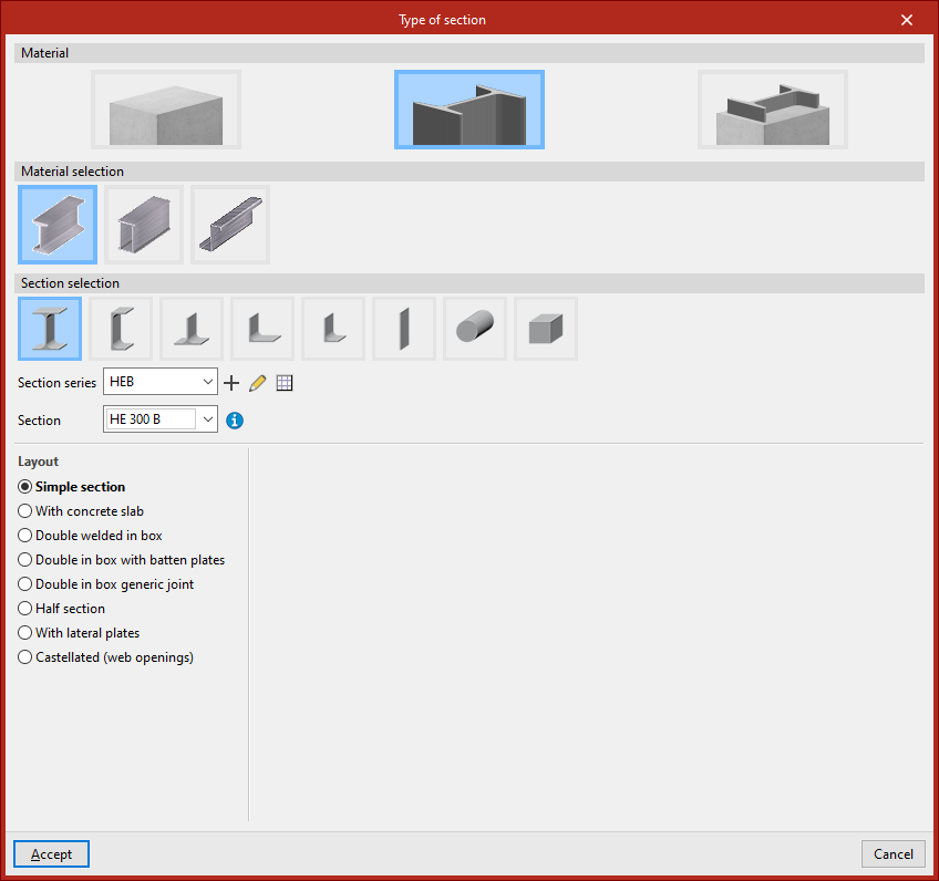
Steel columns
For "Steel" columns, you must perform both the "Material selection" and the "Section series" from the options available in the program. These are very similar to those used when inserting generic rolled or cold-formed steel bars.
Composite section columns
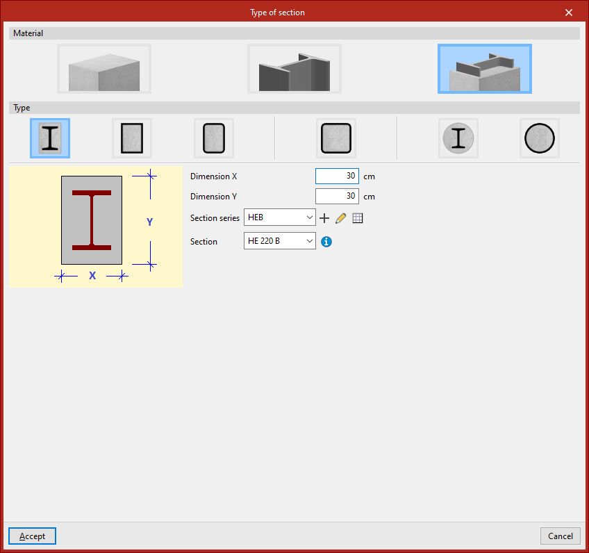
For "Composite section" columns, first select the "Type".
Concrete columns with embedded sections
For a "Rectangular column with encased section", enter the total section’s "Dimension X" and "Dimension Y", then define the "Section series" and select the "Section" of the embedded element.
Similarly, for a "Circular column with encased section", specify the "Diameter", and again select the appropriate "Section series" and "Section", as in the previous case.
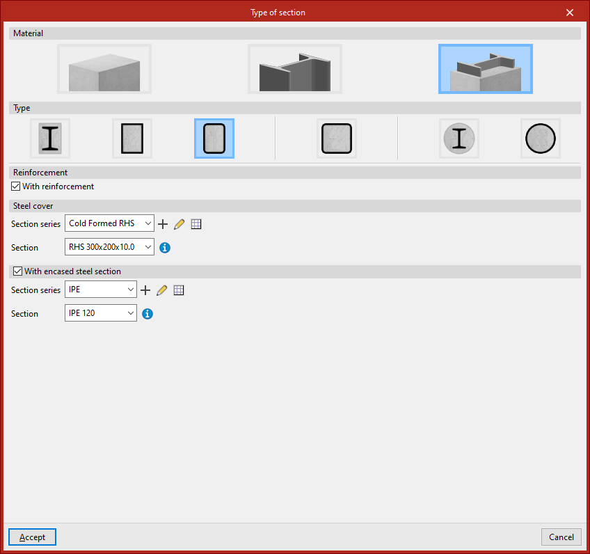
Concrete-filled steel box and tube sections
A "Rolled steel plate rectangular box section, filled with concrete" can also be inserted.
In this case, under the "Reinforcement" section, tick the "With reinforcement" box if the column includes reinforcement. Then, under "Steel cover", define the "Section series" and select the "Section" that forms the outer tube or box.
You can also tick the "With encased steel section" box. Again, indicate the "Section series" and select the "Section" of the element embedded in the concrete.
Other available options include entering a "Rectangular hollow section", "Square hollow section", or "Cold-formed circular hollow section, filled with concrete", all of which are used similarly. Once the section type has been defined, click "Accept". Then, repeat the process for the remaining intervals.
Inserting the column in the model
Finally, select a point with the left mouse button to place the column in the model.
The program will position the column vertically at the selected point, adjusting the height of the elements so they reach the specified levels.
An element is created between each pair of levels along the height of the column.
Inserting columns via the "Bar" option
You can also insert a column using the "Bar" option from the "Bars" group. Then, click the central edit button and, under the "Type of structural element" section, select "Column".
In this case, after clicking "Accept", when inserting the points that define the start and end nodes in the model, ensure that the geometry of the element is completely vertical.
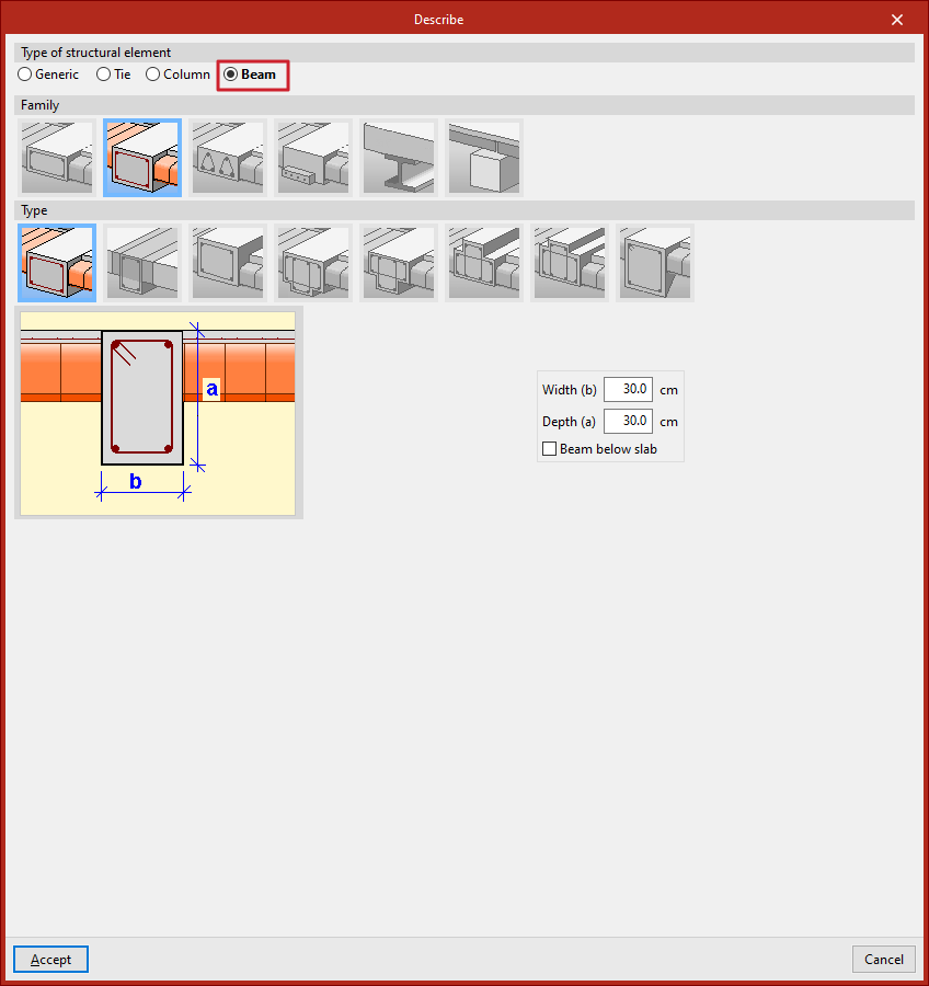
Entering beams
Beams are inserted using the "Beam" option, available in the "Bars" group of the top toolbar, under the "Geometry" tab (in the "Structure" tab).

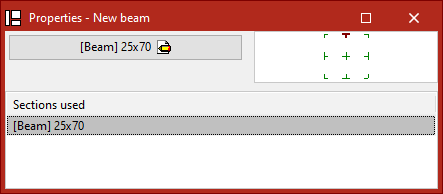
Defining the properties of the beam
In the window that appears when clicking on the "Properties – New beam" option, the diagram on the right allows adjustment of the section position relative to the input line by clicking on the centre, edge, or corner markers.
If beams have already been inserted in the model, the program allows selecting one of the "Sections used" from the table at the bottom.
If this is the first beam being inserted, or if a new section is to be "Described", click the central button.
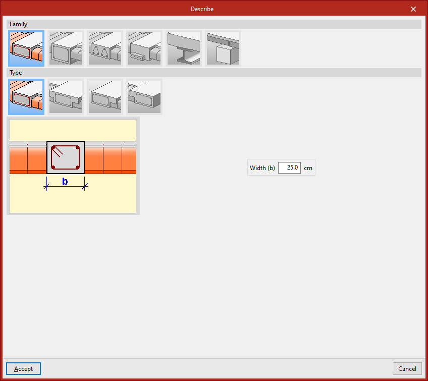
In the pop-up window, the program allows you to specify the "Family" and "Type" of beam to be inserted, along with its dimensions and characteristics.
The available beam families are described below.
Flat beams
"Flat beams" are those with the same depth as the slab. The available types of flat beams include:
- Flat rectangular beam
- Flat 'T' beam
- Flat beam with right flange
- Flat beam with left flange
Flat beams will automatically adopt the depth of the panel in which they are located. Therefore, the program only requires the definition of their "Width (b)". If the beam is located between two panels of different depths, it will take the greater of the two. If positioned between two panels at different levels, the beam depth will increase to cover the height difference.
Dropped beams
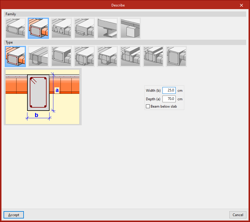
"Dropped beams" have a depth different from the slab. Available types of dropped beams include the following:
- Dropped rectangular beam
You must specify the "Width (b)" and "Depth (a)". If the "Beam below slab" checkbox is ticked, the top face of the beam aligns with the bottom face of the slab. If left unticked, it aligns with the top face of the slab.
- Dropped rectangular beam with collaborating head
In this case, you must also specify the lengths of the "Left flange (i)" and "Right flange (d)" of the concrete section that works together with the beam.
- Inverted rectangular beam
This type aligns its bottom face with the bottom face of the slab and places its depth above.
- Dropped 'T' beam
- Dropped 'T' beam with embedded flange
- Inverted 'T' beam with embedded flange
- Inverted 'T' beam
The T-beam options, whether dropped, inverted, or with an embedded flange, allow the definition of a reinforced section in this shape, using the options "Width (b)", "Depth (a)", "Left flange (i)", "Right flange (d)", and "Flange depth (s)" where necessary.
- Dropped rectangular beam with variable section
This option allows defining a beam with a variable section using a given "Width (b)" and an "Initial depth (a)" which may differ from the "Final depth (c)".
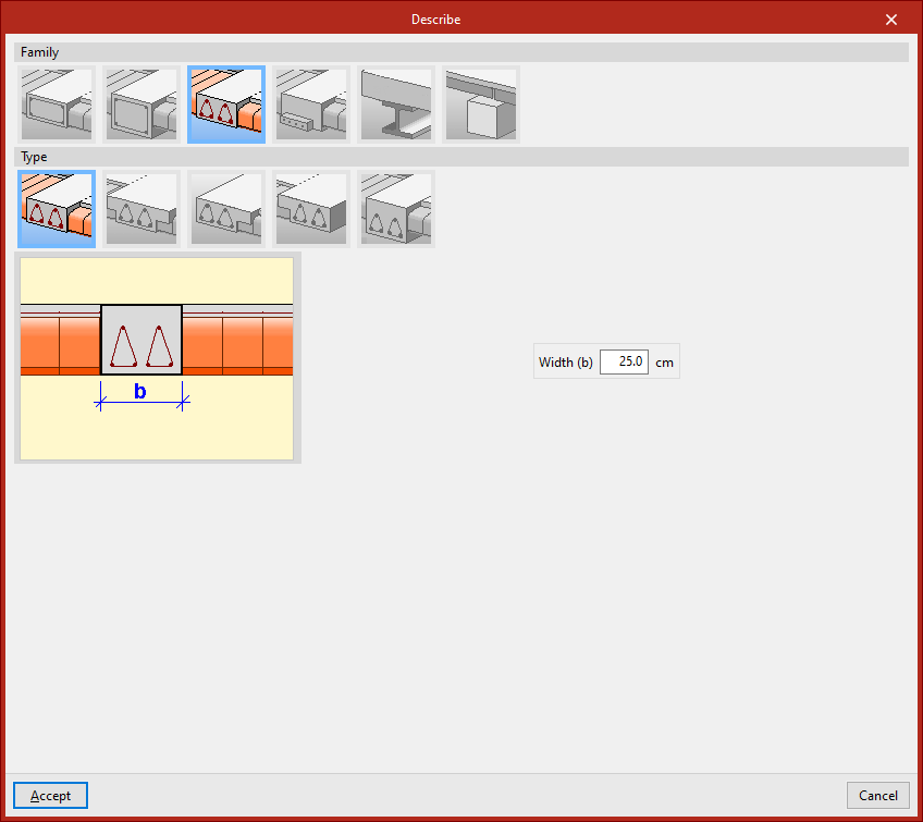
Lattice beams
"Lattice beams" are a type of beam with prefabricated reinforcement.
Their characteristics must be provided by the manufacturer and defined within the general project data (under the "Project" tab, options "General data", "Beams", "Options", "Reinforcement arrangement", "Lattice beams").
The available options include:
- Flat rectangular lattice beam
- Flat 'T' lattice beam
- Flat rectangular lattice beam with right flange
- Flat rectangular lattice beam with left flange
- Dropped rectangular lattice beam
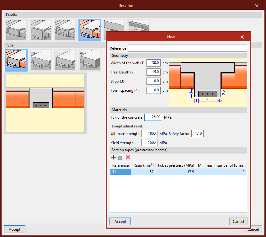
Prestressed beams
"Prestressed beams" have a prefabricated base and form their complete section during concreting together with the slab and the negative reinforcement placed in situ.
To define them, edit the prestressed beam library by clicking the corresponding button. Select "New", then define the "Reference", "Geometry", and the characteristics of the "Materials", both for the concrete and the longitudinal reinforcement, and add the available "Section types".
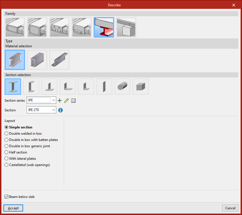
Steel beams
Within the "Steel beams" family, the following beams are available: "Rolled steel section", "Built-up section with rolled steel plates", and "Cold-formed steel section".
After selecting the material, you can configure the "Section selection" panel, which allows you to choose from a variety of available sections.
You can indicate that it is a "Beam below slab" by ticking the checkbox at the bottom.
Timber beams
The "Timber beams" family allows for the use of beams made of this material.
The section geometry of timber beams is defined using the libraries located next to the "Section series" and "Section" dropdowns.
The "Beam below slab" checkbox allows you to indicate this situation.
Inserting the beam in the model
A beam is defined by its start and end nodes, so two points must be selected using the left mouse button. By clicking again with the left button, you can continue inserting more beams.
To finish, right-click. At that moment, the program will create a continuous beam from all inserted elements, if possible.
A beam cannot be completely vertical. Moreover, the angle between its local XZ plane and the vertical plane it lies in must be zero. That is, no rotation about the longitudinal axis of the beam can be inserted.
A beam does not need to belong to a level, but if a level is defined, the beam will be assigned to the nearest lower level.
Inserting beams using the "Bar" option
Beams can also be inserted using the "Bar" option from the "Bars" group. Then, click the central edit button and in the "Type of structural element" section, select "Beam".
After clicking "Accept", the points that define the beam geometry are inserted as described above.
Description of the bar sections
The following tool, available in the "Bars" group of the top toolbar, under the "Geometry" tab (in the "Structure" tab), allows you to modify the section description of the bars:

Section
This option allows you to modify the structural element type, material, and section geometry for a group of bars. To do this, after clicking the option, bars are selected individually using the left mouse button or by drawing a selection area.
Right-clicking opens the "Describe" window. This window can also be accessed when inserting a new bar, by clicking the edit button in the "Properties – New bar" window.
This window allows you to edit the following information:
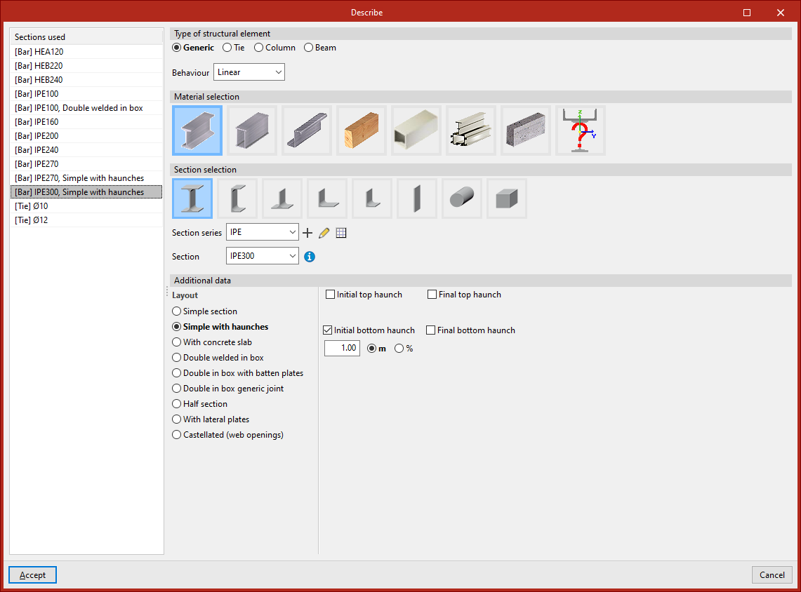
Sections used
On the left-hand side, the program displays the "Sections used" from other bars in the model, so they can be selected directly.
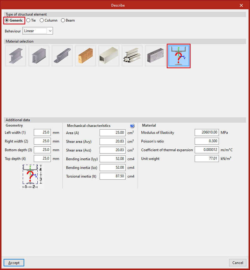
Type of structural element
On the right-hand side, in the "Type of structural element" section, you define whether the element is "Generic", a "Tie", a "Column", or a "Beam".If the element is "Generic", you can choose from the dropdown whether its "Behaviour" is "Linear" or "Only tension", and in this case you can define and insert a "Prestressing stress" by ticking the corresponding checkbox.
Material selection
In the case of a "Generic" element, under the "Material selection" section, you specify the material of the bar from the following options:
- Rolled steel section
- Welded steel plate section
- Cold-formed steel section
- Timber section
- Extruded aluminium section
- Special aluminium section
- Concrete bar
- Generic section
The last option is used to define a material that is not included in the above options.
Section selection
Next, the "Section selection" is carried out within the categories offered by the program for each material.
For example, within rolled steel sections, the following options are available:
- Rolled I
- C
- T
- Symmetrical angle
- Angle
- Plate
- Round bar
- Square bar
Clicking on the desired option allows the rest of the section parameters to be defined.From the dropdowns, the program allows you to select a "Section series" and a "Section" within that series.
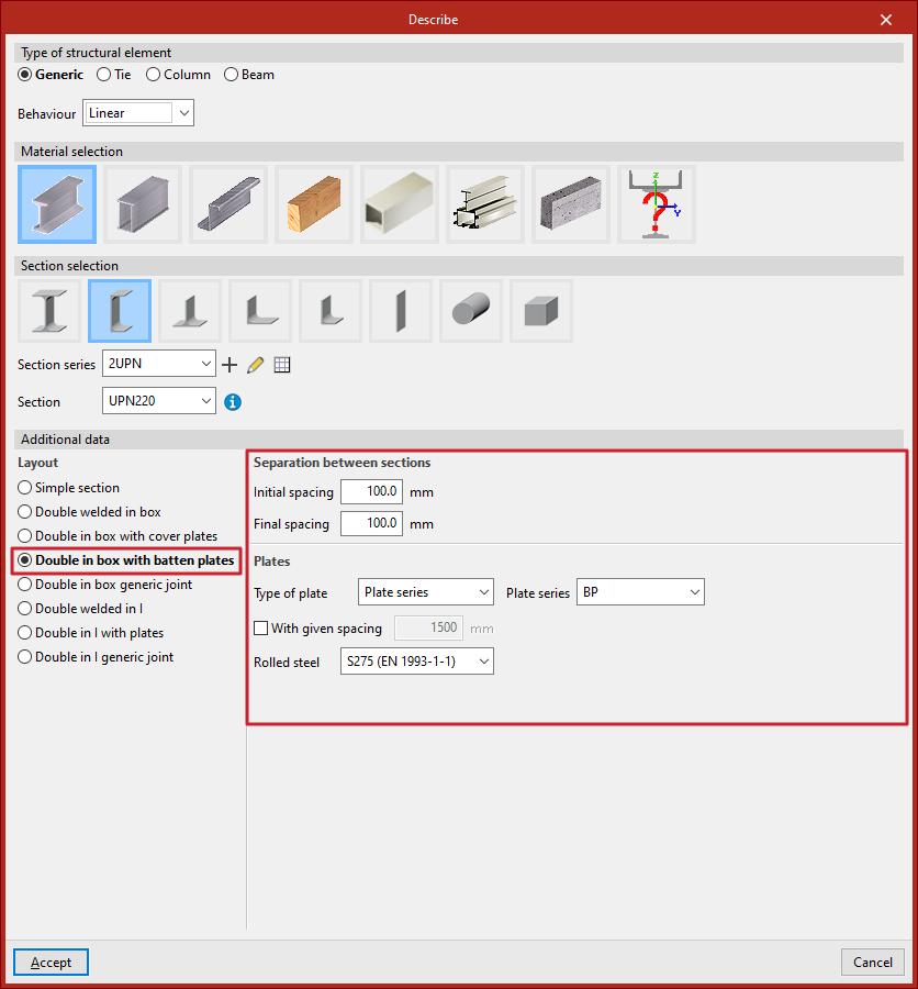
Additional data
In the "Additional data" section at the bottom, the "Section arrangement" is specified from the possibilities offered by the program for the selected section type.
For example, in the case of double T sections, the following options are available:
- Simple section
- Single with haunches
- With concrete slab
- Double in box with batten plates
- Double in box generic joint
- Half section
- With lateral plates
- Castellated (web openings)
When any of these options is selected, you must enter the required data and parameters, such as the dimensions of the stiffeners or the spacing between sections.
When clicking "Accept" in the "Describe" window, the program applies the chosen configuration to the selected bars.
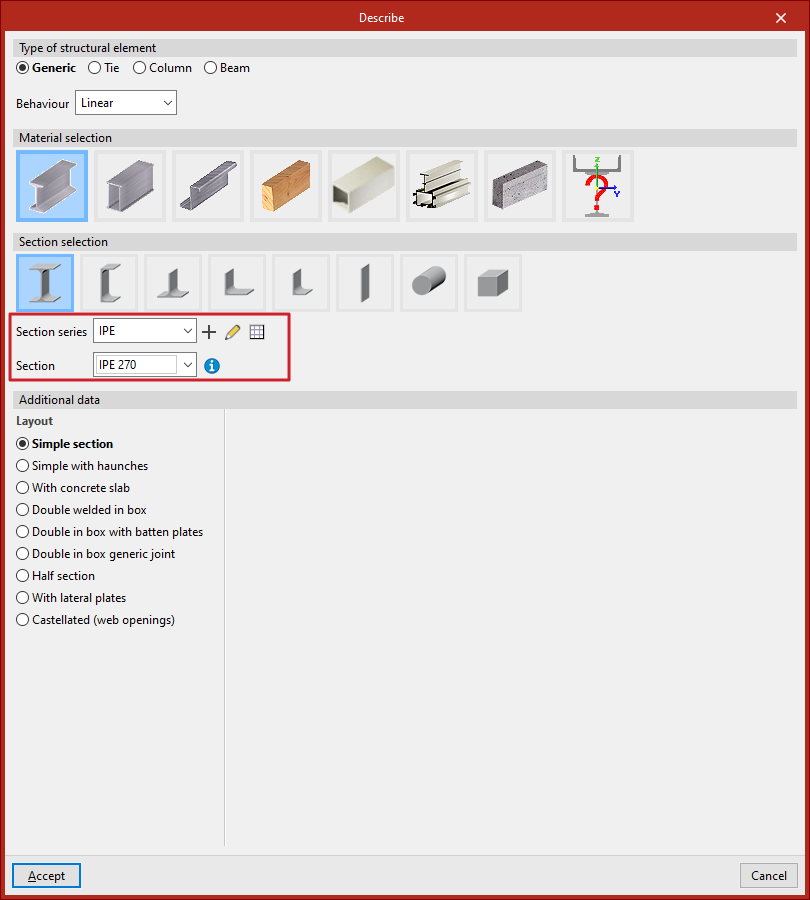
Managing section series
The section selection is carried out in the program using the drop-down menus "Section series" and "Section", which appear in certain sections of the "Describe" window, accessible both when entering a new section and when editing the section of an existing section.
A section series must be selected in the first drop-down menu, followed by a specific section from that series in the second drop-down menu.
Series can be created and edited using the buttons to the right of the first drop-down menu:
- To create a series, use the "New" option.
- If any existing section series is selected, you can make modifications to it using the "Edit selected type" button.
- Further to the right, the "Edit item list" option provides access to the "Section series" list.
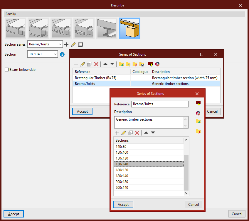
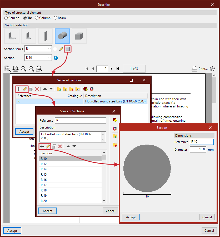
Series of sections list
This table allows for the management, import, and export of created series.
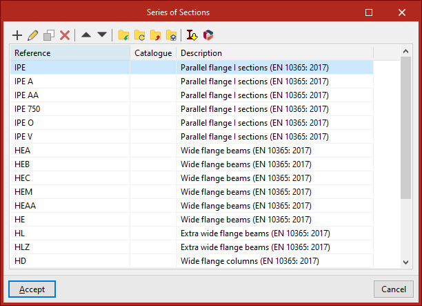
Series of sections
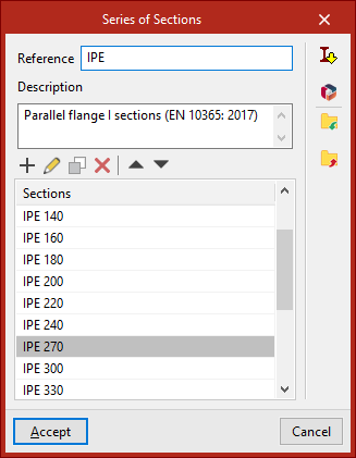
To create a section series, use the "New" option from either the "Describe" window or the section series list.
In the window that appears, enter a "Reference" and a "Description" for the series.
In the lower table, sections can be "Added", "Edited", "Copied", and "Deleted" from the series using the corresponding tools.
On the right, there are also utilities to "Import" and "Export" series to files on disk.
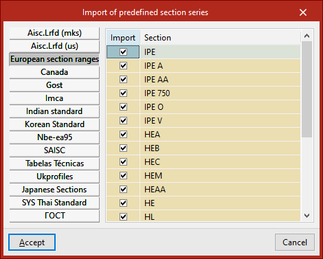
Importing predefined series of sections
On the right-hand side of the section series list and in the editing window for a specific section series, there is an option to perform the "Import of predefined section series" taken from various handbooks and standards.
After selecting the desired predefined series and clicking "Accept", the selected series will be added to the section series list, or the sections from the chosen predefined series will be imported into the section list of the series currently being edited.
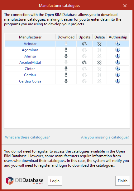
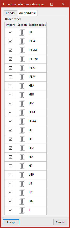
Importing section series from manufacturer catalogues
Also on the right-hand side of the section series list and in the editing window for a specific section series, it is possible to "Import manufacturer catalogues" via connection with Open BIM Database.
After downloading the catalogues, in the next window, select the series to be imported from each manufacturer. On clicking "Accept", the selected series will be added to the section series list, or the sections from the selected series will be imported into the section list of the series currently being edited.
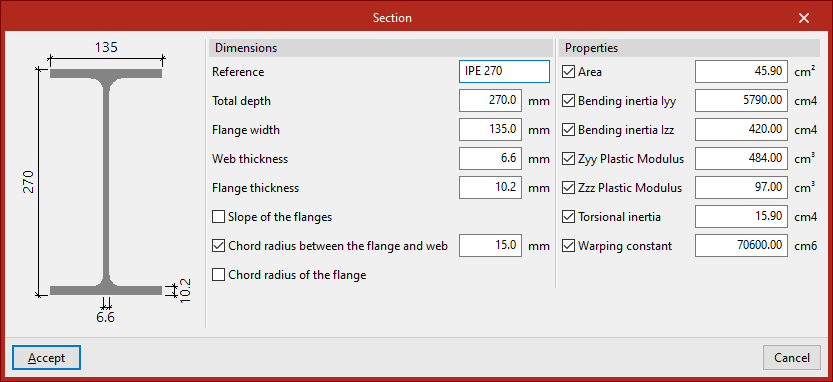
Section dimensions and properties
In the "Series of sections" window, when adding a "Section", a pop-up window appears.
In the central part of this window, the "Dimensions" of the section can be specified, such as the depth and the thicknesses of the web and flange.
On the right, the "Properties" of the section can be overridden by activating the following checkboxes:
- Area
- Bending inertia Iyy
- Bending inertia Izz
- ZyyPlastic modulus
- Zzz Plastic modulus
- Torsional inertia
- Warping constant
If left deactivated, the program will calculate these properties based on the defined dimensions.
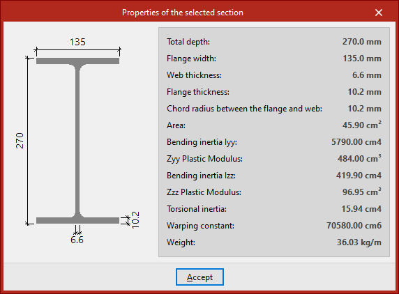
In the "Describe" window, after selecting a series and a section, the "Selected section properties" can be viewed using the button to the right of the second drop-down menu.
Available sections and layouts
The program offers the following sections and layouts for each material within the "Describe" window, which can be accessed when adding a new bar or via the "Section" option in the "Bars" group on the top toolbar of the "Geometry" tab (under the "Structure" tab).
Rolled steel sections

| Layout/Section | I beam | C section | T section | Symmetrical angle | Angular | Plate | Round bar | Square bar |
| Simple section | ✓ | ✓ | ✓ | ✓ | ✓ | ✓ | ✓ | ✓ |
| Simple with hauches | ✓ | |||||||
| With concrete slab | ✓ | |||||||
| Double welded in box | ✓ | ✓ | ||||||
| Double in box with batten plates | ✓ | ✓ | ||||||
| Double in box generic joint | ✓ | ✓ | ||||||
| Double welded in I | ✓ | |||||||
| I-shaped double with loops | ✓ | |||||||
| Double in a generic union | ✓ | |||||||
| Double welded in T | ✓ | |||||||
| Double in T generic joint | ✓ | |||||||
| Double in U generic joint | ✓ | |||||||
| Four in box generic joint | ✓ | |||||||
| Four in cross generic joint | ✓ | |||||||
| Four in I generic joint | ✓ | |||||||
| Half-section | ✓ | |||||||
| With lateral plates | ✓ | |||||||
| Castellated (web openings) | ✓ |
Roll-formed steel sections

| Layout/Section | Symmetrical welded I | Welded I of different flanges | I with variable depth | I-beam, different flanges, with variable depth | Simple welded C | Simple welded T | Square cold-formed box | Rectangular cold-formed box | Circular hollow section | Rectangular hollow section | Plate |
| Simple section | ✓ | ✓ | ✓ | ✓ | ✓ | ✓ | ✓ | ✓ | ✓ | ✓ | |
| With a concrete slab | ✓ | ||||||||||
| Double with generic join | ✓ | ✓ | ✓ | ||||||||
| Quadruple with generic join | ✓ | ✓ | ✓ | ||||||||
| Metal tube | ✓ |
Cold-formed steel sections
Table 1/2:

| Layout/Section | Circular hollow section | Square cold-formed box | Stiffened cold-formed C | Simple cold-formed Z | Simple cold-formed Omega | Stiffened Omega sloped webs | Symmetrical cold-formed angle | Symmetrical stiffened cold-formed angle |
| Simple section | ✓ | ✓ | ✓ | ✓ | ✓ | ✓ | ✓ | ✓ |
| Double with generic joint | ✓ | |||||||
| Four with generic joint | ✓ | |||||||
| Double welded in box | ✓ | ✓ | ||||||
| Double in box with batten plates | ✓ | |||||||
| Double in box generic joint | ✓ | ✓ | ||||||
| Double welded in I | ✓ | |||||||
| Double in I with plates | ✓ | |||||||
| Double in I generic joint | ✓ | |||||||
| Double welded in T | ✓ | ✓ | ||||||
| Double in T generic joint | ✓ | ✓ | ||||||
| Double in U generic joint | ✓ | ✓ | ||||||
| Double in cross generic joint | ✓ | ✓ |
Table 2/2:

| Layout/Section | Rectangular cold-formed box | Simple cold-formed C | Channel with stiffened web | Cold-formed Z with stiffeners | Simple Omega sloped webs | Omega sloped in external depth | Cold-formed angle | Stiffened cold-formed angle |
| Simple section | ✓ | ✓ | ✓ | ✓ | ✓ | ✓ | ✓ | ✓ |
| Double with generic joint | ✓ | |||||||
| Four with generic joint | ✓ | |||||||
| Double welded in box | ✓ | ✓ | ✓ | |||||
| Double in box with cover plates | ✓ | |||||||
| Double in box with batten plates | ✓ | ✓ | ||||||
| Double in box generic joint | ✓ | ✓ | ✓ | |||||
| Double welded in I | ✓ | ✓ | ||||||
| Double in I with plates | ✓ | ✓ | ||||||
| Double in I generic joint | ✓ | ✓ | ||||||
| Double welded in T | ✓ | ✓ | ||||||
| Double in T generic joint | ✓ | ✓ | ||||||
| Double in U generic joint | ✓ | ✓ | ||||||
| Double in cross generic joint | ✓ | ✓ |
Timber sections

| Layout/Section | Round bar | Square bar | Rectangular bar | Rectangular, variable depth |
| Simple section | ✓ | ✓ | ✓ | ✓ |
Extruded aluminium sections

| Layout/Section | I beam | C section | T section | Symmetrical angle | Angular | Plate | Rectangular hollow section | Circular hollow section | Round bar | Square bar |
| Simple section | ✓ | ✓ | ✓ | ✓ | ✓ | ✓ | ✓ | ✓ | ✓ | ✓ |
Standard concrete beam
| Section type | Circular | Rectangular | Rectangular with variable depth |
| Concrete beam | ✓ | ✓ | ✓ |
Ties

| Section | Symmetrical angle | Angular | Plate | Round bar | Square bar |
| Tie | ✓ | ✓ | ✓ | ✓ | ✓ |
Selecting and defining sections with batten plates
Sections with batten plates are selected and defined in the "Describe" window, which can be accessed when adding a new beam or via the "Section" option in the "Beams" group on the top toolbar of the "Geometry" tab (under the "Structure" tab).
The program allows you to use sections with plates in the following materials, sections and configurations:
- Rolled or welded steel section
- I beam
- Double in box with batten plates
- C section
- Double in box with batten plates, Double in I with plates
- I beam
- Cold-formed steel section
- Stiffened cold-formed C
- Double in box with batten plates, Double in I with plates
- Simple cold-formed C
- Double in box with batten plates, Double in I with plates
- Channel with stiffened web
- Double in box with batten plates, Double in I with plates
- Stiffened cold-formed C
In either case, you will need to specify the spacing between the sections and the details of the clips in the "Additional data" section:
Spacing between sections
In this section, you enter the "Initial spacing" and "Final spacing" between the sections. These values refer to the gap or separation distance between the closest faces of the sections at the start and end of the bar.
Batten plates
When specifying a connection using clips, the type of clip to be used, the cross-sectional area of each clip and the spacing between clips, as well as the material, must be specified:
- Type of plate
Allows you to choose from the following options to define the cross-section of the batten plate:- Generic plate
In this case, the program will calculate the entire geometry of the flange. - Plate series
In this case, the program allows you to select any of the rectangular rolled steel section series previously defined in the project (under "Rolled steel sections", "Plate") in order to position a specific bracket.
- Generic plate
- With given spacing (optional)
- If this option is enabled, the user specifies the distance between joints (or the centre-to-centre distance between batten plates). Depending on this distance and the selected design standard, the program will treat the section as a simple section, a composite section, or as separate bars if the maximum distance for it to be considered a composite section is exceeded.
- If this option is not selected, the program will calculate and assign the maximum distance between joints so that the structure can be treated as a composite section. This maximum distance depends on the selected design standard.
In the last drop-down menu, you must select the type of steel for the batten section.
The program will then allow you to view the data obtained from the analysis of the ties using the "Tie" option in the "Analysis" tab.
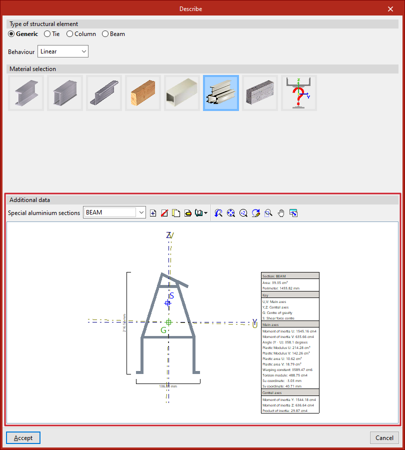
Defining special aluminium sections
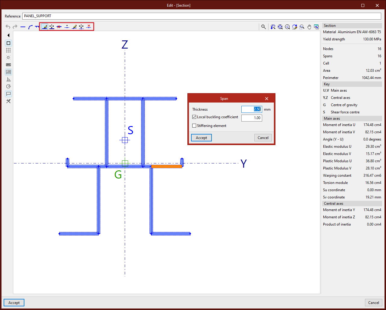
The program allows the use of special aluminium sections and lets you freely define their geometry by entering straight segments, curved segments, and elements with stiffeners through the following options.
Accessing the definition of special aluminium sections
Special aluminium sections are entered and edited using the "Section" option, available in the "Bars" group of the top toolbar, within the "Geometry" tab (on the "Structure" sheet).
Then, individual bars are selected using the left mouse button or by drawing a selection window. Right-clicking opens the "Describe" window.
This window can also be accessed when entering a new bar by clicking the edit button in the "Properties – New bar"window.
Here, the following options are selected:
- In the "Type of structural element" section, a "Generic" element is defined
- Then, in the "Material selection" section, "Special aluminium sections" is selected
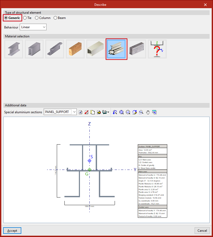
Special aluminium sections library
After selecting the indicated options, the program displays the "Additional data" of the section in the lower part of the "Describe" window. By default, the "Special aluminium sections" dropdown will be empty. On the right, you’ll find tools to "Create", "Delete", "Copy", and "Edit" sections.
From "Library management", you can "Import from library", "Export" to use in another project, "Edit the library", or define an "Initial import" for all projects.
Clicking on "Create", "Copy", or "Edit" opens the special aluminium section editor.
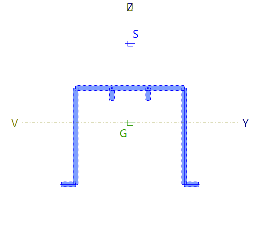
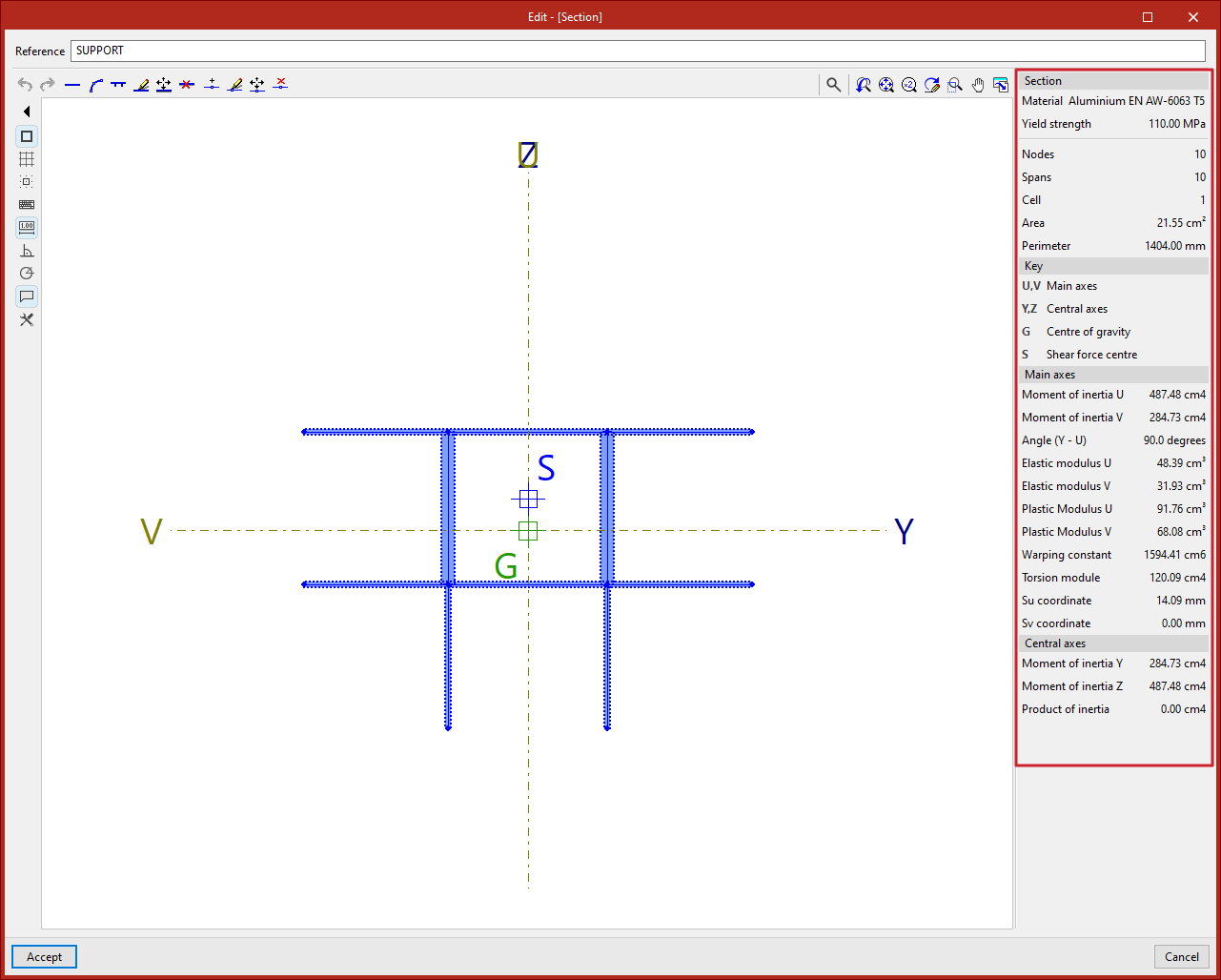
When a specific special aluminium section is defined and selected, the viewer at the bottom displays the drawn section, showing total width and height, the location of principal (U, V) and central (Y, Z) axes, the centre of gravity (G), and the shear centre (S). A table on the right shows the main characteristics of the section.
Special aluminium section editor
In the special aluminium section editor, the first step is to enter a "Reference" for the section.
Below that, in the central viewer, the section is drawn. This viewer offers:
- options to enter the segments that make up the section in the top left, next to undo and redo options (1);
- auxiliary drawing tools, in the left column (2);
- and screen visualisation tools, in the top right corner (3).
On the right side, the program dynamically displays and updates the data of the defined section.
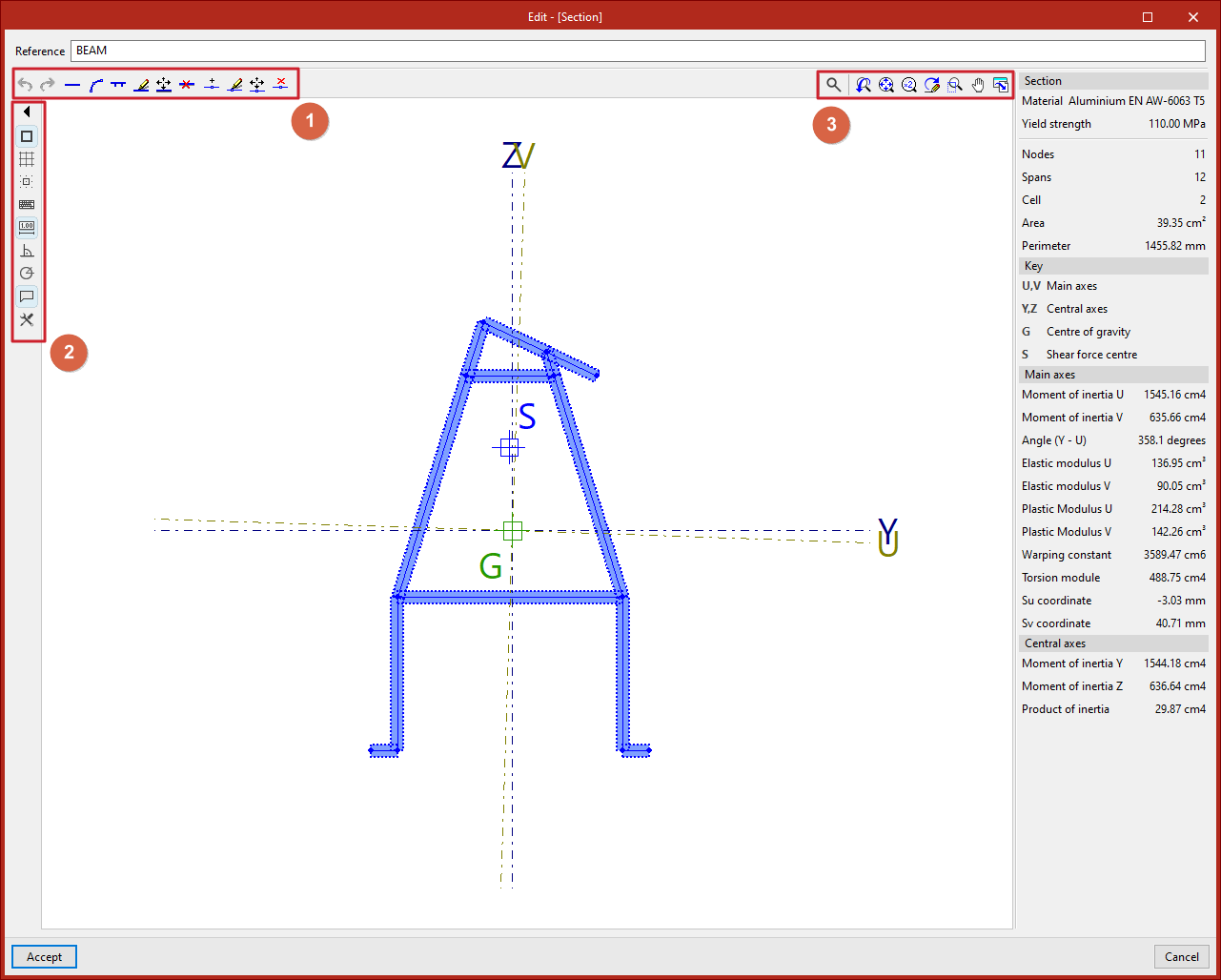
To enter the segments that define the section, the program offers a set of tools at the top left of the viewer:
Entering straight segments
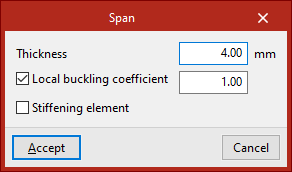
From the "New" button, one or more straight segments can be added. The program allows specifying a "Thickness" in the units defined in the project, activating and entering the "Local buckling coefficient", and indicating whether it is a "Stiffening element".
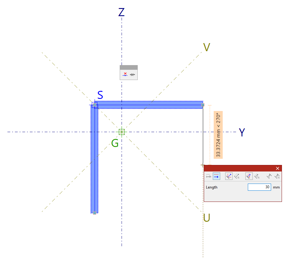
After clicking "Accept", left-click in the viewer to place the segments. Multiple segments can be entered by clicking in several points.
Additionally, the pop-up panel provides options to "Delete last entered point" and "Delete all entered points".
When finished, right-click to end the input.
| Note: |
|---|
| Sections with multiple disconnected parts cannot be defined. |
Entering curved segments
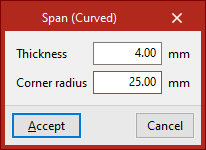
To enter a curved segment, click on the "New (Curved)" option. In this case, the "Thickness" and "Corner radius" must be defined.
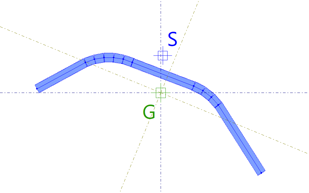
Then, two points are entered in the viewer to define the curved segment.
The program draws a polyline of successive straight segments approximating the curve using the given radius.
| Note: |
|---|
| Curved elements cannot have any free edges. |
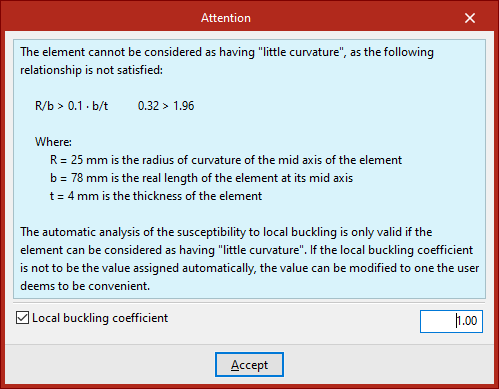
When drawing a curved element, a warning will appear if it cannot be considered "slightly curved", due to not meeting the geometric ratio shown in the warning.
The validity of the automatic local buckling susceptibility analysis depends on whether the element can be considered "slightly curved".
If you do not wish to use the automatically assigned local buckling coefficient, you can modify it as needed by enabling the "Local buckling coefficient" checkbox at the bottom of the warning.
Entering flat elements reinforced with stiffeners
The next option, "New (Stiffener)", allows you to enter a flat element reinforced with stiffeners.
First, the "Thickness" is defined.
Then, specify the "Type of reinforced flat element" and the "Type of simple stiffening" associated:
- If a "Flat external element with end flange or bulb" is defined, the stiffener can be standard, trapezoidal bulb, circular bulb, or generic.
- If a "Flat internal element with a central longitudinal stiffener" or a "Flat internal element with two equally spaced longitudinal stiffeners" is defined, the stiffener can be standard, trapezoidal, or generic.
En la parte inferior se escriben los pIn the lower part, parameters defining the stiffener geometry are entered. For a "Generic stiffener", the "Moment of inertia with respect to axis s" is defined.
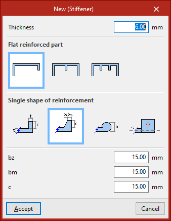
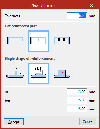
After clicking "Accept", left-click two points to place the segment.
A flat element with one or two stiffeners will be generated automatically, depending on the selected options.
Special aluminium section editing tools
The remaining options in the top bar allow you to modify the entered geometry:
- With "Edit", you can click on a segment and modify its properties.
- Using "Move", click the left mouse button on a node or segment to change its position.
- To "Delete" segments, after selecting the relevant option, use the left mouse button to select segments individually or define a selection area, then right-click to delete them.
- You can also enter a "New" node. In this case, indicate whether it is a "Longitudinal weld" or not, then click a point on a segment to add it.
- If you want to modify a node’s characteristics, after selecting "Edit", left-click the node to select it.
- With the next option, you can "Move" nodes by left-clicking and defining their final position.
- Using "Delete", nodes can be selected individually or by area, then deleted with a right-click. In this case, associated segments will also be removed.
Auxiliary tools in the viewer
During the segment input process, you can use "Snaps", activated in the left panel, along with other tools in the viewer's left column.
With "Show information texts" activated, moving the pointer over segments and defining nodes displays information about them.
Using the mouse wheel in the viewer allows zooming. Pressing and dragging the wheel or middle mouse button pans the image.
The tools in the top right corner of the viewer also allow these actions and are common across other program viewers.
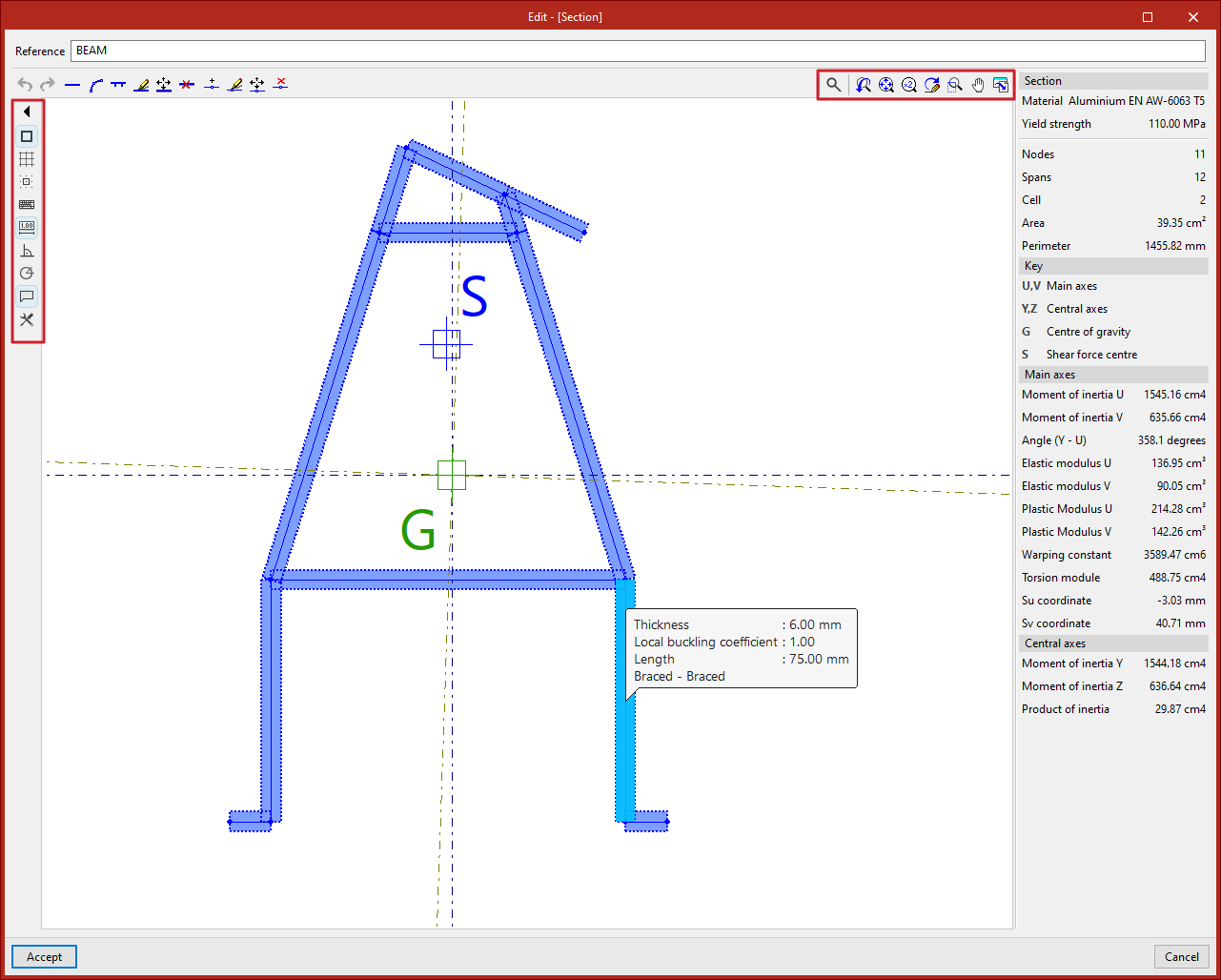
Special aluminium section data
On the right panel, the program automatically displays analysed data for the entered "Section", such as the number of "Nodes", "Segments", and "Cells", along with "Area" and "Perimeter".
Below this, you’ll find the "Legend". The program shows the principal axes U and V and the central axes Y and Z of the section.
It also shows the "Centre of gravity" G and the "Shear centre" S.
At the bottom, various calculated values related to the principal and central axes of the section are listed, including moments of inertia, elastic moduli, and plastic moduli.
Finally, by clicking "Accept", you exit the section editor and return to the "Describe" window.
Clicking "Accept" again applies the defined section to the selected group of bars.
Defining generic sections
The program allows you to use generic sections to simulate sections not available in the other options of the program. Additionally, you can define a generic material by entering its properties. The following options are used for this purpose.
Accessing the definition of generic sections
Generic sections are carried out using the "Section" option, available in the "Bars" group of the top toolbar, under the "Geometry" tab (within the "Structure" pane).
After selecting the bars, right-clicking opens the "Describe" window.
This window can also be accessed when entering a new bar by clicking the edit button in the "Properties – New bar" window.
Here, the following options are selected:
- In the "Type of structural element" section, select "Generic".
- Then, in the "Material selection" section, choose "Generic section".
Defining the geometry, mechanical characteristics, and material of the generic section
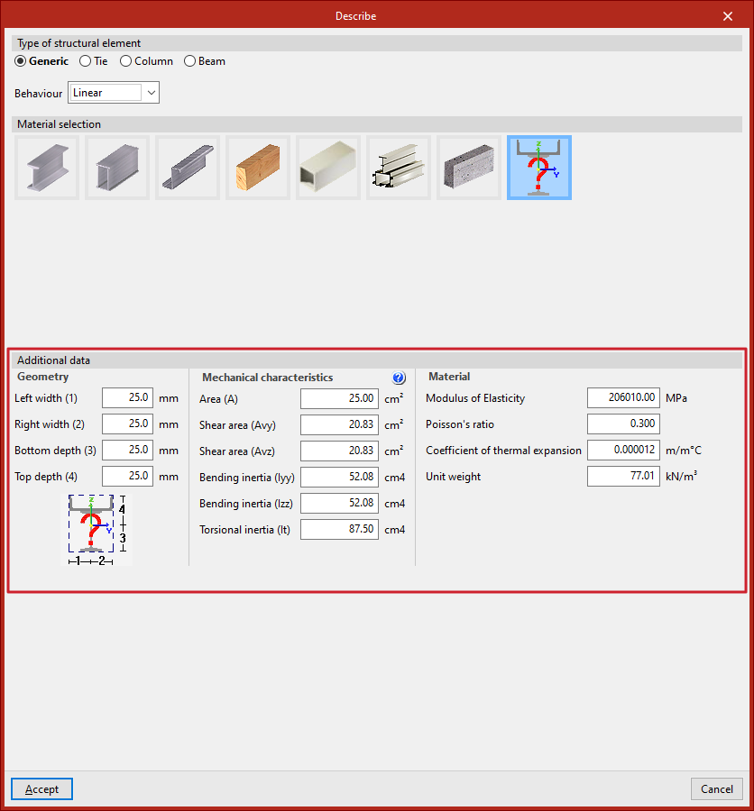
In the lower panel, "Additional data", the characteristics of the section are specified.
First, define the "Geometry" of the section envelope by specifying:
- The "Left width"
- The "Right width"
- The "Bottom depth"
- The "Top depth"
These dimensions are referenced to the local coordinate centre, as shown in the diagram at the bottom.
Next, enter the "Mechanical characteristics" of the section. In the cross-section, it is assumed that the principal inertia axes coincide with the local Y and Z axes. Here, input:
- The total "Area" of the section (A)
- The "Shear area" in both directions (Avy, Avz)
- The "Bending inertia" in both directions (Iyy, Izz)
- The "Torsional inertia" (It)
Finally, the "Material" data can be specified by entering:
- The "Modulus of Elasticity"
- The "Poisson’s ratio"
- The "Coefficient of thermal expansion"
- The "Unit weight"
When clicking "Accept", the program will apply the defined section to the selected set of bars.
Analysing generic sections
After the analysis, the program will provide internal forces and displacements for the bars defined with generic sections. However, it is not possible to carry out strength checks or to design these sections.
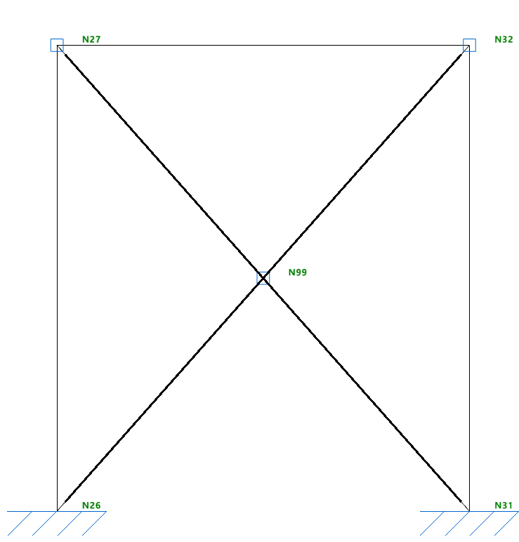
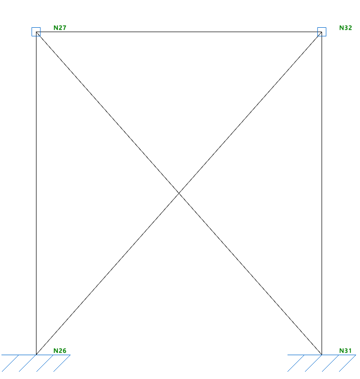
Entering ties
The program allows you to enter ties, that is, pin-ended straight-axis bars that only resist axial tensile forces along their axis, using the following options.
Ties inserted in this way are designed using a specific method outlined below and can only be defined within braced panels.
Accessing the definition of ties
Ties are defined either when inserting a new bar (using the "New" option) or by editing an existing bar via the "Section" option.
Both options are available in the "Bars" group on the top toolbar, under the "Geometry" tab (within the "Structure" tab).
In the "Describe" window, in the upper "Type of structural element" section, select "Tie".
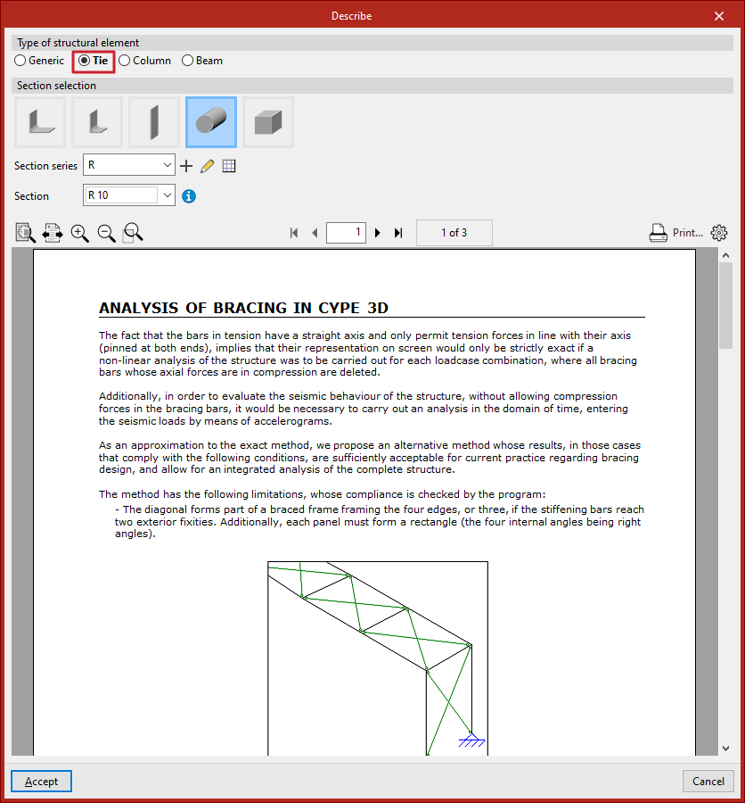
Selecting the tie section
Next, carry out the "Section selection" from the categories offered by the program:
- Symmetrical angle
- Angle
- Plate
- Round bar
- Square bar
Subsequently, the drop-down menus allow you to select the "Series of sections" and the "Section" within that series.
As with "Generic" sections, you can create and edit a series of sections using the buttons located to the right.
Analysing ties
At the bottom of the "Describe" window, a help text related to "Analysis of bracing in CYPE 3D" is displayed. It explains the methodology used by the program to analyse these elements and outlines their limitations.
Placing ties in the model
After configuring the tie section in the "Describe" window, click "Accept" to insert it into the workspace.
The tie is defined by its start and end nodes. To insert it into the model, select two points with the left mouse button. To confirm the insertion of the tie, click the right mouse button.
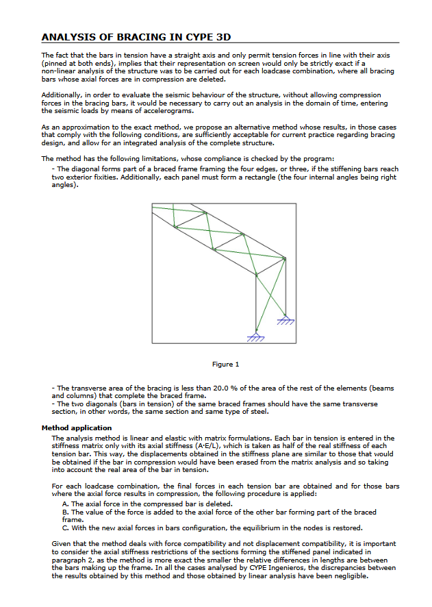
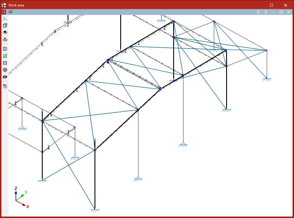
Ties must form part of a braced panel arranged in the shape of a Saint Andrew’s cross.
This panel must be framed at its edges by four bars located in the same plane and forming a rectangle, meaning all four internal angles must be right angles.
It is also possible to define the perimeter of a braced panel using only three bars if the end of two of them is stiffened by an "External fixity", such as in a portal frame formed by two vertical bars connected by a horizontal beam.
The two diagonals of a braced panel must be made of the same material and have the same cross-section. Additionally, the cross-sectional area of the ties must be less than 20% of the area of the other elements forming the perimeter of the panel.
Finally, it is advisable to ensure that when inserting ties within the same panel, the "Generate nodes at intersection points" option from the "Bars" group in the "Geometry" tab remains deactivated, as the elements must remain independent of each other.
Editing bar material
The editing of bar material is carried out using the following tool, available in the "Bars" group on the top toolbar, within the "Geometry" tab (in the "Structure" tab).

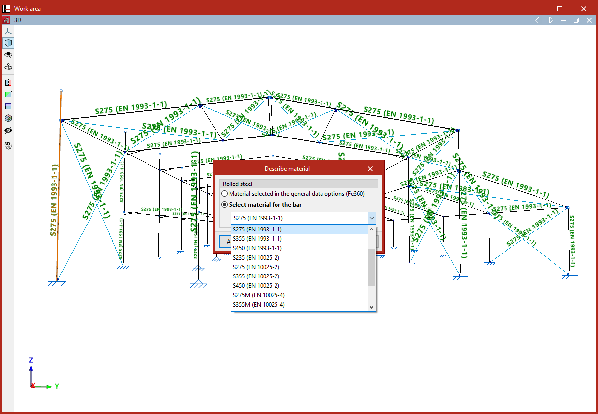
Material
This option allows you to select the material for a group of bars.
After selecting the bars, right-click.
In the pop-up window, you can choose to keep the "Material selected in the general data options" or "Select material for the bar" specifically from the options available in the dropdown menu.
By clicking "Accept", the selected material is applied to the bars.
Description of bar layout
The description of the bar layout is carried out using the following tool, available in the "Bars" group on the top toolbar, within the "Geometry" tab (under the "Structure" section).

Layout
After clicking on the "Layout" option, bars are selected individually with the left mouse button or by drawing a selection area.
Then, right-click. In the window that appears, the layout of the bar’s cross-section can be defined in relation to the line entered in the model.
In the first section, "Analysis", you can specify whether to "Consider eccentricities in the analysis" by ticking the corresponding checkbox. If this option is not enabled, the bar will be considered centred in the design model.
Next, the "Rotation angle" of the section is defined. It can be "0" degrees, "90" degrees, or a "Rotation angle" defined by the user with any value.
In the viewer on the right-hand side, the "Position" of the cross-section is shown relative to the local Y and Z coordinate axes, displayed in green and blue, respectively.
The reference point is marked with a red cross and is positioned at the centre of the section by default. You can click on the crosses located at the edges or corners of the section to modify the position of the reference point.On the left, under the section "Displacements in local axes", the displacement values of the section's reference point are entered relative to the coordinate system defined by the local axes of the element.
- If "Same at both ends" is selected, the displacement value can be entered for the local "Y" or "Z" axes. Doing so will display the position change of the section relative to the local coordinate axes in the viewer on the right.
- If "Different at either end" is selected, displacement values must be entered for both the "Start" and "End" of the member. In this case, the cross-section of the member is shown at both points in the right-hand viewer.
Next, under the section "Displacements in global axes", the "X", "Y", and "Z" coordinates of the ends of the element are specified in relation to its definition nodes within the global coordinate system.
Again, displacements can be "Same at both ends" or "Different at either end".
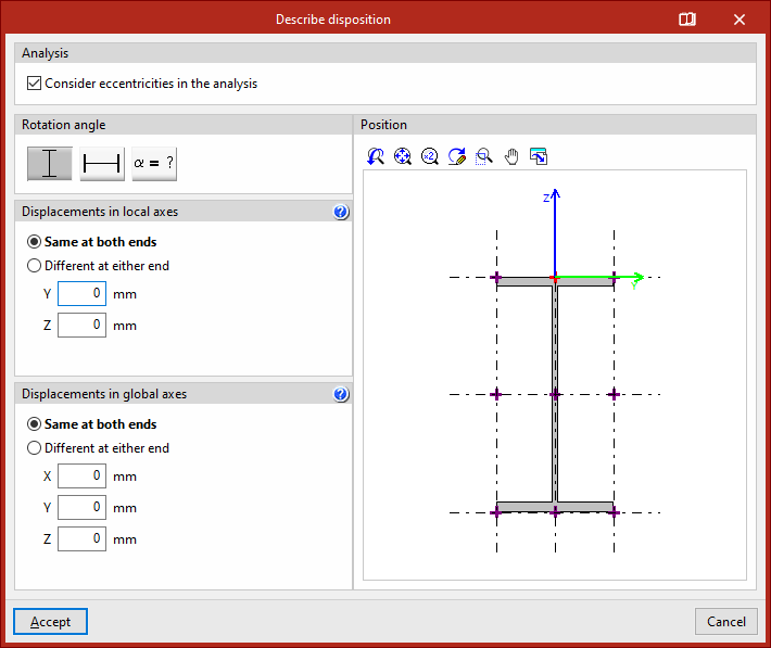
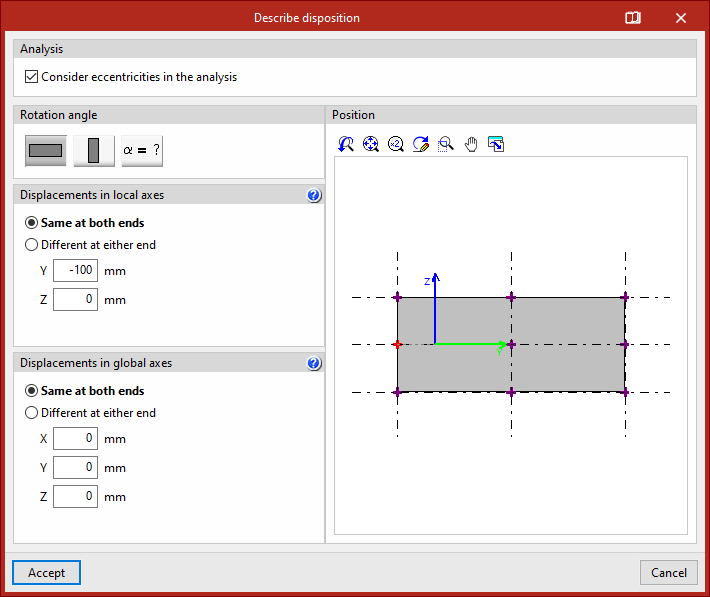
For more information about bar positioning and the sign conventions for global and local displacements, you can click on the corresponding button in the title bar of this window to consult the help provided by the program.
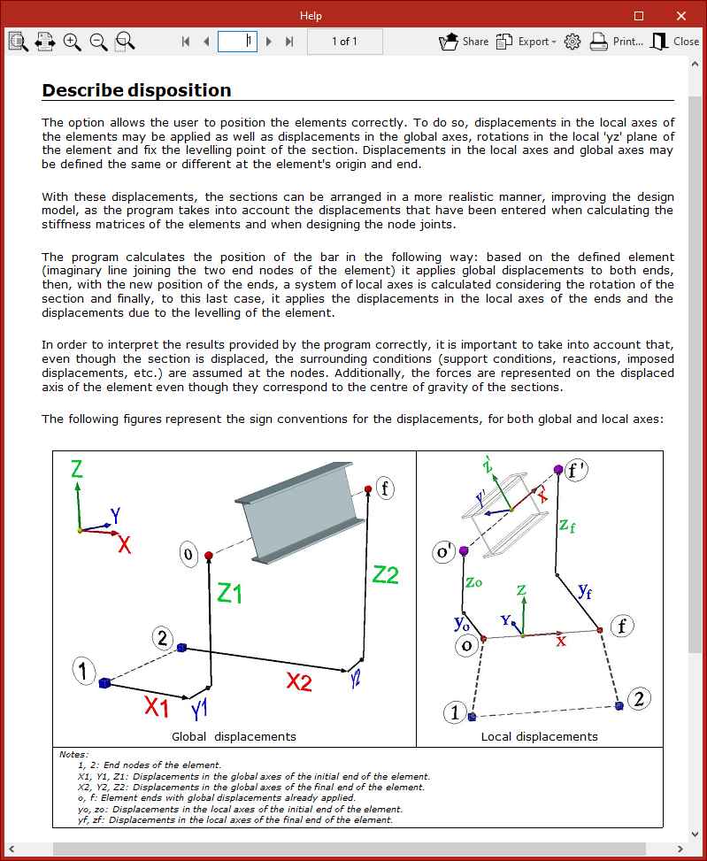
After modifying the bar layout in the workspace, the line entered in the model is shown as a continuous line (1), while the actual position of the bar's section axis is represented as a dashed or dash-dot line (2).
Move ends and invert the 'x' axis of bars
The program offers the following tools in the "bars" group of the top toolbar, within the "geometry" tab (in the "structure" tab).

Move end
The "move end" option allows you to change the position of one of the nodes at the ends of a bar.
To do this, click on the node and then on its new position.
This operation does not delete the node at the original end of the bar, which can still be used to continue working on the model.
Invert the direction of the 'x' axis
The "invert the 'x' axis" option allows you to invert the direction of the local X axis of the bars, thereby swapping the start and end of each bar. The local X axis is shown in red on each bar in the model when you hover over them.
After selecting the option, select the bars and right-click.
If fixity coefficients or loads have been defined, the program will automatically adjust their data so they are not affected by the inversion of the axis direction.
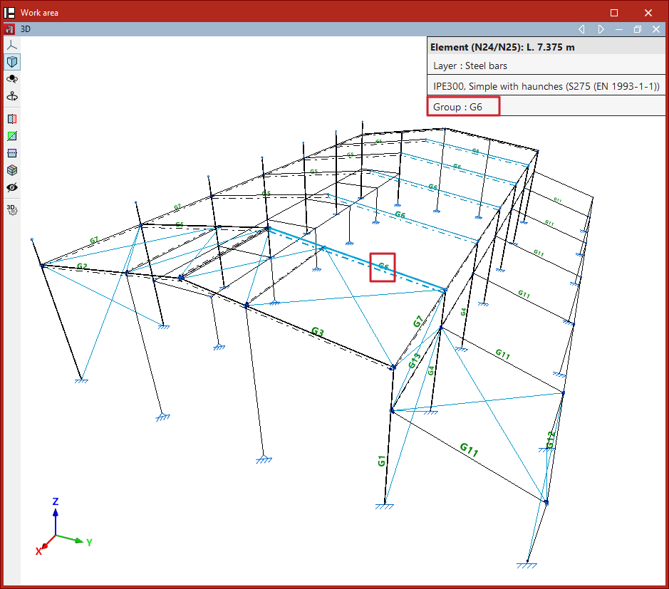
Grouping and ungrouping elements
The grouping and ungrouping of elements is carried out using the following tools, available in the "Bars" group of the top toolbar, under the "Geometry" tab (in the "Structure" tab).

Groups of elements will be assigned the same section and material, even as a result of the design process. Furthermore, the program will automatically modify all elements belonging to the same group when using the "Section" or "Material" options.
Grouping elements
To create a group of elements, click on the "Group" option, select two or more elements with the left mouse button, then right-click.
After confirming the operation in the dialogue box that appears, the program will group the elements.
Each group of elements has an associated reference for identification. This reference is displayed as text in the model, positioned above the bars.
Additionally, when hovering the mouse pointer over the elements, the program indicates the "Group" to which they belong in the information box.
Ungrouping elements
Use the "Ungroup" option to perform the reverse operation.
After selecting the sections you wish to ungroup, right-click on them.
The selected sections will no longer form part of the group, and from that point on, their description will be independent.
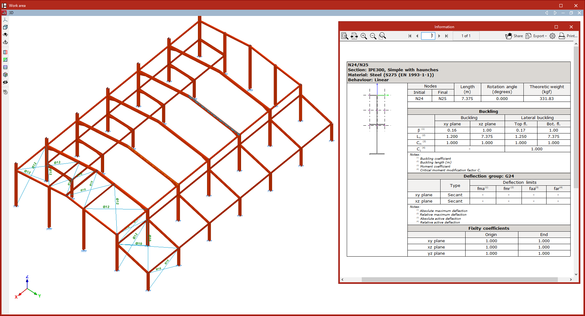
Checking bar information
The following tool, available in the "Bars" group of the top toolbar, under the "Geometry" tab (in the "Structure" tab), allows you to check the information about the bars.

Information
The "Information" option displays an information list of the selected bars.
To select the bars, click on them one by one with the left mouse button or define a capture area. Then, confirm with the right mouse button.
The program will display a list on screen showing the information for the bars. Each table in the list indicates the reference of each bar, its "Section" and "Material". On the left-hand side, the section and layout of the section are shown.
On the right-hand side, you will see the reference of the "Nodes" ("Start" and "End"), the "Length" of the bar, the "Rotation angle", the "Theoretical weight", the "Buckling" parameters, and the "Deflection group" it belongs to, as well as the "Fixity coefficients" in both planes.
Using the corresponding options at the top right, you can "Share", "Export" in various formats, or "Print" the information.
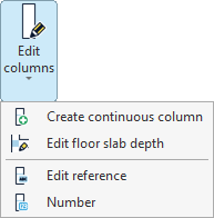
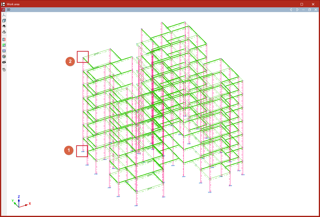
Editing columns
The "Edit columns" options are available in the corresponding menu within the "Bars" group of the top toolbar, under the "Geometry" tab (in the "Structure" section).

The options available in this menu are as follows:
- Create continuous column
- Edit floor slab depth
- Edit reference
- Number
Each of these functions is described below.
Create continuous column
The "Create continuous column" option allows you to describe a group of aligned elements between two nodes as a single column.
Select the starting node of the first element with the left mouse button, then select the final node of the last element to be included in the column.
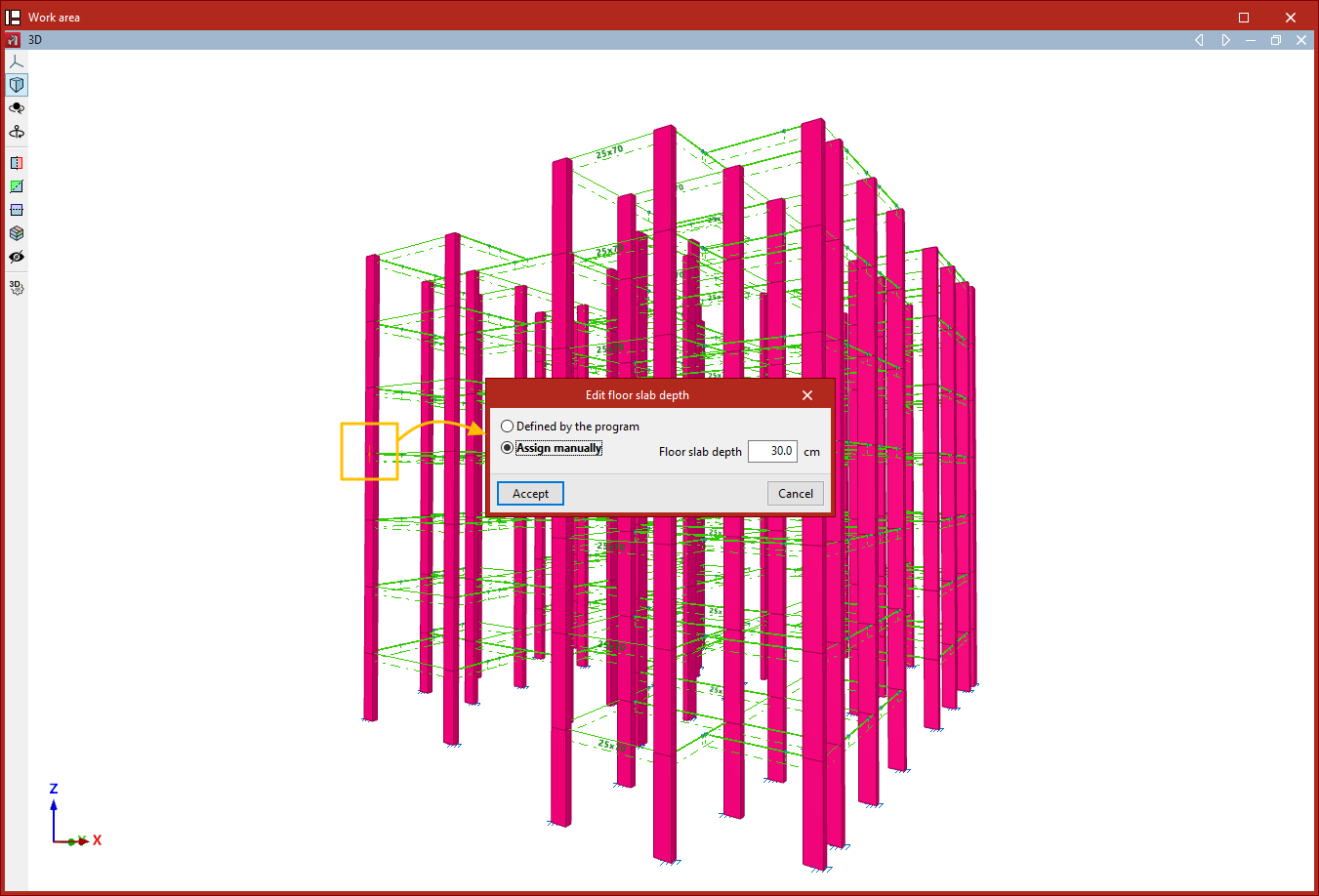
Edit floor slab depth
This option allows you to edit the slab depth at a node of a column, in case a depth different from the one automatically determined by the program is required. The slab depth defines the clear height of the column between two levels.
Nodes are selected with the left mouse button or by drawing a selection area, then the selection is confirmed with the right mouse button.
In the window that appears, you can specify whether the slab depth is "Determined by the program" or set it manually, in which case you must enter the value in the corresponding field. Then, click "Accept".
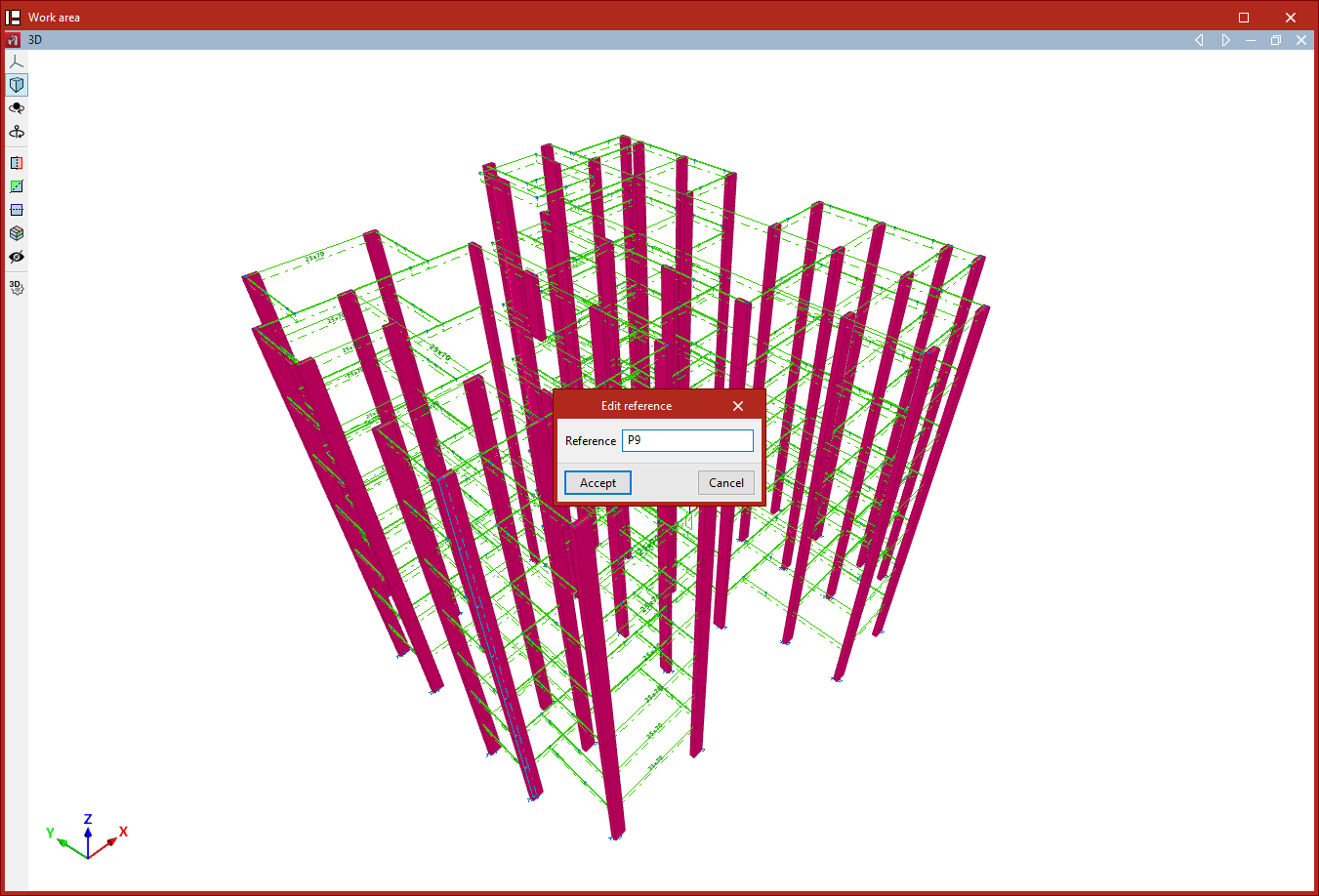
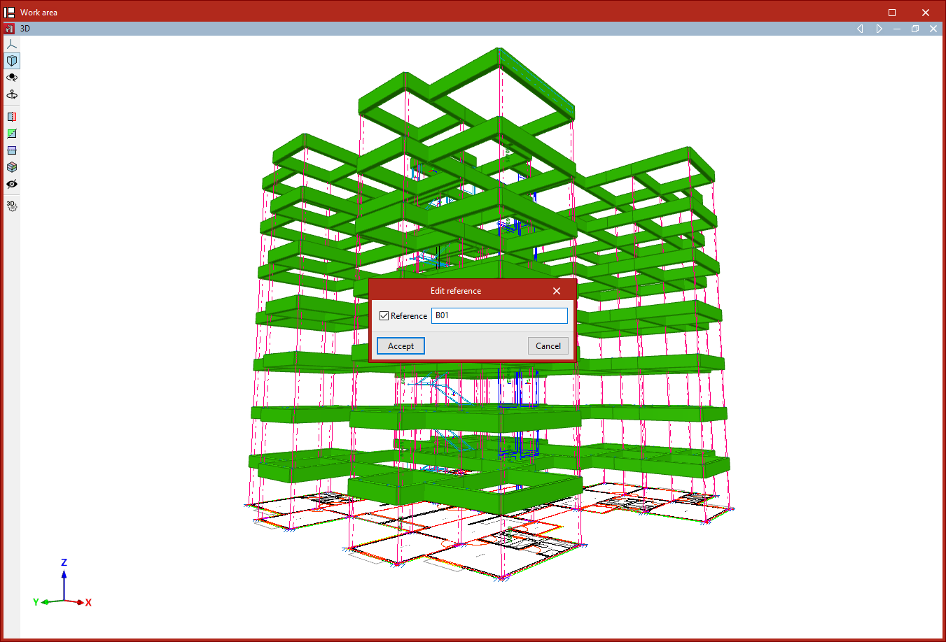
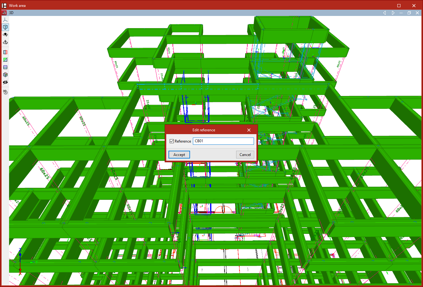
Edit reference
To edit a column's reference, select the corresponding option and then click on the column. After entering the new "Reference", click "Accept".
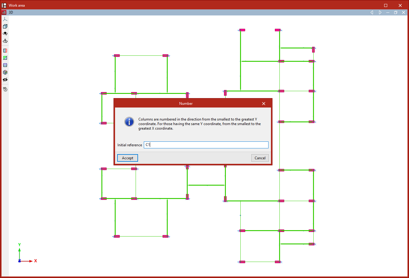
Number
This option allows you to "Number" all the columns in the project consecutively.
After clicking the option, the program displays a message: "Columns are numbered in the direction from the smallest to the greatest Y coordinate. For those having the same Y coordinate, from the smallest to the greatest X coordinate."
All of this is based on an "Initial reference", which must be entered. Then, click "Accept".
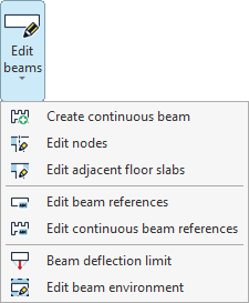
Beam editing
The "Beam editing" options are available in the corresponding menu of the "Bars" group on the top toolbar, within the "Geometry" tab (in the "Structure" tab).

The options available in this menu are as follows:
- Create continuous beam
- Edit nodes
- Edit adjacent floor slabs
- Edit beam references
- Edit continuous beam references
- Beam deflection limit
- Edit beam environment
Each of these features is detailed below.
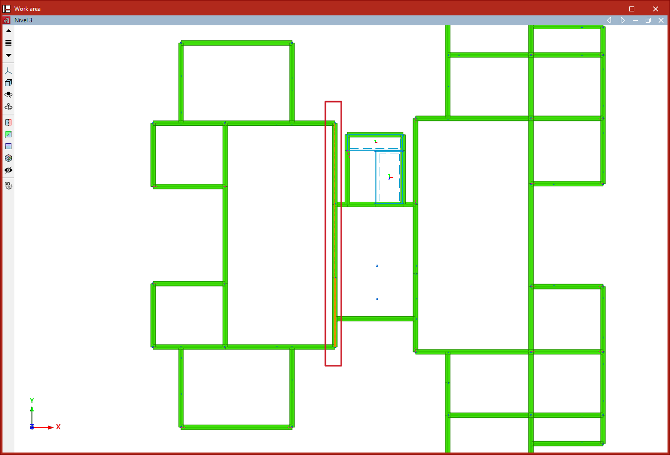
Create continuous beam
This option allows you to create a continuous beam. The beams that form the new continuous beam are selected using the left mouse button, then the right button is clicked.
The selected beams must be connected so that the end node of one beam is the start node of the next. In addition, all beams must be of the same material class, and the local XZ plane of each beam must lie in a vertical plane.
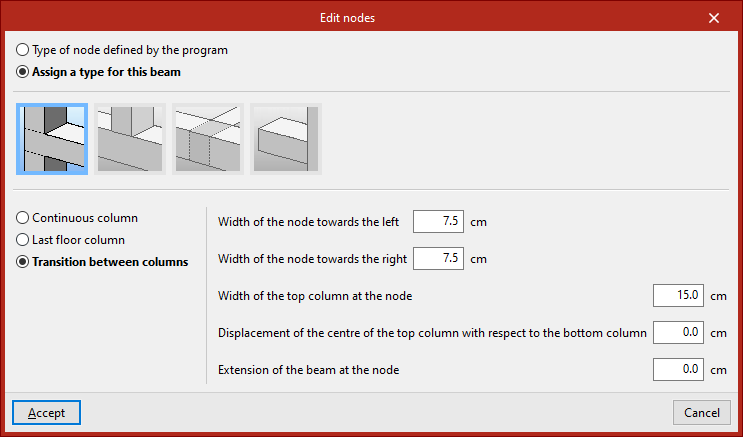
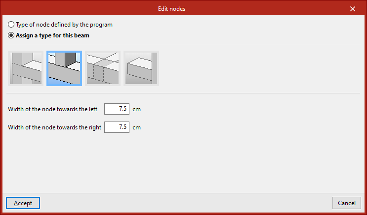
Edit nodes
The "Edit nodes" option allows you to edit the geometry of a node in a continuous beam, in case you want to use a geometry different from the one automatically determined by the program.
Nodes are selected with the left mouse button or by drawing a selection area, then the selection is confirmed with the right mouse button.
In the window that appears, you can keep the "Type of node defined by the program" or "Assign a type for this beam", indicating whether it is a "Column", "Short column", "Support on beam" or "Cantilever".
For each of these cases, parameters that define the node are specified in the lower section, such as "Width of the node towards the left" and "Width of the node towards the right".
The node geometry affects the clear span of the beams as shown in the beam reinforcement editor, and therefore the length of the reinforcement bars.
Then, click "Accept".
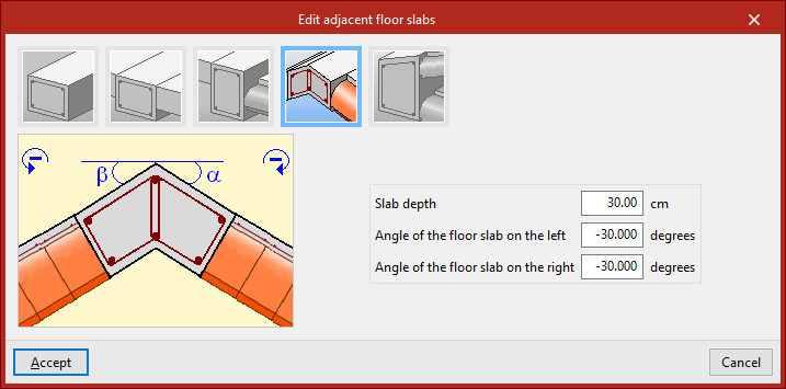
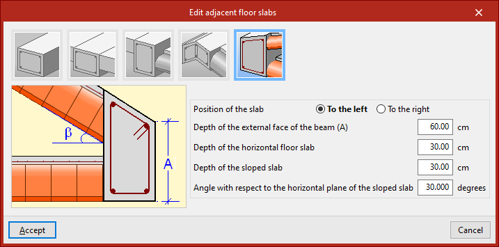
Edit adjacent floor slabs
This option allows you to edit the floor slabs adjacent to the beams. This way, you can define the depth of flat beams, as well as specify the slabs shown in the beam detailing drawing. It is also considered in the fire resistance check for steel beams.
Beams are selected with the left mouse button or by drawing a selection area, then confirmed with the right mouse button.
In the window that appears, there are several options:
- First, an "Unconnected beam" can be defined.
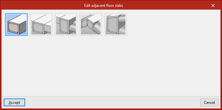
- If "Level slabs" is selected, you can input the "Slab depth to the left" and "to the right", as well as define the "Type", either "Generic" or "One-way", including the "Height" and the "Width of the reduced hollow block".
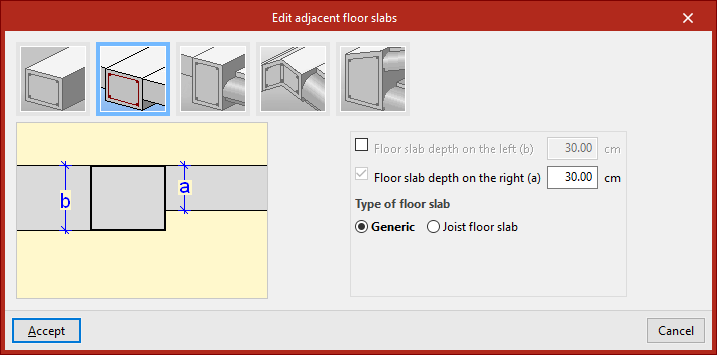
- In the case of "Slabs with step", in addition to the "Depth", the "Step height" and its "Position", "To the left" or "To the right", are indicated.
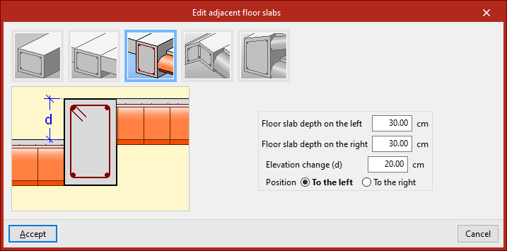
- You can also define a "Meeting of inclined slabs" by inputting the "Slab depth", the "Inclination angle to the left" and "to the right".
- For an "Eaves meeting of sloped roof", in addition to the "Position of the slab", define the "Depth of the external face of the beam", the "Depth of the horizontal floor slab", the "Depth of the sloped slab", and the "Angle with respect to the horizontal plane of the sloped slab".
Once the adjacent slabs are defined, click "Accept".
Edit beam references
To edit the reference of a beam, select this option and then click on the beam. Once activated, type in the desired "Reference" and then click "Accept".
Edit continuous beam references
This option allows you to edit the references of continuous beams. Similarly, click on the continuous beam, activate and type in the desired "Reference", and then click "Accept".
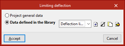
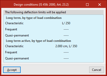
Beam deflection limit
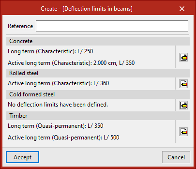
This option allows you to specify whether the deflection limit for the selected beam is defined according to the "General project data" or from "Data defined in the library", which can be configured specifically.
In the latter case, a set of "Deflection limits in beams" must be created with the available options for the different materials shown ("Concrete", "Rolled steel", "Cold-formed steel", and "Timber").
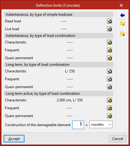
The following deflection limits can be specified:
- Instantaneous, by type of simple load case (Dead load, Live load)
- Instantaneous, by type of load combination (Characteristic, Frequent, Quasi-permanent)
- Long term, by type of load combination (Characteristic, Frequent, Quasi-permanent) (for "Concrete")
- Long term active, by type of load combination (Characteristic, Frequent, Quasi-permanent)
The assistant on the right allows you to import the design conditions from the concrete standard selected in the "General data" tab under "Project".
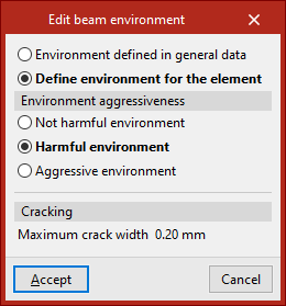
Edit beam environment
This option allows you to specify whether the "Environment defined in general data" is used for the selected beam or if you want to configure it specifically by choosing "Define environment for the element".
In the second case, depending on the selected code, it may be necessary to define the "Environment aggressiveness" or the "Environment class" and the "Designation" from the available ones, which will determine or allow input of the "Maximum crack width", as indicated in the "Cracking" section.
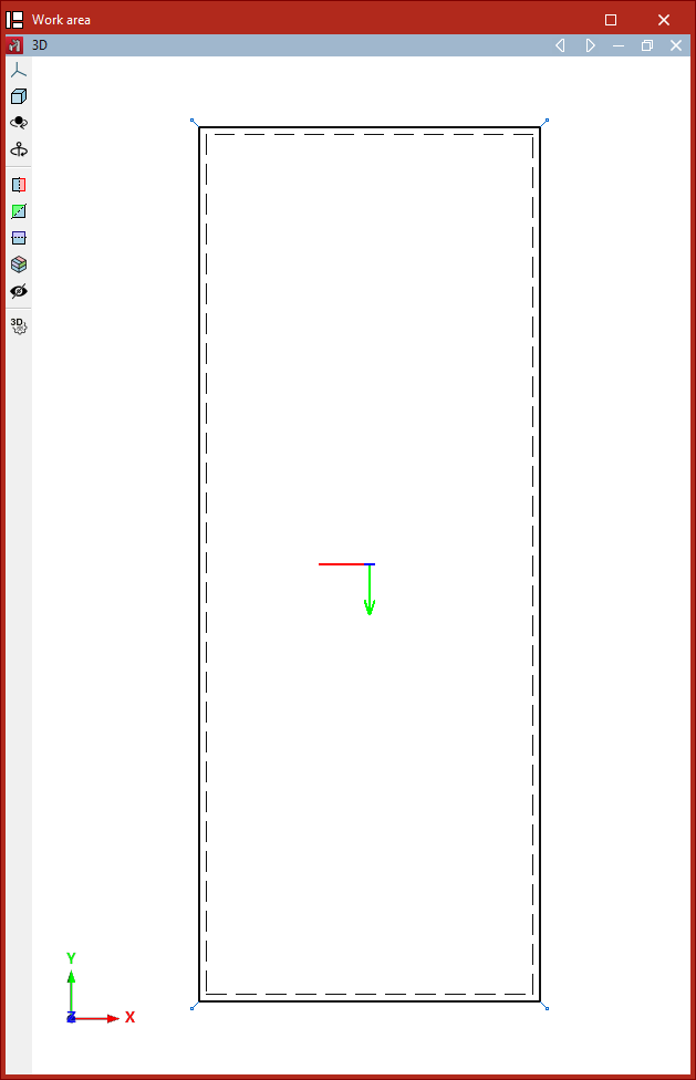
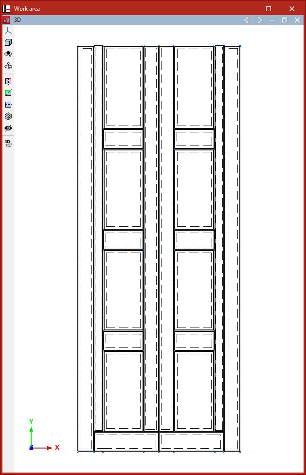
Entering shells
Shells are entered using the following option, available in the "Shells" group of the top toolbar, under the "Geometry" tab (in the "Structure" section).

New
The "New" option allows you to insert a new shell into the model.
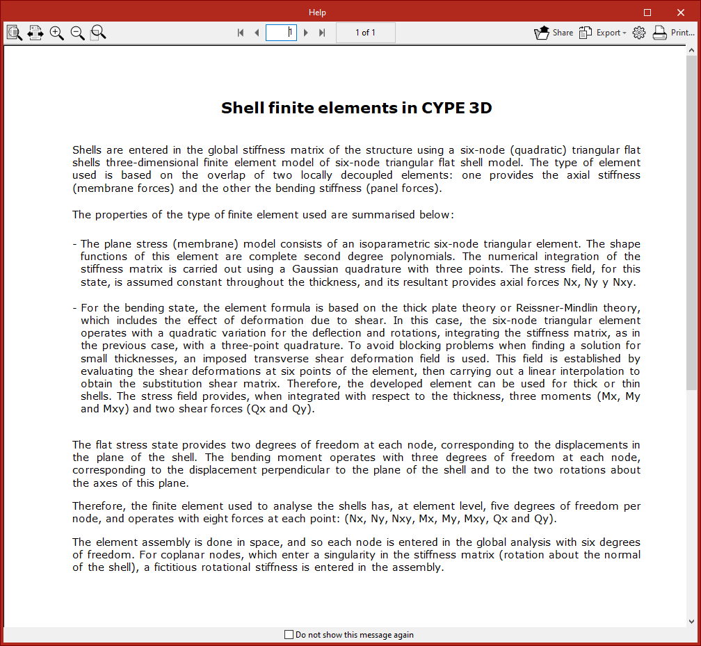
When you click this option, a message first appears explaining how the program treats finite element shells and their characteristics. You can check "Do not show this message again" if desired.
Then, the "New" window opens, allowing you to define the shell's characteristics.
Defining the shell section and material
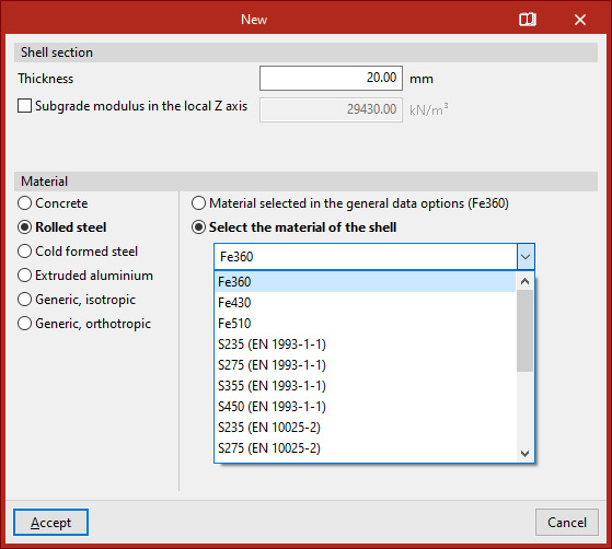
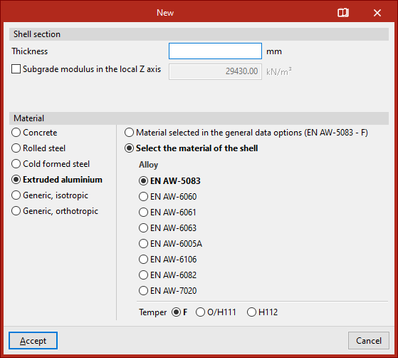
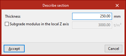
At the top of the "New" window, the "Shell Section" data is shown, including its "Thickness" in the selected measurement units.
You can activate and enter a "Subgrade modulus in the local Z axis". This setting lets the program consider the elastic support of the shell along the axis perpendicular to its plane. This is useful for simulating scenarios like shells resting on soil.
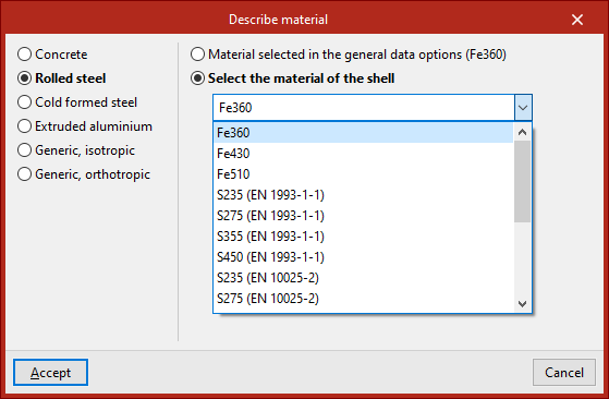
Next, the "Material" of the shell is defined. Available options include:
- Concrete
- Rolled steel
- Cold-formed steel
- Extruded aluminum
- Generic, isotropic
- Generic, orthotropic
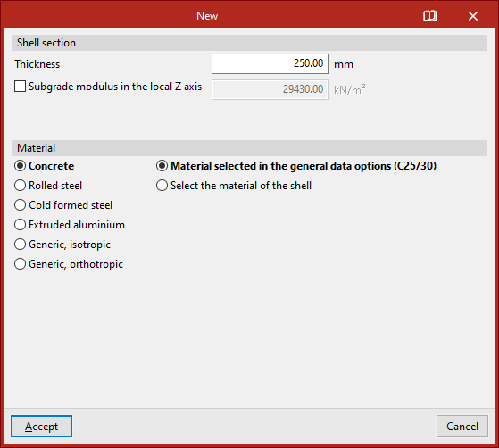
If one of the first materials is chosen, an option appears on the right to either "Material selected in the general data options" or "Select the material of the shell" directly from a dropdown list.
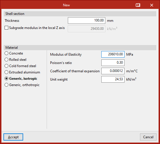
Generic isotropic material shells
If "Generic, isotropic" is selected, you must directly specify the "Modulus of Elasticity", "Poisson’s ratio", "Coefficient of thermal expansion" and the "Unit weight".
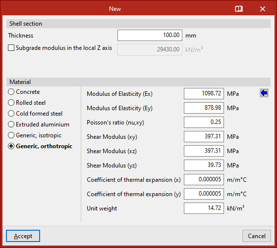
Generic orthotropic material shells
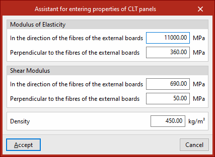
If "Generic, orthotropic" is selected, you must specify the "Elastic modulus" in both X and Y directions (Ex, Ey), "Poisson’s ratio (nu, xy)", the "Shear modulus" in the XY, XZ, and YZ planes, the "Thermal expansion coefficient" in X and Y and the "Unit weight".
This option is useful for analysing structures made of cross-laminated timber (CLT) panels.
To assist the user, a button on the right provides access to a "Assistant for entering properties of CLT panels".
This tool helps input data as specified by a CLT panel manufacturer in their European Technical Assessment (ETA) document.
Inserting the shell into the model
After clicking "Accept" in the "New" window, you define the polyline points that outline the shell in the work area using the left mouse button.
As with inserting bars, you can use object snaps and template snaps, among other options.
During the input process, you can "Erase the last entered point", or "Erase all entered points", using the controls provided in the dedicated input box.
Once all perimeter points are selected, right-click to finish.
After inserting the first shell, you can continue drawing more shells in the model, or right-click to return to the definition panel. When clicking "Cancel" or closing the panel, you exit the option.
The shell will be connected to the rest of the structure if its edges are in contact with its edges, or if there are nodes or bars within its geometry.
Editing shells ("Geometry" tab)
The options to delete, move, join, split, and edit the geometry, section, and material of shells are found in the "Shells" group of the top toolbar, within the "Geometry" tab (under the "Structure" section).

These options are only activated if shells have already been entered in the model.
Delete
The "Delete" option allows you to delete a group of shells.
To do so, select the shells you wish to delete using the left mouse button or a selection window, then right-click.
Section
The "Describe section" option allows you to edit the geometry of a group of shells.
Select the shells with the left mouse button or by drawing a selection window, then right-click.
In the pop-up window, you can modify the "Thickness" of the shell using the selected units and specify the "Subgrade modulus in the local Z axis", if desired.
Click "Accept" to apply the changes.
Material
The "Material" option allows you to edit the material of a group of shells.
Select the shells with the left mouse button and right-click to confirm. In the window that appears, choose the material you wish to assign.
Then click "Accept".
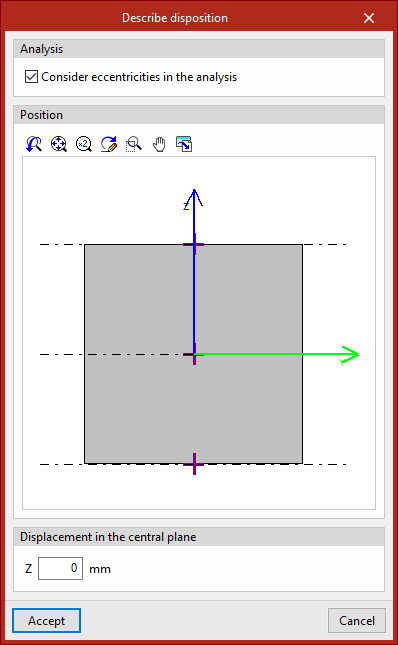
Disposition
Using the "Disposition" option, you can adjust the location of shells relative to their reference plane.
Select the shells with the left mouse button, then right-click.
In the "Position" section of the pop-up window, click on one of the crosses in the viewer to position the shell in relation to its reference plane.
At the bottom, you can add a "Displacement from the central plane" by entering its value.
Move
The "Move" option lets you move the nodes along the perimeter of a shell to a new position.
After selecting the option, first select the shell to move using the left mouse button. Then, select the nodes of the shell you want to move using the left mouse button again. Confirm the selection by right-clicking.
Now, use the left mouse button to define two points that determine the direction and distance of the movement.
Join
The "Join" option allows you to merge multiple shells that share a common edge and lie on the same plane. Select the shells with the left mouse button or by drawing a selection area, then right-click.
If grouped planes have been defined, the program will also join the corresponding shells in those planes.
Divide
The "Divide" option lets you divide shells. After selecting the option, use the left mouse button to select two points that define the cutting segment. The shells will be completely divided, even if the segment only partially intersects them.
If grouped planes have been defined, the program will also divide the corresponding shells in those planes.
Invert z-axis
To reverse the direction of the local Z-axis of shells, select the "Invert z-axis" option and then a group of shells using the left mouse button.
Clicking the right button will reverse the direction of the local Z axis of the selected sheets.
Define x-axis
The "Define x-axis" option lets you change the direction of the local X-axis of a shell.
To do this, with the left mouse button, select the edge of the shell that you want to use to define the local X-axis direction, then right-click to confirm.
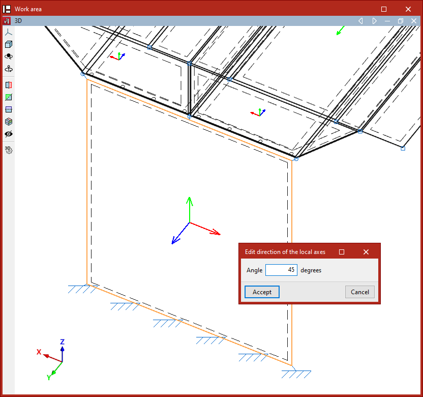
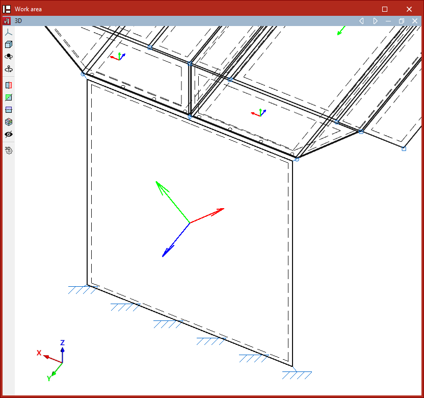
Local axes
The "Local axes" option allows you to edit the direction of the local axes of a group of shells.
After selecting the shells and right-clicking, a window will open where you can enter the "Angle" between the local axes and the orientation defined by the edge that sets the X-axis direction.
Geometry generation tools: planes, nodes and bars, and tetrahedral meshes
To automatically generate planes, nodes, bars and tetrahedral meshes in CYPE 3D, use the options in the "Generate" menu, which can be found in the "Tools" panel at the top of the interface, within the "Geometry" tab (under the "Structure" tab).

The options available in this menu are as follows:
- Plans
- Nodes and bars
- Tetrahedral meshes
Each of these features is described below.
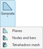
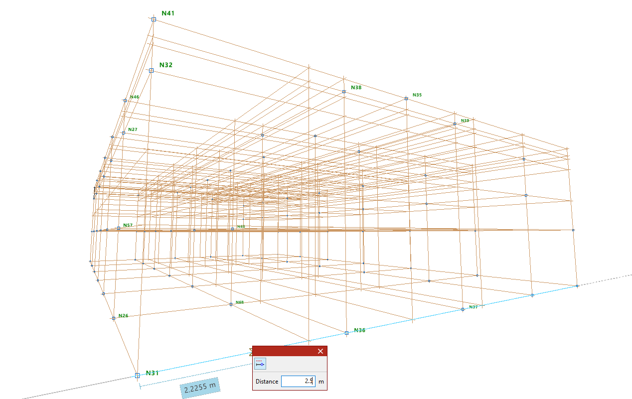
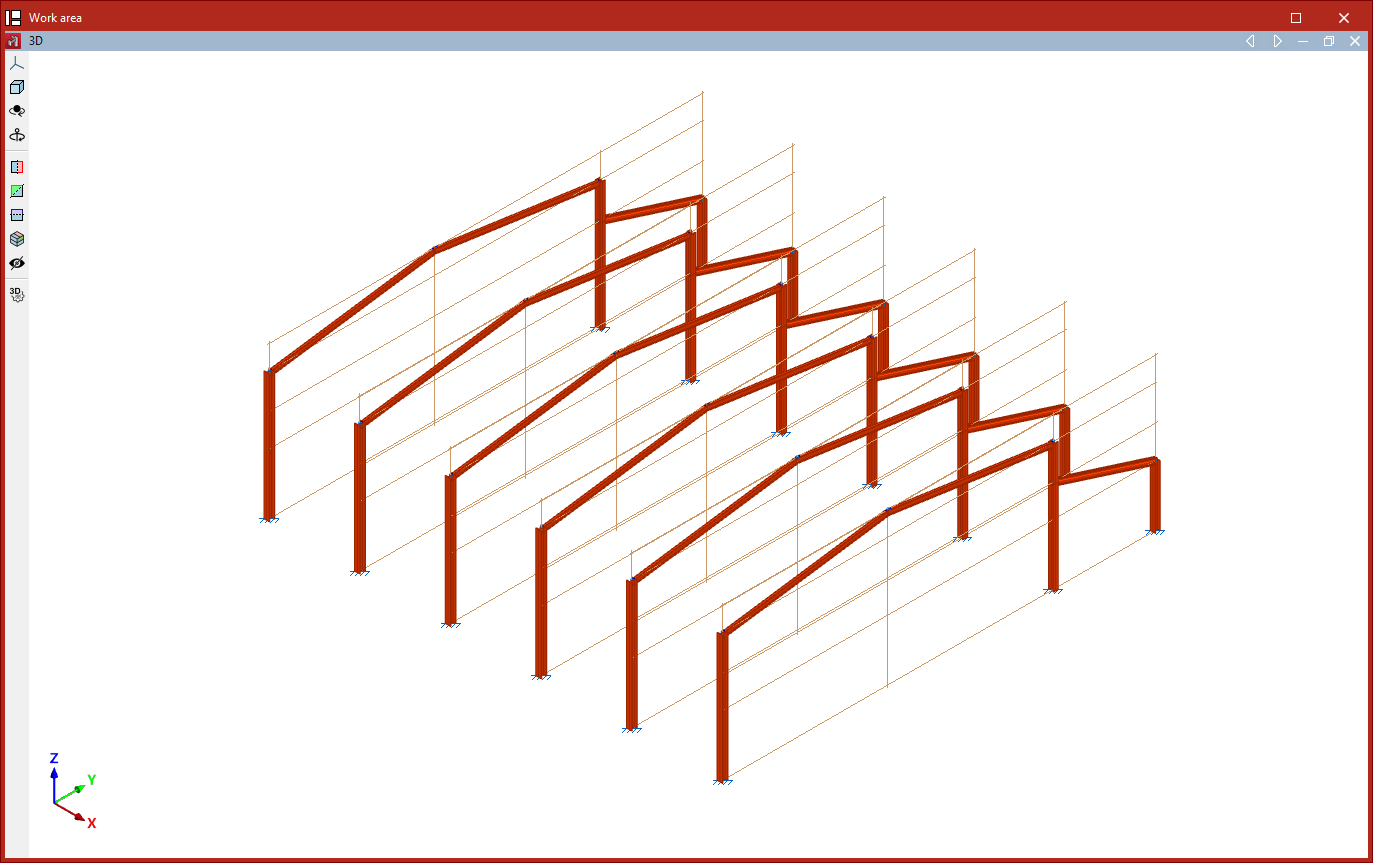
Generating planes
The first option in the "Generate" menu, "Planes", allows you to generate planes parallel to a selected plane.
To do this, in a 3D view, left-click to select two reference lines contained within the plane you wish to copy.
Only planes perpendicular to a global reference axis can be generated.
Next, in the "Plane generation" window, enter the "Number of planes to generate" and the "Separation between planes", and decide whether you want to "Group generated planes".
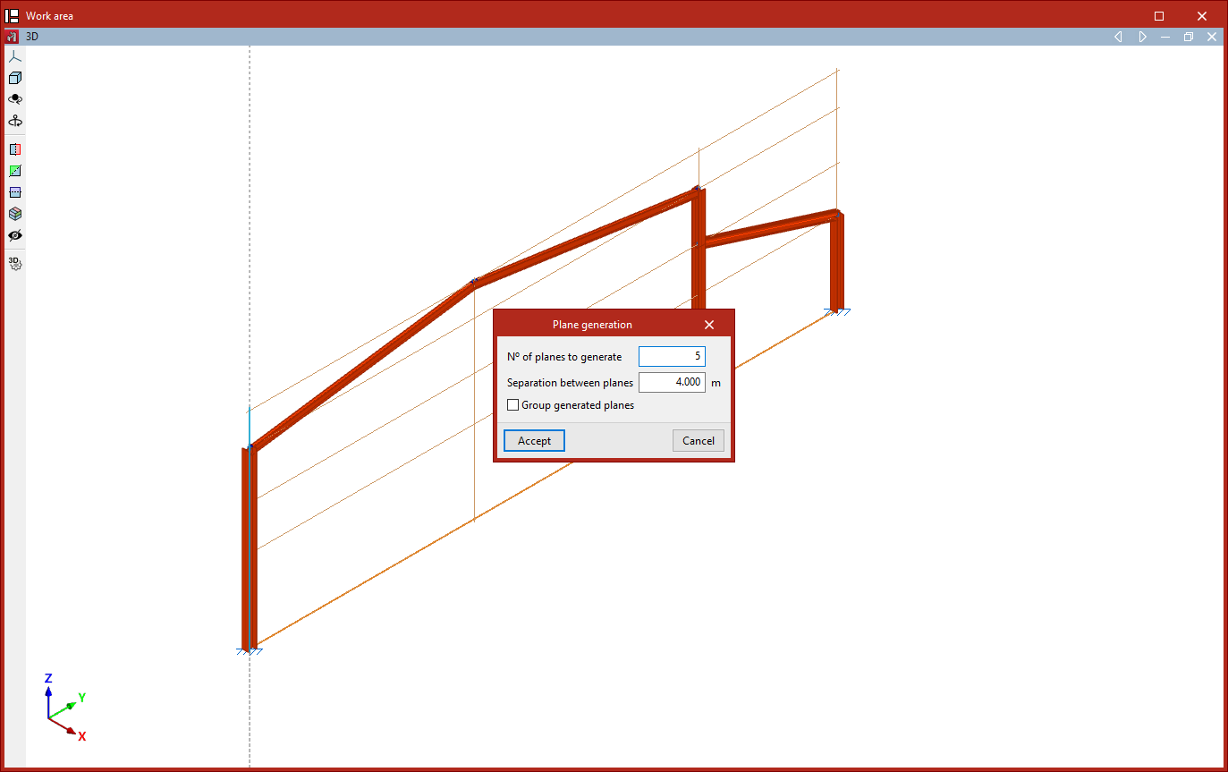
After clicking "Accept", the program generates the specified planes and copies the data entered into the original drawing, including nodes, bars, shells and loads.
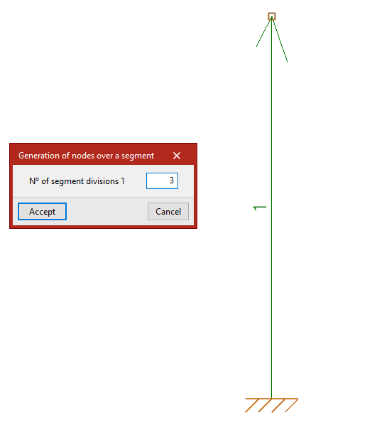
Generating nodes and bars
The next option in the "Generate" menu, "Nodes and bars", allows you to generate nodes and bars by specifying the generation segments and the number of divisions per segment.
This generation can be linear if only one segment is selected, planar if two are selected, or spatial if three are selected.
Generating nodes on a segment
To generate a linear series of nodes along a segment, first left-click on the start node and the end node of the segment you wish to divide into equal parts.
Next, right-click. The "Generate nodes on a segment" window will open, where you should enter the "Number of segment divisions".
After clicking "Accept", vertices are created at the segment's division points.
Generating a two-dimensional node mesh
To create a flat or two-dimensional drawing, after selecting the "Nodes and bars" option again, left-click on the start node and the end node of the first segment.
Next, to select the second segment, left-click on its end point. The segments do not need to be perpendicular to one another.
The program will number the segments as they are selected.
Right-clicking opens the "Generate a two-dimensional node mesh" window, which contains the following options:
- If desired, you can "Generate nodes only" by ticking the first box. This way, no beams are generated.
- The "Number of segment divisions" is shown below.
- It is also possible to "Group parallel bars" for each segment. This option automatically groups the bars generated parallel to the main segment, in exactly the same way as the "Group" option in the "Bar" menu.
- With the "Create an element between aligned bars" option, the bars forming the divisions within each segment will form a single part, in the same way as the "Part" option in the "Bars" group would.
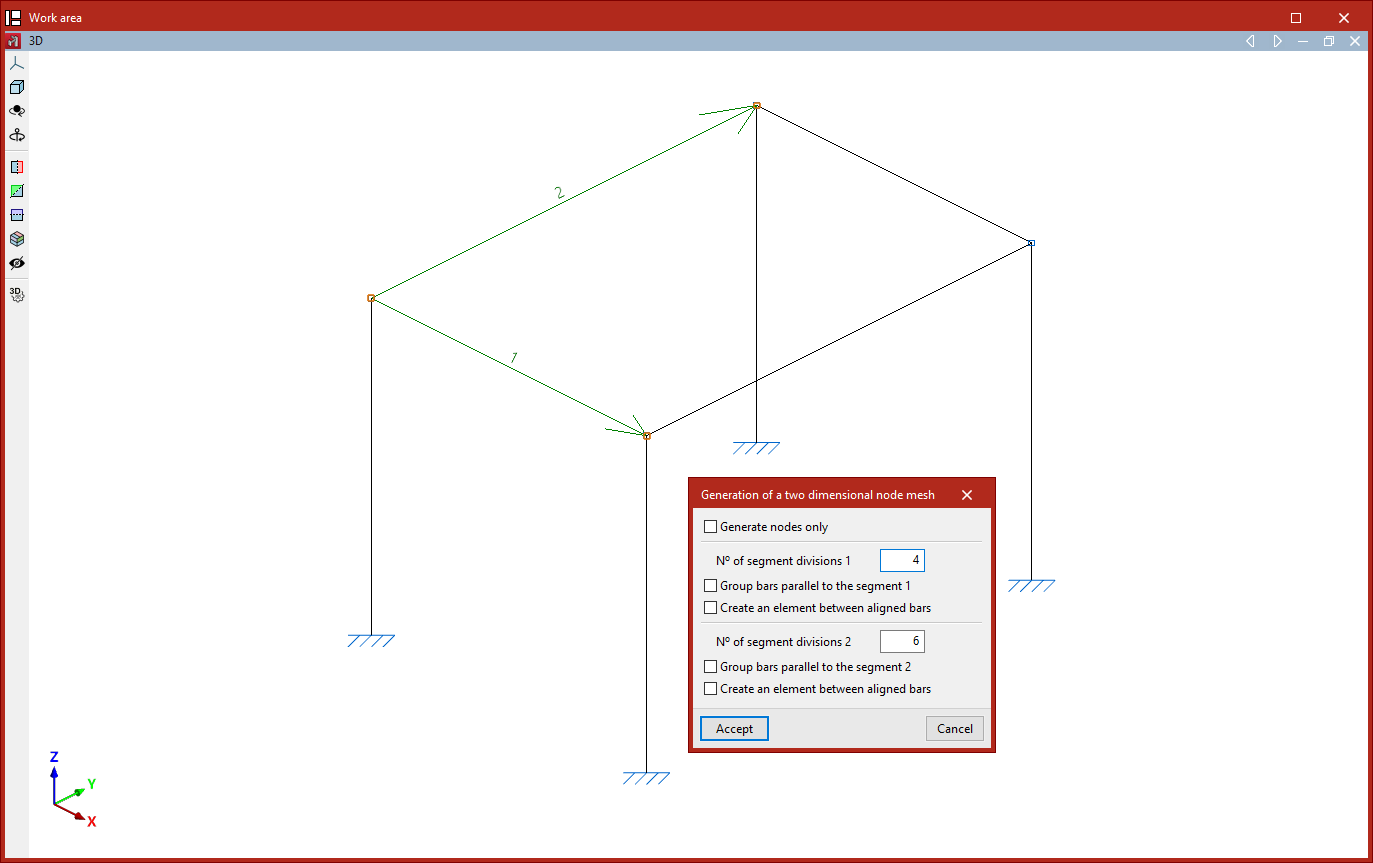
After clicking "Accept", a mesh of nodes is generated at the points where the segments meet. If specified, beams are also generated to connect these nodes.
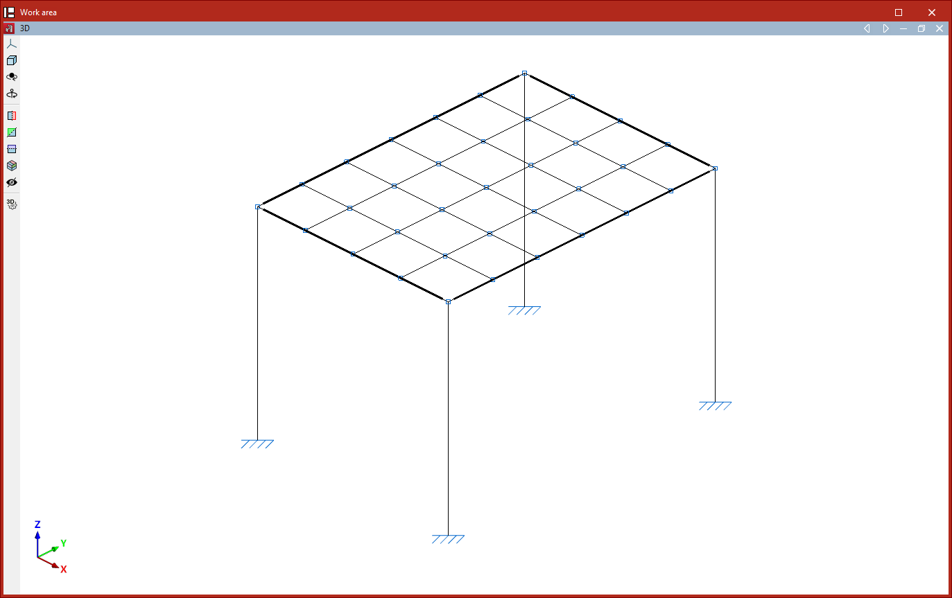
Generating a three-dimensional mesh
Finally, the generation can be spatial. In this case, after selecting the "Nodes and bars" option, you must select three segments using the left mouse button.
First, left-click to select the start and end points of the first segment. Next, to select the second and third segments, simply left-click on their end points.
After right-clicking, the "Generation of a three dimensional node mesh" window appears. The options are identical to those described for generating 2D meshes. In this case, the divisions of the three segments are specified.
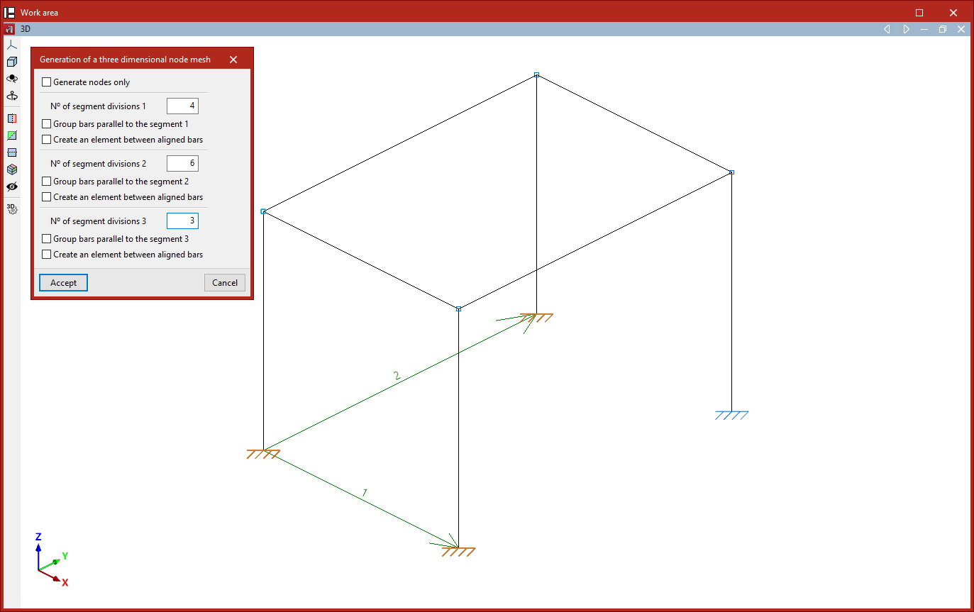
Clicking "Accept" results in a spatial mesh of nodes and bars connecting the division points of the specified segments.
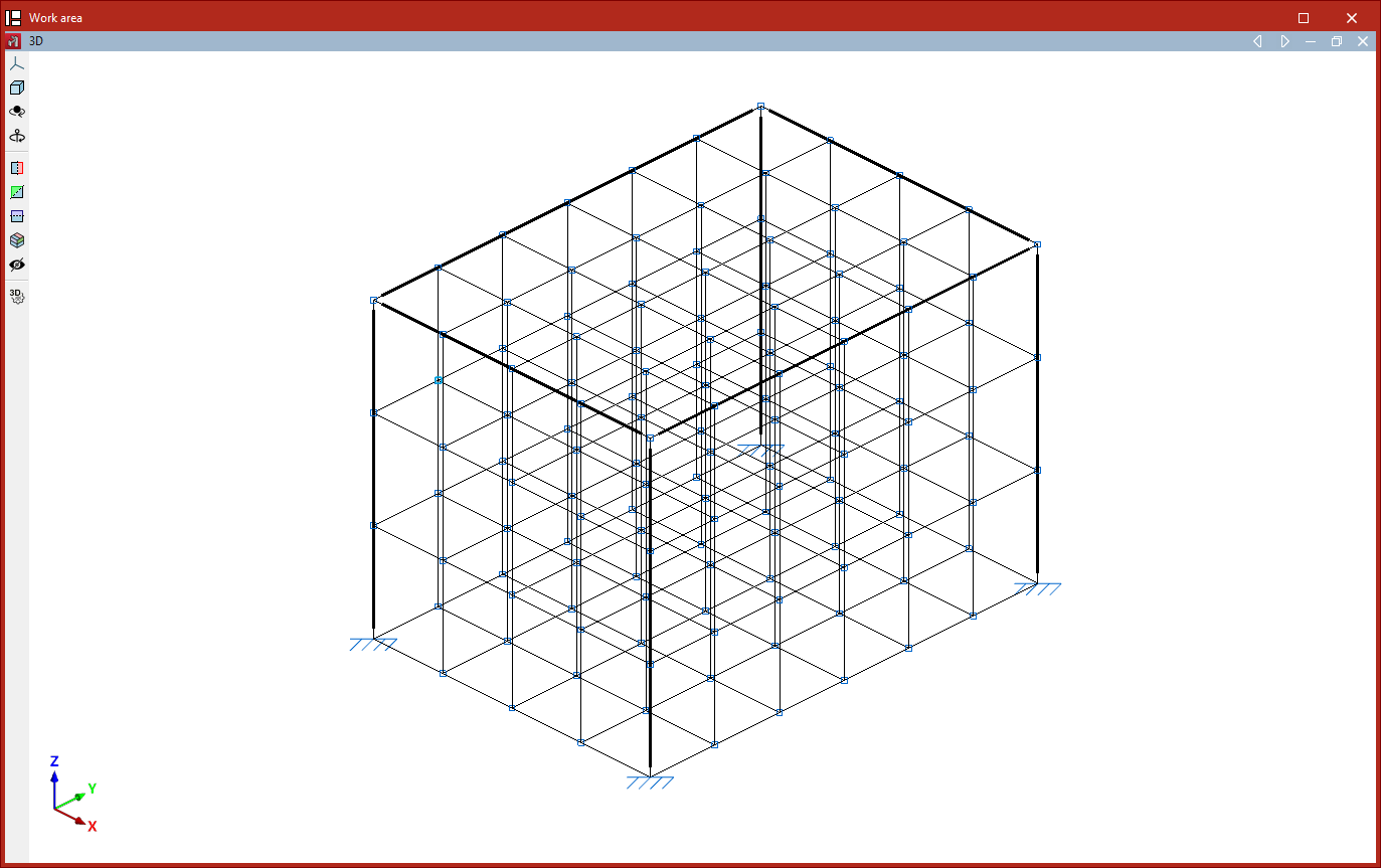
Generation of tetrahedral meshes
The "Tetrahedron mesh" option in the "Generate" menu allows you to generate a spatial tetrahedral mesh.
To do this, define two segments that form one of the mesh planes. Both segments share the same starting point. Click the left mouse button to select the start and end points of the first segment, and then the end point of the second segment.
This opens the "Generate a tetrahedron mesh" window, which contains the following options:
- Firstly, the "Number of divisions" is specified for each of the two segments, along with the "Distance between planes", which corresponds to the edge length of the generated tetrahedral mesh.
- There are then a number of options available for grouping the generated bars:
- Turning on "Group bars in the bottom plane" groups the bars contained within the plane formed by the two selected segments.
- The second checkbox, "Group bars on the top plane", allows you to group the bars contained in the plane parallel to the previous one.
- The last option allows you to "Group bars in between planes", i.e. the diagonal edges that make up the tetrahedral mesh.
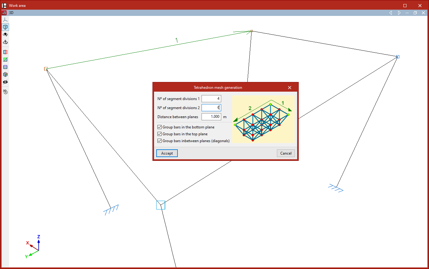
After clicking "Accept", the program generates the tetrahedral mesh of nodes and bars.
The order in which the segments are selected determines the orientation of the tetrahedral mesh edge (upwards or downwards relative to the plane formed by the two segments).
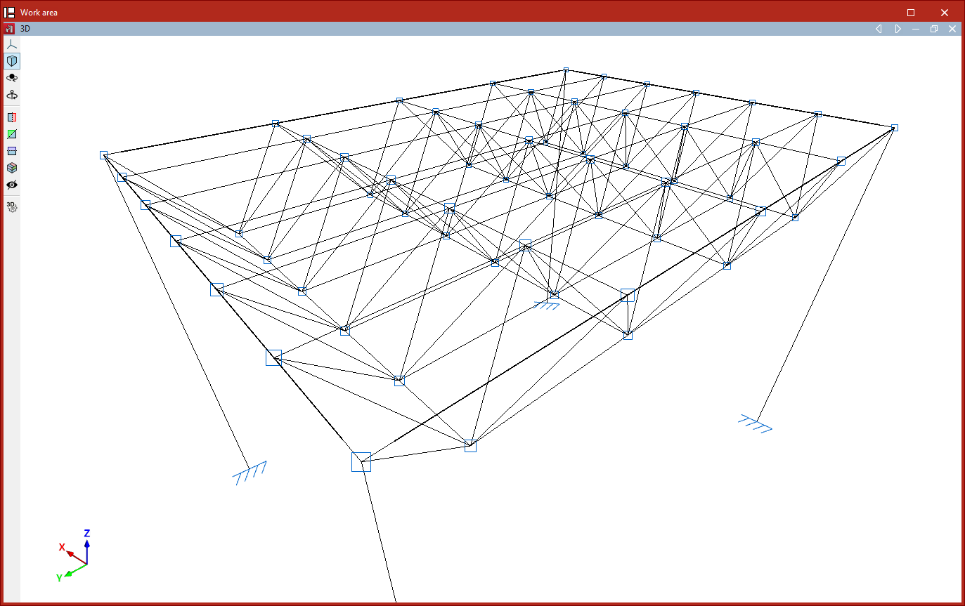
Geometry editing tools
The tools for editing the geometry of model elements in CYPE 3D are located in the “Tools” panel at the top of the interface, within the “Geometry” tab (under the “Structure” tab).

They are as follows:
- Move items
- Copy items
- Rotate elements in the xy plane
- Rotate elements about an axis defined by two points
- Rotate elements in the xy plane given three points
- Element symmetry in the xy plane
- Element symmetry with respect to a plane
- Search
- Assign reference
Move elements
The "Move elements" option allows you to move a selection of elements to a new position in the workspace:
- After clicking on the option, select the elements to be moved one by one using the left mouse button, or highlight a selection area.
- Then, click the right button to confirm your selection.
- Next, use the left mouse button to click on two points that define the start and end of the movement.
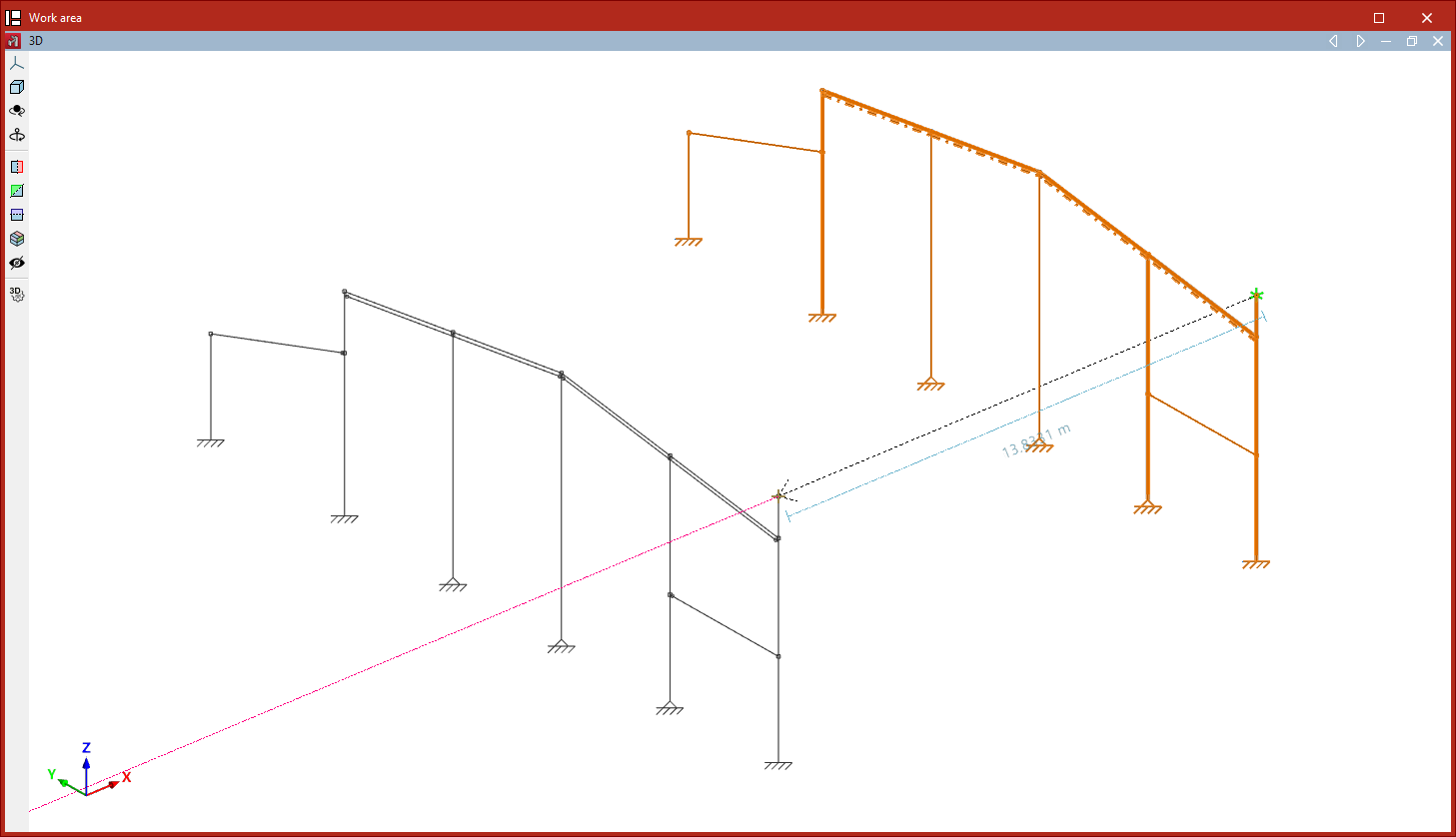
Copy elements
The "Copy elements" option allows you to copy a selection of elements to a new location:
- After clicking on the option, select the items to be copied one by one using the left mouse button, or highlight a selection area.
- Then, click the right button to confirm your selection.
- Next, left-click to select two points that define the start and end points of the copied elements’ movement.
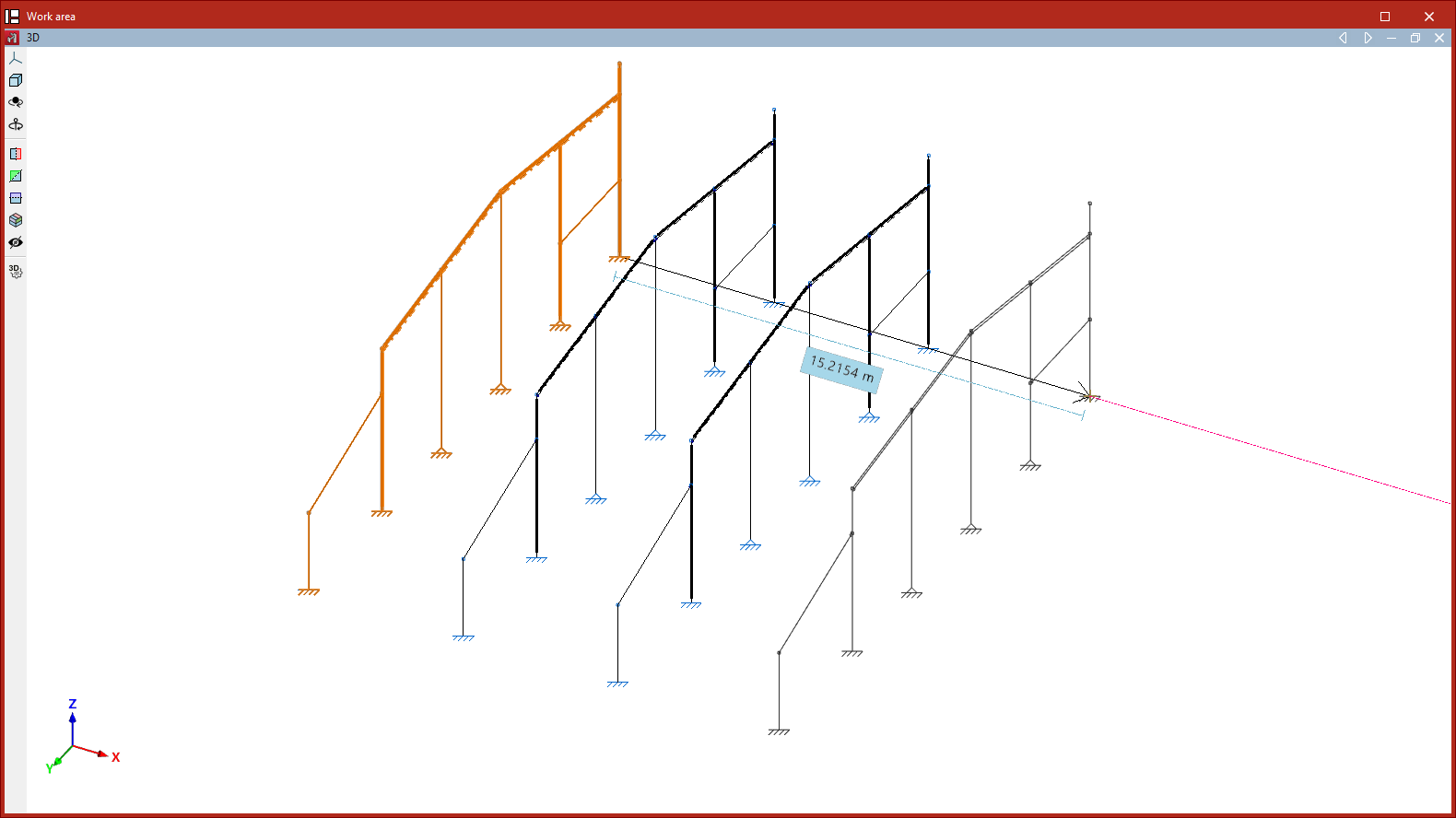
Rotate elements in the xy plane
The "Rotate elements in the xy plane" option allows you to rotate a selection of elements around the global Z-axis:
- After clicking on the option, use the left mouse button to select the items you wish to rotate.
- Click the right mouse button to confirm your selection.
- Next, left-click on the rotation point.
- Next, using the left mouse button again, select two points that define the sides of the rotation angle.
- Finally, the "Rotation angle" value displayed by the program must be confirmed by clicking on the green tick.
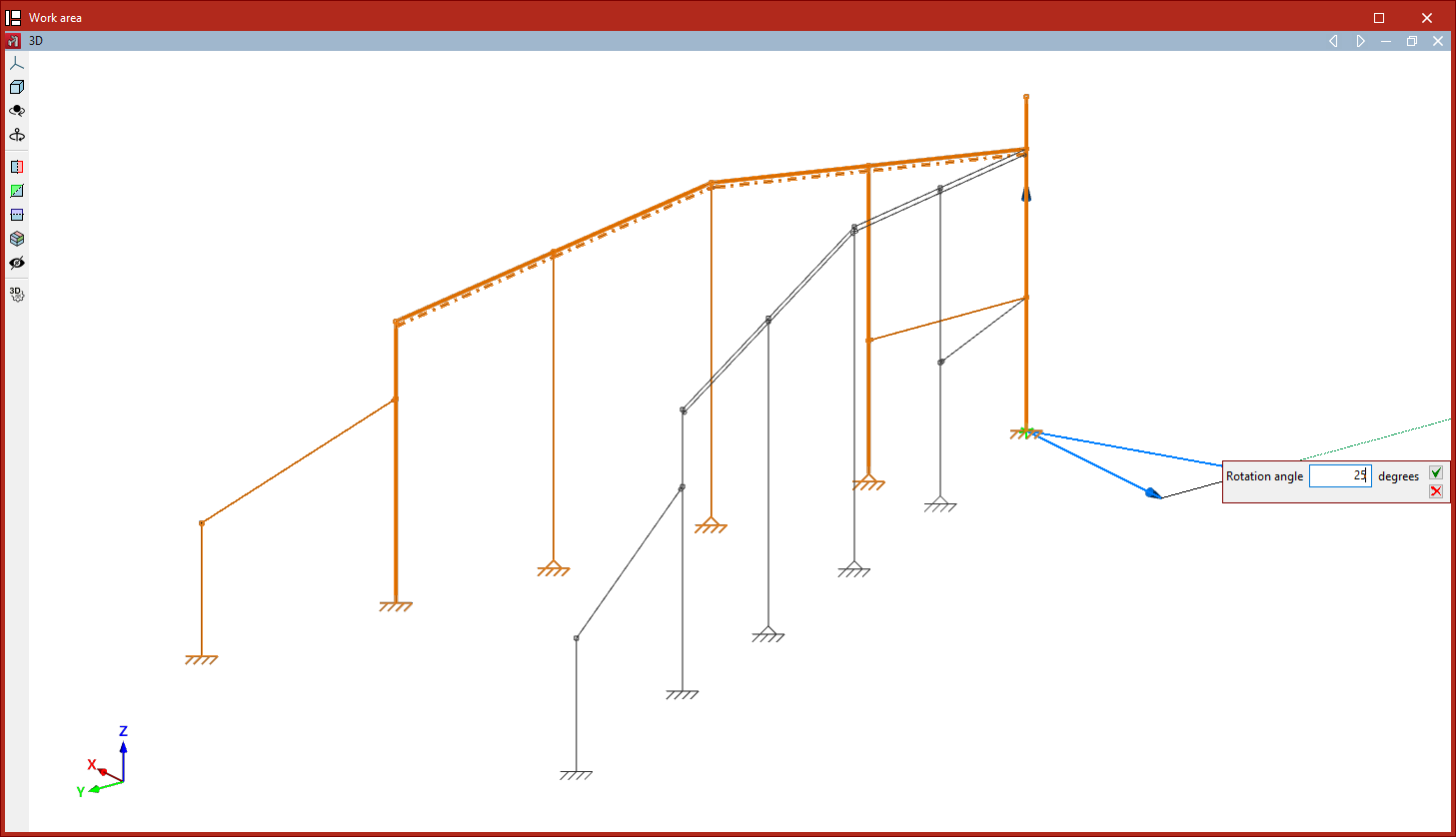
Rotate elements about an axis defined by two points
The "Rotate elements about an axis defined by two points" option allows you to rotate a selection of elements around any axis defined by the user:
- After clicking on the option, select the items to be rotated using the left mouse button.
- Click the right mouse button to confirm your selection.
- Now, use the left mouse button to select the two points that define the axis of rotation.
- Finally, enter the "Rotation angle" around the specified axis and click on the green tick to confirm the operation.
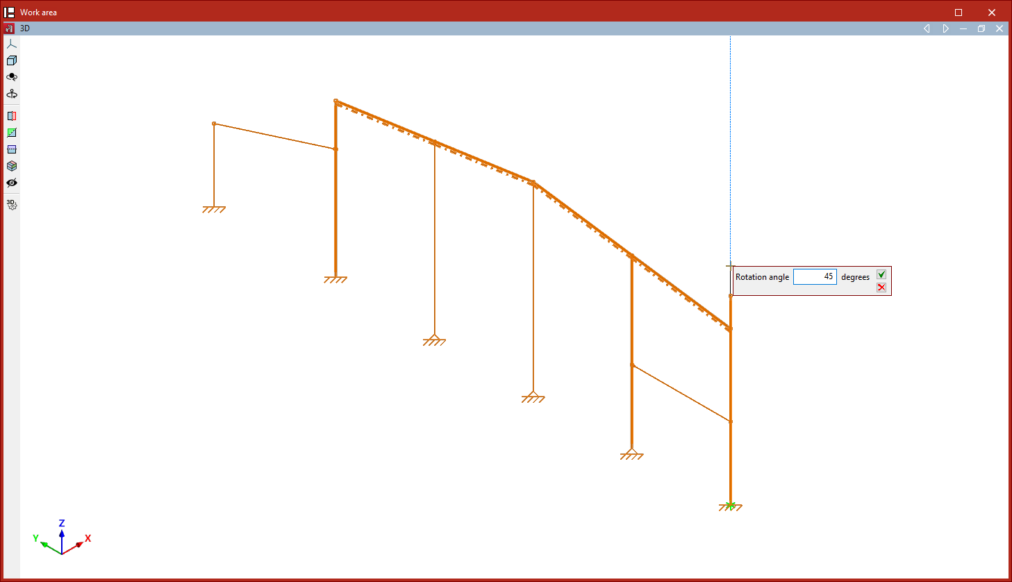
| Note: |
|---|
| If any of the rotation operations mentioned above are performed in a 2D view, the rotation takes place in the plan view. To do this, select the elements using the left mouse button and confirm the selection with the right mouse button. Then, simply click the left mouse button to select two points that define the angle of rotation. |
Rotate elements in the xy plane given three points
The "Rotate elements in the xy plane given three points" command is used to rotate a selection of elements around the global Z-axis, relative to the origin specified by the user and by an angle defined by any three points:
- After clicking on the option, select the items to be rotated using the left mouse button.
- Click the right button to confirm your selection.
- Next, left-click to select the rotation point.
- Next, click on any three points with the left mouse button to define the magnitude of the rotation, thereby defining the vertex and the two sides of the axis of rotation.
- Finally, confirm the "Rotation angle" by clicking on the green tick.
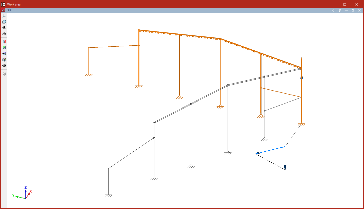
Element symmetry in the xy plane
The "Element symmetry in the xy plane" option allows you to create a mirror image of a selection of elements with respect to the plane defined by a user-defined vector and the global Z-axis:
- After clicking on the option, use the left mouse button to select the elements you wish to copy symmetrically.
- Click the right mouse button to confirm your selection.
- Next, use the left mouse button to select the two points that define the centre of symmetry and the direction of the vector in the global XY plane.
If the operation is performed in a 2D view, the symmetry is applied with respect to the line defined by the vector:
- To do this, select the items using the left mouse button and then right-click.
- Next, click the left mouse button to select two points that form the axis of symmetry.
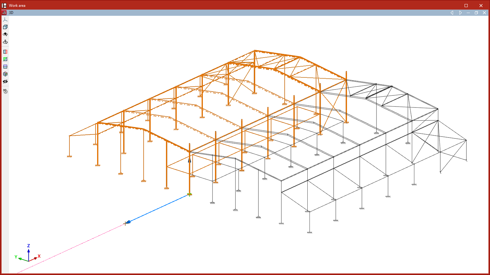
Element symmetry with respect to a plane
The "Element symmetry with respect to a plane" option allows you to create a mirror image of a selection of elements about a plane defined by three points:
- After clicking on the option, use the left mouse button to select the elements to be mirrored.
- Click the right button to confirm your selection.
- Next, left-click on the three points that define the symmetry plane.
As in the previous case, if this operation is performed in a 2D view, the symmetry is applied about a line defined by two points.
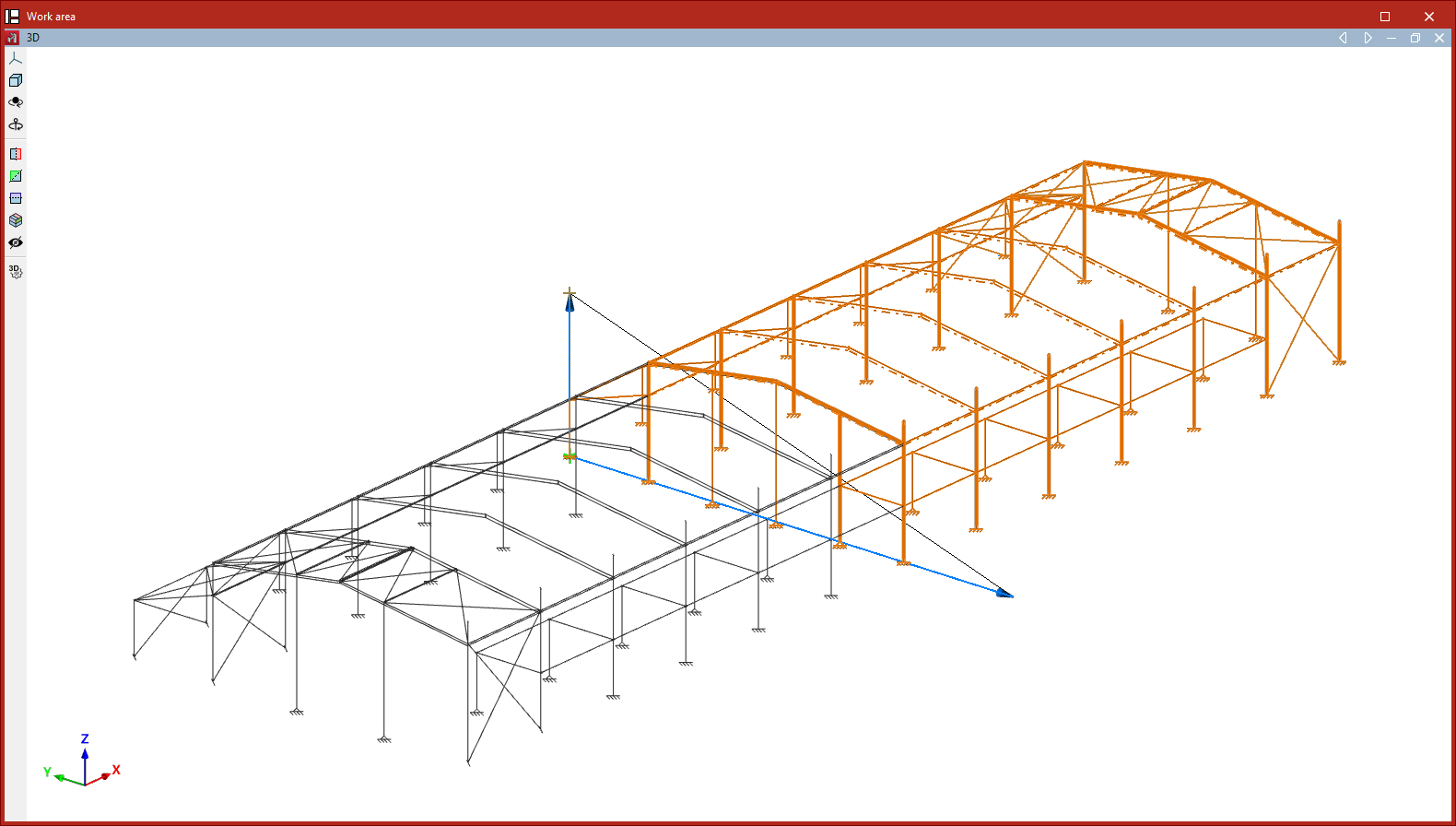
Search
The "Search" option allows you to search for elements of the selected "Element type" ("Nodes", "Bars", "Parts", "Deflection groups" or"Connections") by entering their "Reference".
If you wish to search for items by entering the full text of the reference, tick the "Only whole word" box. If you untick it, you can search by entering just part of the text.
The program will highlight in red any elements whose reference matches the text entered and will frame them with magenta lines in the model view.
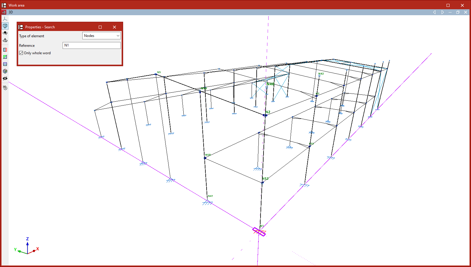
Assign reference
The program automatically generates element references based on the options selected in the "Numbering" section of the "Project" tab. To edit element references at a later stage and assign them the references of your choice, use the "Assign reference" option in the "Tools" section of the "Geometry" tab.
When you click on this option, you must first select the "Element type" from the drop-down menu (whether "Nodes", "Bars", "Parts", "Arrow groups" or "Beams") and specify whether the assignment will be single or multiple:
- Single
Allows you to assign the reference to a single element. To do this, after selecting the element, enter the desired "Reference" in the pop-up dialogue box. - Multiple
Allows you to assign a reference number to a selection of elements. To do this, after selecting the elements, enter a "Starting reference". The program will assign a sequential reference number to each element in the selection, starting from the starting reference.
If repeated references are defined, a warning will appear when printing reports or drawings, as well as when "Show issues" is selected.
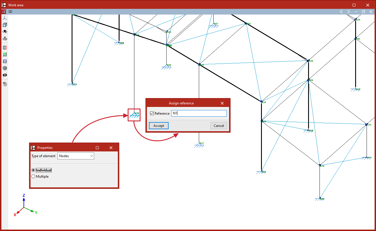
Model repair tools
The model geometry repair tool in CYPE 3D can be found in the "Tools" panel at the top of the interface, within the "Geometry" tab (under the "Structure" tab).

Check for nearby nodes
When importing, defining or editing the model, there may be instances where nodes are created too close together, at a distance of less than 1 millimetre.
Before performing the analysis (when using the "Analysis" option on the "Analysis" tab), the program checks that there are no nearby nodes. The program will report this situation with an error message and will also display the relevant issues.
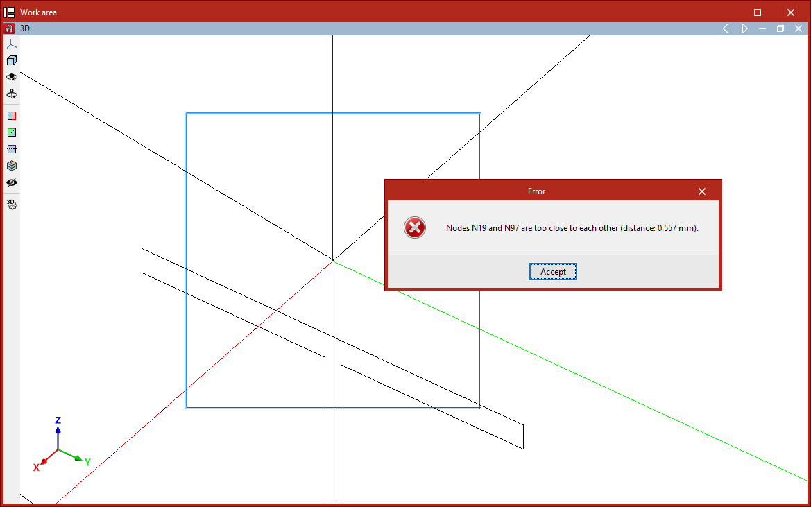
'Repair' option
The "Repair" option allows you to repair the model when there are nodes that are too close together. When you click on this option, the program will analyse the model’s geometry and attempt to correct it, if necessary.
Generating geometry by importing DXF or DWG files
In CYPE 3D, it is possible to automatically generate the structure’s geometry by importing data from a DXF or DWG file. To do this, use the “DXF or DWG” option, which is available in the “Import” section of the top toolbar, within the “Geometry” tab (under the “Structure” tab).

| Note: |
|---|
| This option allows for the automatic generation of beams, panels and/or sheets as native elements in CYPE 3D and differs from the template import function available via the "Edit templates" option, located in the toolbar at the top right of the interface. In the latter case, the elements of the imported .dxf or .dwg file are used solely as a reference or aid in the drawing process, via a snapping system. |
Select the DXF or DWG file
When you click on the "DXF or DWG" option, a dialogue box opens, allowing you to browse for a file in either of these two formats. The drawing units in the selected file must be set to metres.
Entity selection
Once you have selected and loaded the file, the "Entity selection" window appears.
The table on the left shows each "Layer" in the drawing and its "Colour". The viewer on the right allows you to view the elements contained in the file.
In the first column of the table, tick the relevant boxes to select the layers in the file that contain the elements you wish to import. When you do so, the elements assigned to each layer change colour in the viewer so that they can be easily identified.
You should check the "Import polygons as load panels" box if you wish to import the polygons contained in that layer as panels, and uncheck it if you wish to import them as sheets.
| Note: |
|---|
| You should only activate the layers containing lines that represent members, panels and/or sheets of the structure. These lines must have been entered accurately into the original program to ensure that the correct number of bars, panels and/or sheets is generated, with the correct dimensions and positioning. There is no need to import layers containing other types of information, such as text, details and symbols. |
Then click "Accept".
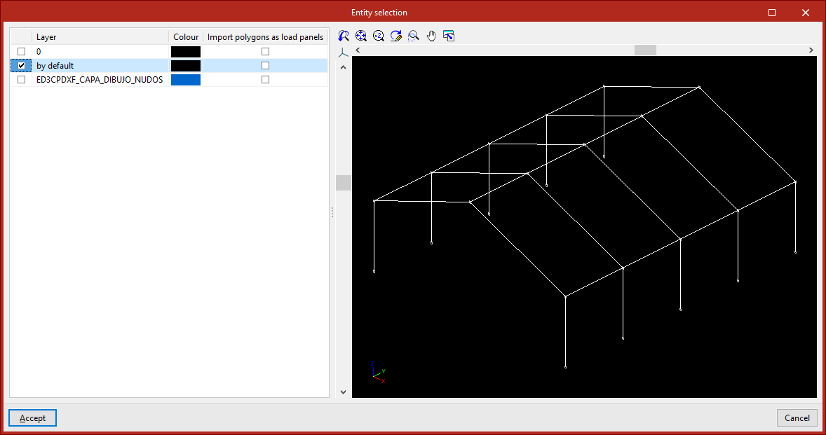
The program will read the lines in the drawing and convert them into beam-type elements, and will read and convert the polygons into slab-type elements, depending on the defined settings. If any elements cannot be imported, this will be indicated by a warning message.
During import, labels are created with the same name and colour as the existing layers in the .dxf or .dwg file. To manage these, use the "Labels" panel on the left-hand side. Imported elements are assigned to the same layer to which they were assigned in the .dxf or .dwg file.
Once the import is complete, you will need to define the sections of the elements and the external connections, and enter the loads and any other information required to complete the model.
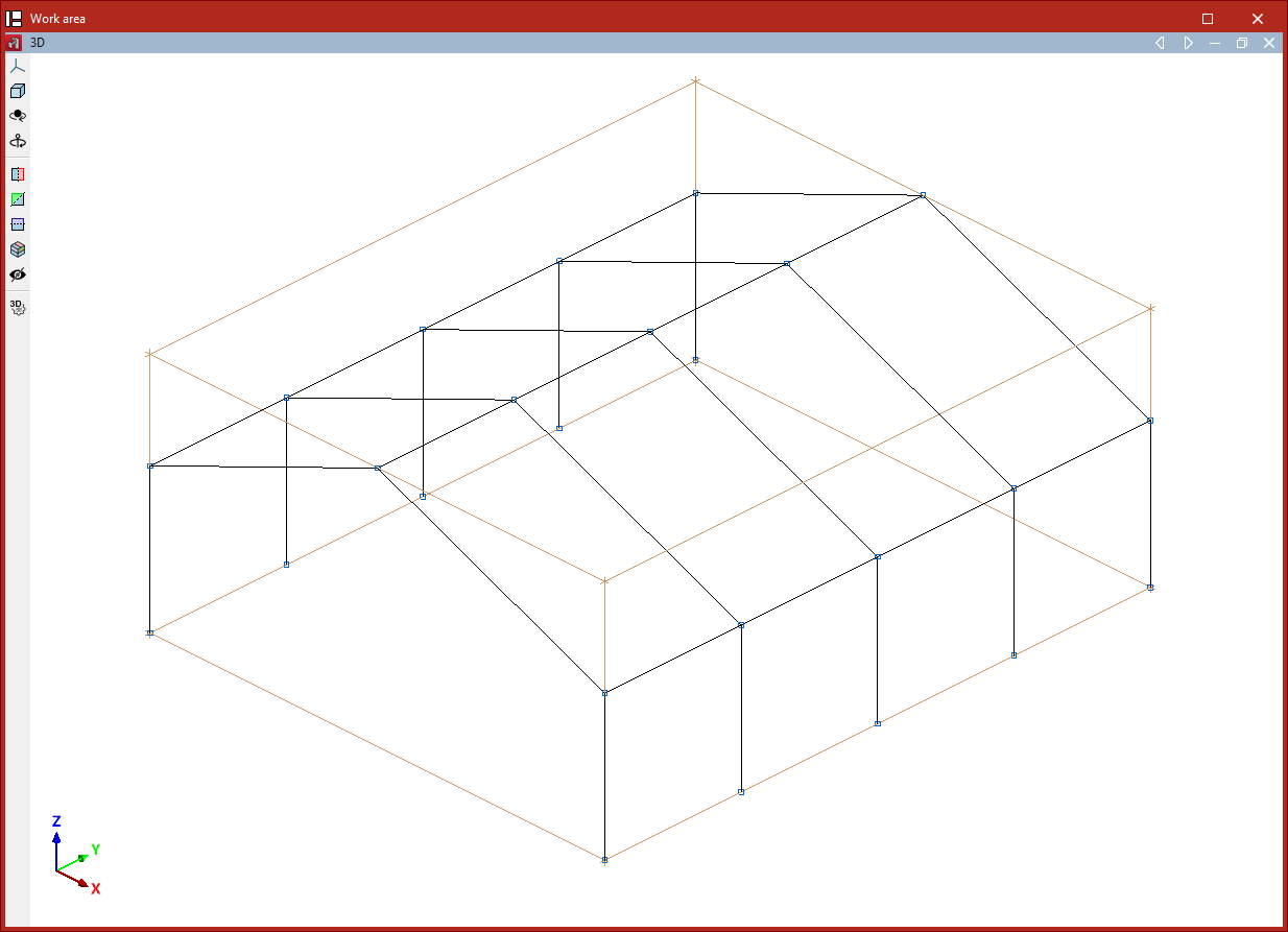
Layout of the elements imported into the model
If the project is empty at the time of import, the program will import the elements into the position specified in the file.
If the project contains any elements at the time of import, the program allows you to specify a reference point for inserting the geometry of the imported structure.
In this case, after clicking "Accept" in the "Entity selection" dialogue box, the program offers two options:
- The first option is "Import at the position defined in the DXF or DWG file".
- The second option allows you to "Select the reference point for the import". If you tick this option, after clicking "Accept" you can left-click to specify the position of the import reference point in space.

Generating geometry by importing text files
The geometry of the structure can be generated automatically in CYPE 3D from a text file. To do this, use the “Text file” option, available in the “Import” section of the top toolbar, within the “Geometry” tab (under the “Structure” tab).

Text file format
The program can import nodes, beams and shells from text files (with the .txt extension) in the following format:
- At the start of the text file, write the word NODES or JOINTS to define the nodes. On the next line, enter the node number, a space, the letter X, the = symbol, and the numerical value of the X-coordinate. Leave a space, then repeat the process for the node’s Y and Z coordinates. Each node is defined on a separate line.
- Next, the beams are defined by first typing the word BEAMS or FRAMES. Then, a beam is defined on each line by typing the beam number, a space, the starting node number, another space, and the ending node number.
- The shells are defined later, with the sequence titled using the word SHELLS. Similarly, each shell is defined on a separate line by entering the shell number, a space, and the node numbers that constitute the shell’s vertices, separated by spaces.
- Finally, the load panels are defined by typing the word PANELS. Each load panel is then defined on a separate line by typing the panel number, a space, and the node numbers that make up the panel, separated by spaces.
An example is shown on the right. You can download the corresponding .txt file via this link.
JOINTS
1 X=0 Y=0 Z=0
2 X=0 Y=0 Z=3
3 X=5 Y=0 Z=5
4 X=10 Y=0 Z=0
5 X=10 Y=0 Z=3
6 X=0 Y=3 Z=0
7 X=0 Y=3 Z=3
8 X=5 Y=3 Z=5
9 X=10 Y=3 Z=0
10 X=10 Y=3 Z=3
FRAMES
1 1 2
2 2 3
3 3 5
4 4 5
5 6 7
6 7 8
7 8 10
8 9 10
SHELLS
1 2 3 8 7
2 3 5 10 8
PANELS
1 2 3 8 7
2 3 5 10 8
Importing the text file
When you click on the option, the "Import geometry" window opens.
Here, if you have a file in the specified format, click the relevant button to the right of the "File name" field at the top to locate it on your hard drive.
The help text under the "Additional data" section specifies the format the text file must follow and also includes an example.
Once you have selected and opened the file, click "Accept".
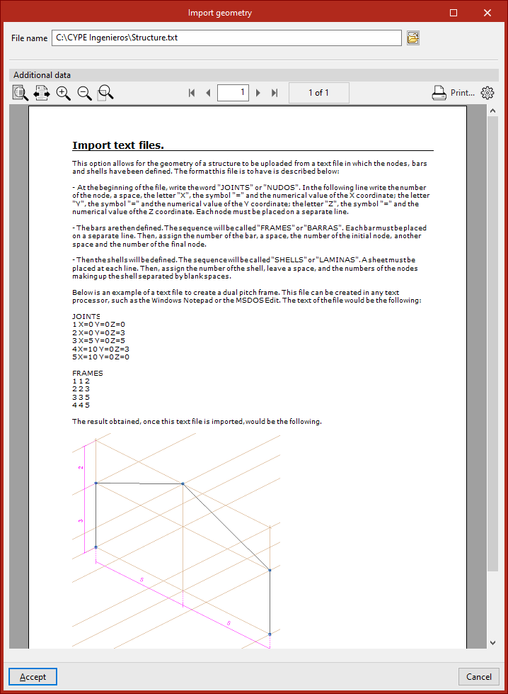
The program indicates whether the "Reading finished correctly" and asks "Do you wish to import read data".
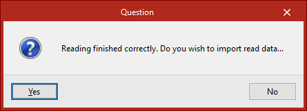
If you select "Yes", the program will import the elements into the model.
| Note: |
|---|
| The dimensions of the imported structure will depend on the unit system used (under "Settings", "Units"). The values in the .txt file will be treated as being expressed in the selected units. |
From this point onwards, the cross-sections of the beams and slabs, the loads, and the external and internal connections must be defined in order to complete the project.
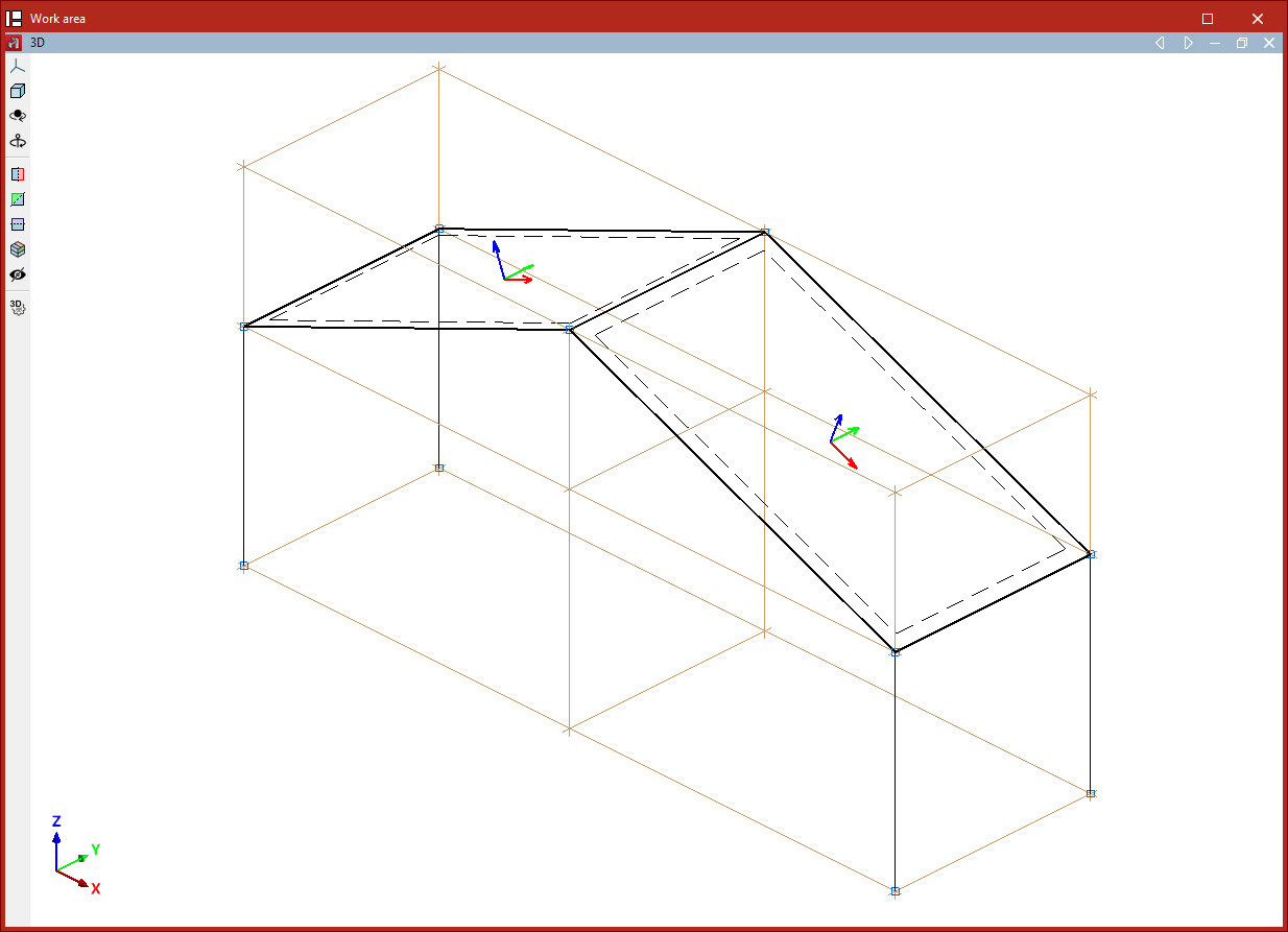
Layout of the elements imported into the model
If the text file is imported into a project that is not empty, the program will allow you to choose the position of the imported elements:
- If you select "Import to the position specified in the file", the program will load the data at the coordinates entered in the file.
- If "Select reference point for import" is displayed, you must select that point by clicking on it with the left mouse button directly in the model view.
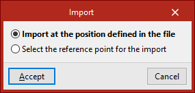
Table of contents
Complete your CYPE 3D journey by exploring the other available sections:
- Introduction
- Start: creating new projects, workflows, and examples
- Setting the work environment
- Setting the job data
- Defining the structure’s geometry
- Editing the properties of structural elements
- Entering and editing loads on the structure
- Designing and analysing connections
- Analyses, checks, and results
- Defining and editing reinforcement
- Designing and analysing foundation
- Printing documents and exporting data