
Options in the "Analysis" tab
The upper tab "Analysis" (accessible in the lower tab "Structure") contains the options for analysing and designing the elements in the structure, as well as those for consulting the results of the analysis, such as displacements, forces and checks carried out.
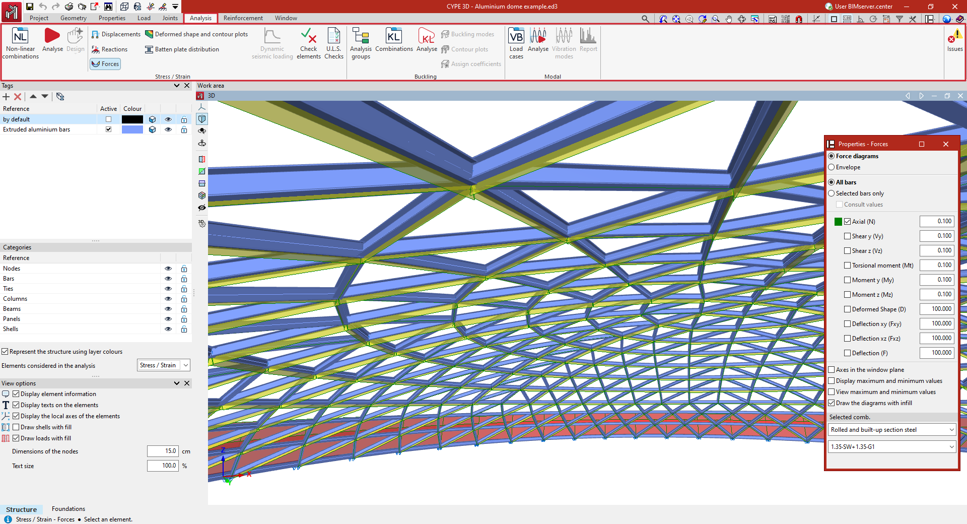
The "Stress / Strain" group, on the left, contains the options for carrying out the stress-strain analysis of the structure and consulting its results. It includes:
- The options for defining non-linear combinations, carrying out the analysis and design of the structure, and the design of special elements such as joints, columns, beams or the thickness of the fireproof cladding.
- The options for checking the node displacements, support reactions, bar forces and integration strips, deformation and contour plots, and the grid, as well as to obtain the list with the results of the seismic action, to carry out the checking of the elements and to obtain detailed reports of the ultimate limit state (E. L.U.) corresponding to the selected code.
Further to the right are the following blocks of options, which allow for more advanced, specific analyses:
- The "Buckling" group contains the options for linear buckling analysis, which determines the critical load factors and buckling deformations of the structure for each combination analysed.
- The "Modal" group contains the options for modal vibration analysis of the structure, which determines the frequencies, periods and modal shapes, the participation coefficients and the percentages of mobilised mass in the analysis directions for each mode.
- The "Pushover" section, the options that enable a pushover analysis to be carried out, including the definition of load cases and the control node, and the calculation of results such as the capacity curve and the performance point.
The program also includes a tool to display or hide "Issues" on the screen in the form of warning or error messages.
Defining non-linear combinations
Load combinations used in the non-linear analysis can be entered, generated and/or edited using the following option, which is available in the "Stress / Strain" group of the top toolbar, within the "Analysis" tab (under the "Structure" tab).

Non-linear combinations
As it is not possible to overlay loadcases in non-linear analysis, a model analysis must be carried out for each load combination to be studied.
The "Non-linear combinations" option allows you to define the combinations you wish to analyse.
Clicking on it opens the "Non-linear combinations" window.
Load combinations are defined based on the loadcases specified in the "General data" section of the project.
Here, the program allows you to define the combinations to be analysed in three different ways.
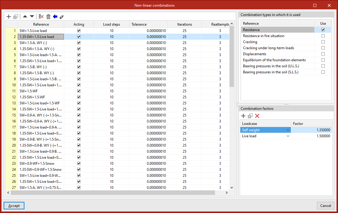
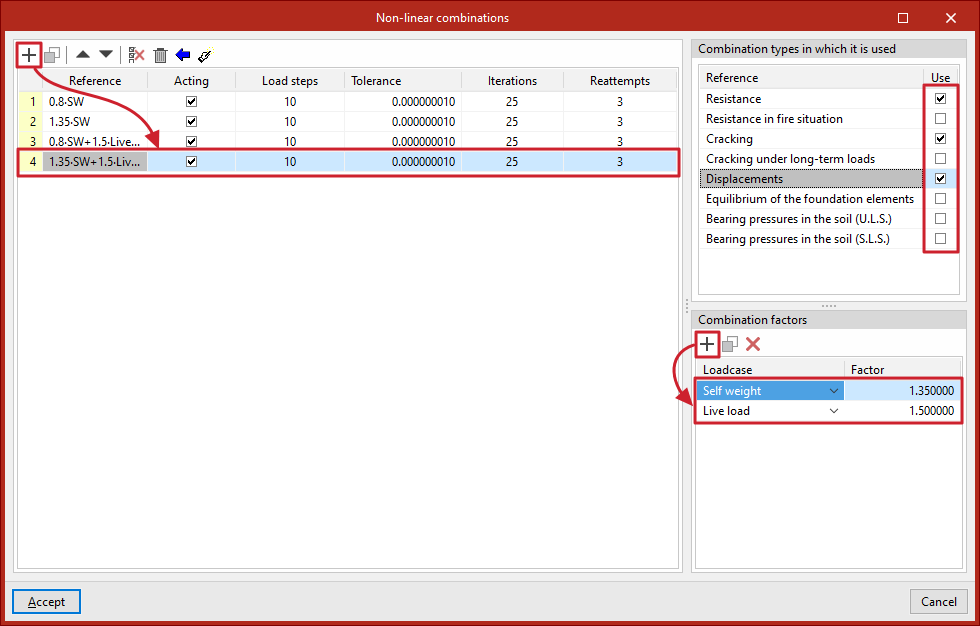
Entering combinations manually
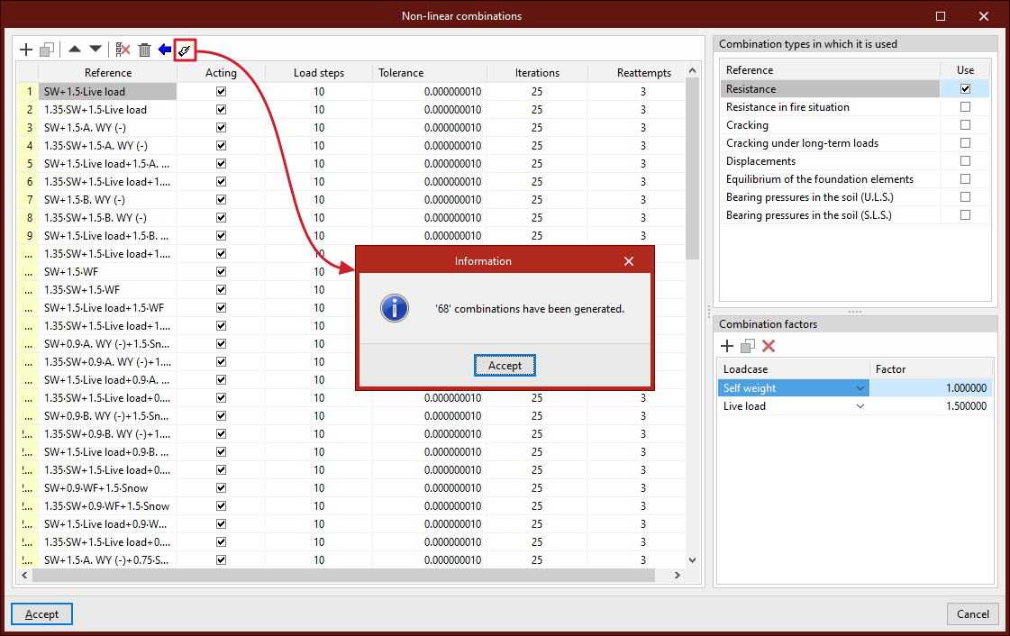
Load combinations for non-linear analysis can be added manually to the list on the left-hand side using the options on the top toolbar.
Each combination is defined as follows:
- The "Reference" is generated automatically based on the loadcases and combination factors defined below
- You can indicate whether the combination is "Acting" or not by ticking the box in the next column
- And the number of "Load steps", the "Tolerance" value, the number of "Iterations" used in the analysis, and the number of "Reattempts" are defined
Next, on the right-hand side, for each combination entered in the list, tick the box next to each of the "Combination types" in which it will be used to check structural elements, such as the following:
- Resistance
- Resistance in fire situation
- Cracking
- Cracking under long-term loads
- Displacements
- Equilibrium of the foundation elements
- Bearing pressures in the soil (U.L.S.)
- Bearing pressures in the soil (S.L.S.)
Further down, the "Combination factors" are defined by entering the value for the "Factor" for each "Loadcase" of the model selected from the drop-down menu.
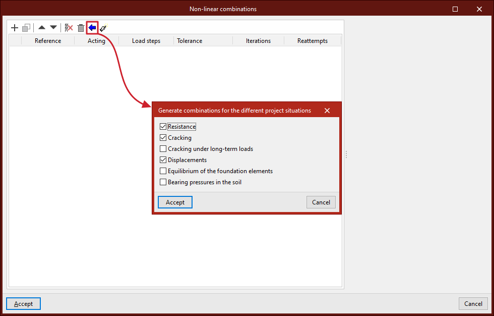
Generating combinations based on the loadcases defined in the project
Combinations for nonlinear analysis can be defined by automatically generating all possible combinations based on the conditions defined in the project.
To do this, click the "Generate combinations for the different project situations" button at the top of the list of combinations. In the pop-up window, select the project loadcases from which you wish to retrieve the information, which include the following:
- Resistance (optional)
- Cracking (optional)
- Cracking under long-term loads (optional)
- Displacements (optional)
- Equilibrium of the foundation elements (optional)
- Bearing pressures in the soil (optional)
To apply the settings, click "Accept". The program will generate all combinations of the selected loadcases, automatically adding the necessary entries to the list, marking the combination types in which they are used, and entering the corresponding combination factors.
Generating combinations based on the results of the linear calculation
If the structure has been analysed, you can use the "Generate combinations from the results of the linear analysis" option at the top of the list of combinations.
This option allows you to automatically add to the list those combinations from the linear stress-strain analysis for which a non-linear analysis needs to be performed.
Of all the combinations generated from the defined loadcases, the program will retain those that meet this requirement, adding the entries to the list, marking the types of combination in which they are used, and entering the corresponding combination factors for each loadcase.
Analysing the structure, checking and designing sections
The analysis, checking, and automatic design of the sections and connections in the structure is carried out using the "Analyse" option, available in the "Stress/Strain" group in the top toolbar, under the "Analysis" tab (in the "Structure" tab):

Analyse
Clicking this option opens the "Analysis" window, where various analysis parameters can be configured under the following sections:
Analysis to be carried out
This section appears if nonlinear combinations have been defined and/or nonlinear elements have been inserted in the model. In that case, the following analyses can be activated. One or both of the following must be selected:
- Linear stress/strain analysis
Performs a linear analysis of the structure. Nonlinear elements are treated as linear for this analysis. - Nonlinear stress/strain analysis
Performs a nonlinear analysis of the structure.
A nonlinear analysis can be carried out without having defined nonlinear combinations in advance. In this case, the program will determine which combinations need to be analysed based on the results of the linear analysis, displaying the message:
"The program will automatically generate nonlinear combinations after the linear analysis."
If nonlinear combinations have been defined, a checkbox will appear allowing you to "Update non-linear combinations after the linear analysis".
The checking of the bars is performed using the results available after the analysis. If both linear and nonlinear results exist, the program will combine them according to the types of combinations assigned to each element.
If no nonlinear combinations are defined and no nonlinear elements are inserted into the model, this section will not appear, and the program will default to a linear stress/strain analysis.

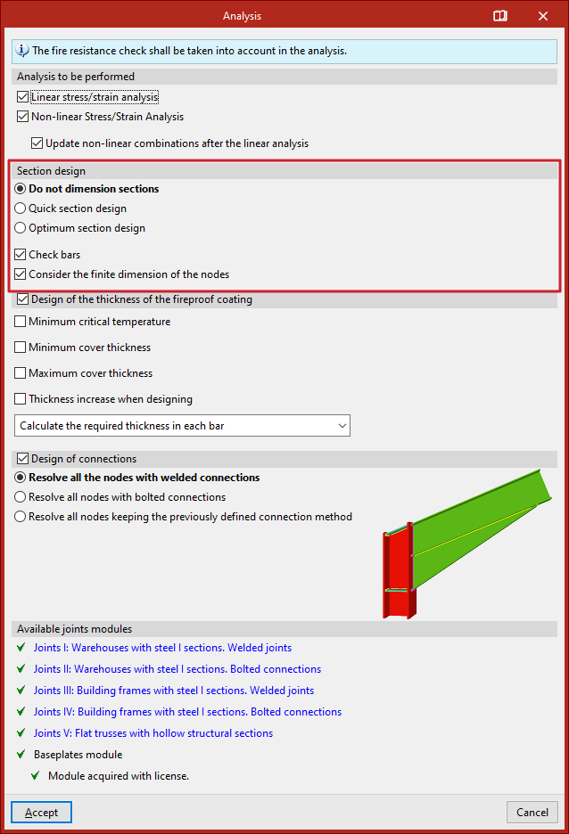
Section design
In the "Section design" section, the program's behaviour is specified in case any bars do not comply.
- If "Do not dimension sections" is selected, the program will analyse the structure but will not make any changes to the input sections.
- Selecting "Quick section design" instructs the program to check each bar against the internal forces obtained during analysis. If a section fails, it is replaced with the next larger section from the same series that passes all checks. A new analysis is then performed. This process is repeated iteratively until all bars comply or the largest section in the series is reached.
- With "Optimum section design", any failing section is replaced with the next in the series (regardless of whether it complies or not), followed by a new analysis. This method is slower but reduces the risk of assigning excessively large sections.
For either method, you may specify whether the design should be carried out "Using sections of the series greater than the current section" or "Using all the sections of the series".
If the "Check bars" box is checked, the program will verify compliance of all bars. If unchecked, only internal forces and displacements will be analysed.
The "Consider the finite dimension of the nodes" option allows the program to automatically adjust bar lengths by subtracting connection dimensions at nodes. This should be enabled if an analysis is going to be carried out on the connections in the structure.
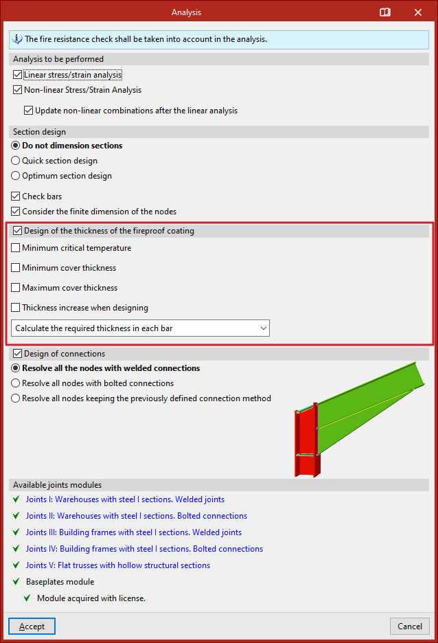
Design of the thickness of the fireproof coating
If fire resistance checking has been enabled in the "General data" and a specific fire protection coating has been selected, the "Design of the thickness of the fireproof coating" can be carried out for the bars. The following options are available:
- Minimum critical temperature
Defines the minimum critical temperature for sizing the fire protection thickness. - Minimum cover thickness
Sets a minimum value for the coating thickness. - Maximum cover thickness
Defines a maximum coating thickness. - Thickness increment when designing
- Sets the increment used by the program during the design process.
- Cover unification
In this dropdown, you select how the calculated cover thickness is applied:- Calculate the required thickness in each bar
Assigns the exact required thickness to each individual bar. - Match the thickness of all the bars
All bars will receive the thickness required by the most unfavourable bar. - Match the thickness of all the bars with the same section
Bars with the same cross-section will receive the thickness required by the most unfavourable among them. - Match the thickness of the bars belonging to the same the group
- Bars in the same group will receive the thickness required by the most unfavourable bar in the group.
- Calculate the required thickness in each bar
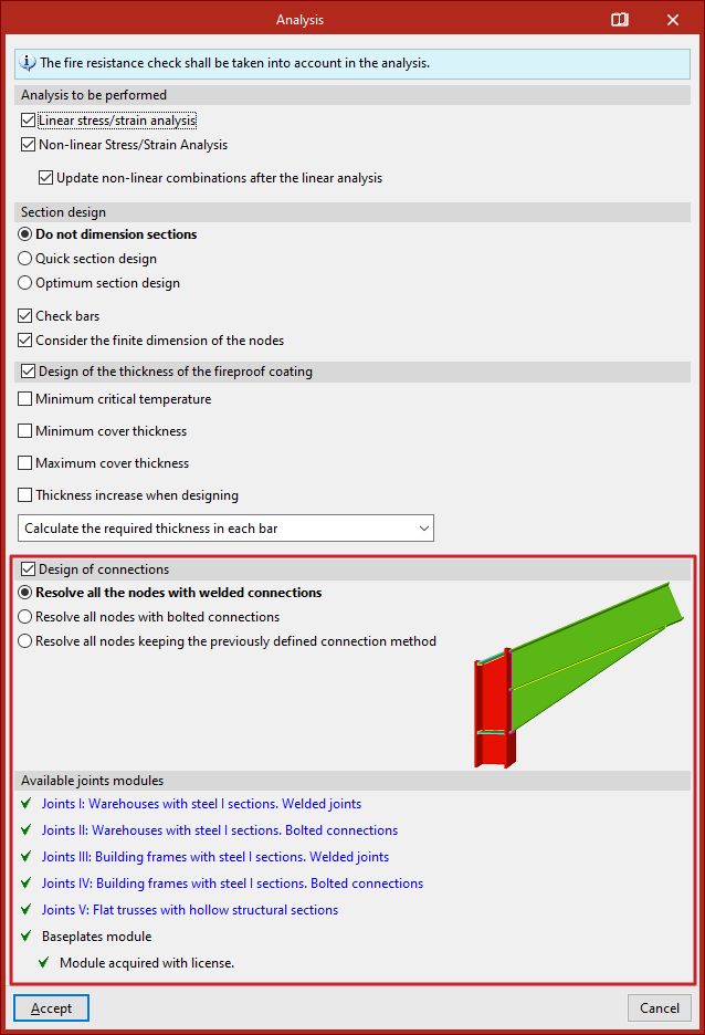
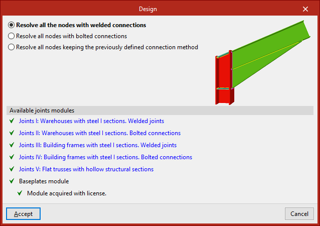
Design of connections
If connections have been generated, the "Design of connections" option can be activated to include them in the analysis process.
In the selector, choose whether to "Resolve all the nodes with welded connections", "Resolve all nodes with bolted connections", in which case you can also enable the "Use prestressed bolts" checkbox or "Resolve all nodes maintaining the previously defined joint method".
Available joints modules
In the last section, the program displays the "Available joint modules" included in the license.
You can click any of the links to consult the set of joints that can be designed within each module.
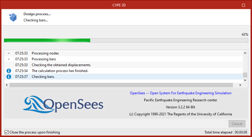
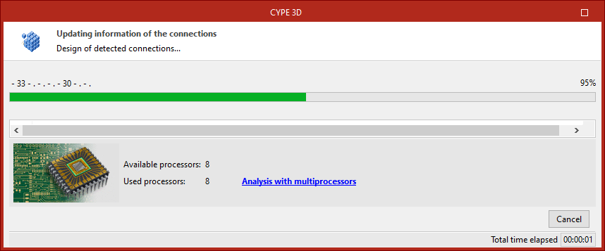
Design process
After clicking "Accept", the program launches the analysis window, which displays the different stages of the process, including component discretisation, equation solving, bar checking, and connection design.
It also displays information about the OpenSees engine (Open System for Earthquake Engineering Simulation) used during nonlinear analysis, or—if not performing a nonlinear analysis—the number of "Available processors" and "Used processors". In some stages, the program can use additional processors if a multiprocessor license is available.At the bottom of the window, you'll find the "Close" option and a checkbox "Close the progress upon finishing", which closes the analysis window automatically when the process is finished. The "Total time elapsed" since the start of the analysis is also displayed.
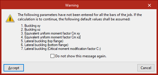
| Note: |
|---|
| Before launching the analysis, the program will display a "Warning" listing any missing parameters (e.g. buckling or lateral buckling data) for the bars. If this warning is accepted, the program will proceed using default values. |
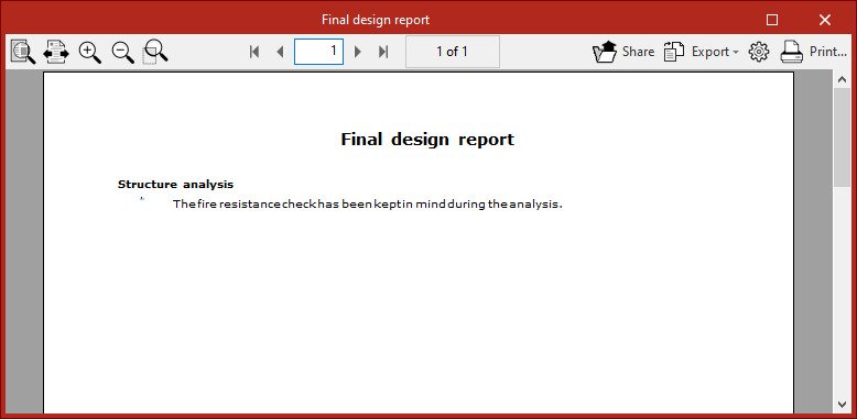
Final design report
At the end of the analysis process, the program displays the "Final design report" with any issues detected.
| Note: |
|---|
| You can select the "Issues" option in the toolbar under the "Analysis" tab to visually locate problems in the model. Hovering the mouse cursor over each issue will show a message describing the problem. |
Designing and updating joint analysis results
To carry out only the design and update of the structural connection analysis results within the program, once they have been created, use the options in the "Design" menu. This menu is located at the top of the "Analysis" tab interface (within the "Structure" tab).

Alternatively, you can perform a combined analysis of the structure and connections simultaneously via the "Analysis" option, and then tick the "Connection design" box in the pop-up window.
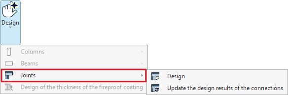
Options in the "Dimension" menu
To calculate joints only, open the "Desing" menu and then select the "Joints" submenu.
This menu is only available if joints have been entered or generated in the model and the structure has been analysed.
Design
The "Design" option allows the program to design all previously defined joints. This allows the structure and the joints to be analysed separately.
The drop-down menu allows you to choose whether to "Resolve all nodes with welded connections" or "Resolve all nodes with bolted connections" – in the latter case, the checkbox below for "Use prestressed bolts" is selected – or "Resolve all nodes whilst keeping the previously defined connection method".
In the final section, the program displays the "Available joint modules" included in the license. You can click on any of the links to view the range of joints that can be analysed using each module.
Finally, click "Accept".
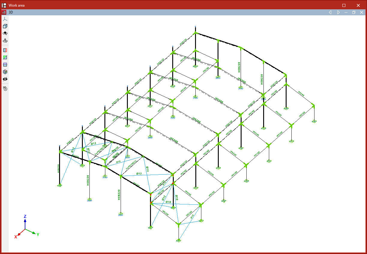
Update the analysis results for the joints
If any of the joints have been edited, the program will display them in yellow on the model, pending the update of the analysis results.
In this case, the other option in the "Connections" submenu is used, which serves to "Update the design results of the connections" in the structure and their rotational stiffnesses.
When this is done, the connections turn green if they pass all the checks, and red if they fail any of the checks.
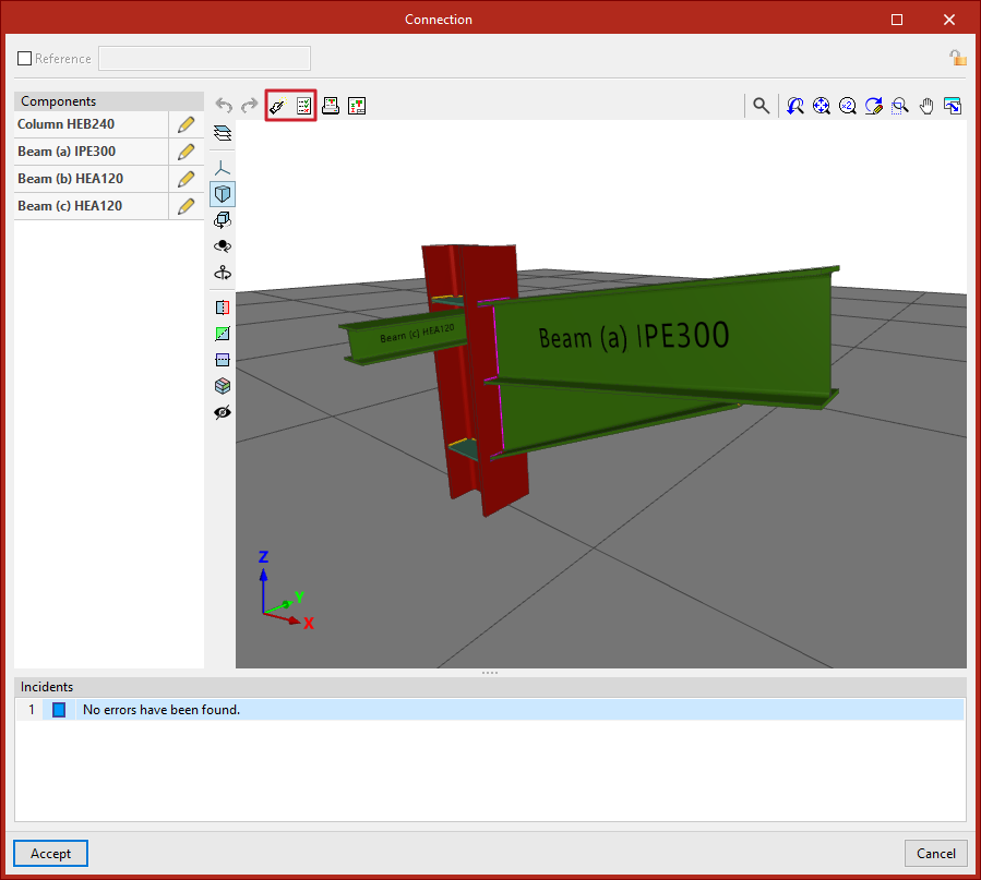
Individual design and verification
The results can also be designed or updated individually for each type of joint.
To do this, open the "Joints" tab, select "Edit" and left-click on the joint in the model.
Next, in the editing window, use the "Design" option at the top if you want to design the selected joint individually.
If any changes have been made, select "Check" to update the analysis results and verify that the checks have been passed.
Checking displacements and rotations in the nodes
The displacements and rotations at the nodes after the analysis of the structure can be viewed with the following option, which is available in the "Stress / Strain" group of the upper toolbar in the "Analysis" tab (in the "Structure" tab).

Displacements
The "Displacements" option is used to check the displacements and rotations of the two end nodes of a bar.
By left-clicking on a bar, the program will display on the screen the displacements and rotations in the three directions of space of each of the end nodes.
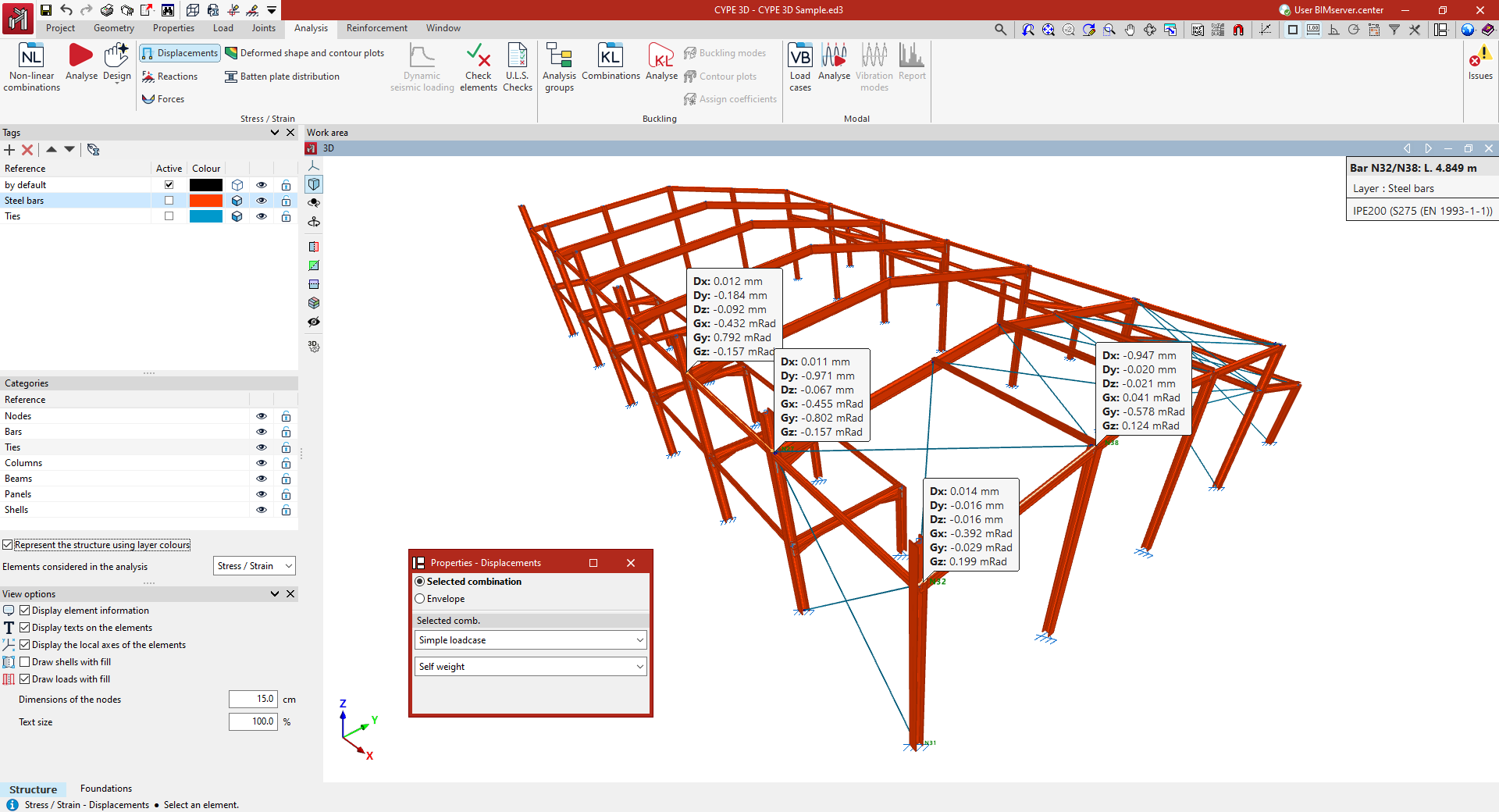
The values shown refer to the global axes of the model. The positive sign of a displacement refers to the positive direction of each axis. On the other hand, a rotation referred to an axis indicates a rotation around that axis, and is positive in a counter-clockwise direction.
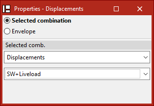
In the "Properties - Displacements" dialogue box that appears, there are two options to choose from:
- If "Selected combination" is chosen, the loadcase or combination of loadcases to be checked must be specified in the drop-down menus below:
- By selecting "Simple loadcase" in the first drop-down menu, a specific loadcase can then be chosen from those available.
- By selecting the "Displacements" group in the first drop-down menu, a specific combination of loadcases belonging to this group can then be chosen.
- The groups of loadcase combinations associated with the different materials ("Rolled and reinforced steel", "Cold formed steel", "Wood", "Aluminium" and "Concrete") are also available.
- If "Envelopes" is chosen, the program shall display the maximum and minimum values of the envelope of loadcase combinations. These values cannot be simultaneous, i.e. the maximum displacement or rotation value in a given direction does not have to occur simultaneously with the values in another direction.
To hide the displayed information, left-click on the bar again.
Checking reactions in the support
Checking the support reactions after analysing the structure is done with the following option, available in the "Stress / Strain" group of the upper toolbar in the "Analysis" tab (in the "Structure" tab):

Reactions
The "Reactions" option is used to display the reactions on the external supports or links, i.e. the forces exerted on the modelled structure by the terrain or the supporting elements.
By left-clicking on a defined node with external linking, the program will display the forces and reaction moments in the three spatial directions.
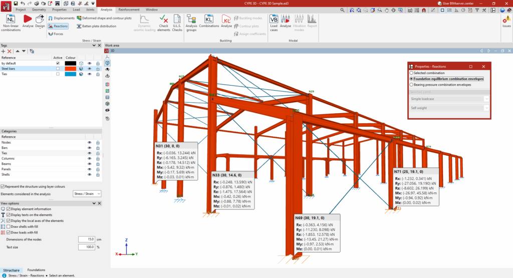
The values of the reactions are referenced to the global axes of the model. A reaction force with a positive sign follows the positive direction of the axis. Moments referenced to an axis indicate a rotation about that axis, being positive in the counterclockwise direction.
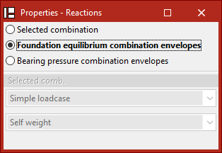
In the "Properties - Reactions" dialogue box that appears, there are three options to choose from.
- By choosing "Selected combination" the particular loadcase or combination of loadcases to be checked is specified.
- By selecting "Simple loadcase", a specific loadcase can be selected from the drop-down menu to check the support reactions associated with that loadcase.
- The other options in the drop-down menu correspond to the different groups of loadcase combinations defined in the model ("Displacements", "Rolled and reinforced steel", "Cold formed steel", "Timber", "Aluminium", "Concrete", "Concrete in foundations" and "Ground bearing pressures").
- By choosing "Foundation equilibrium combination envelopes", the maximum and minimum values of the group of combinations used in the equilibrium checks of the foundation elements are displayed.
- Selecting "Bearing pressure combination envelopes" displays the maximum and minimum values of the group of combinations used in the ground stress checks.
The values do not have to match between the latter two, since the majorisation and combination coefficients are different for each combination of loadcases.
Finally, to hide the displayed information, left-click on the support again.
Check forces
The force values after the analysis of the structure are checked with the following option, available in the "Stress / Strain" group of the upper toolbar, in the "Analysis" tab (in the "Structure" tab).

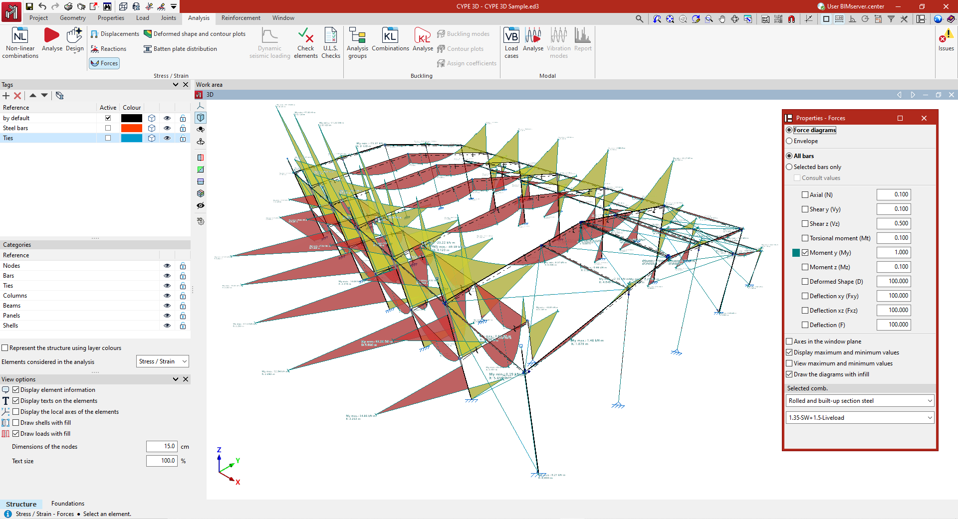
Forces
The "Forces" option can be used to draw on screen the forces, deflection, strain and tension graphs of both the bars and the integration strips of the sheets.
Force selection
In the "Properties - Forces" dialogue box that appears, the following options can be configured.
- If "Laws" is selected, the loadcase or combination of loadcases to be checked must be indicated in the "Selected combination" section at the bottom of the window. To do this, the program provides a choice between different groups of combinations in the drop-down menus.
- By selecting "Envelopes", the program draws the maximum and minimum values of the force envelope of all the combinations used in the analysis.
The bars to be checked are then selected.
- If "All bars" is checked, the selected force graphs will be drawn for all bars in the structure.
- If "Only selected bars" is checked, each bar must be clicked on for the force graphs to be drawn.
- By activating the "Check values" checkbox, the mouse cursor can be moved along the bars to display an information box with the values calculated at the indicated point.
Among the magnitudes that can be checked by activating the boxes in the central part of the dialogue box are the following:
- the "Axil", the shear and bending moment in the two directions ("Shear y", "Shear x", "Moment y" and "Moment z"), the "Torsional moment", the "Deflection xy" and "Deflection xz", which correspond to the two planes of the profile, and the total combined "Deflection";
- with the "Laws" and "All bars" options selected, it is also possible to display the "Deformed shape" of the structure;
- and if the "Envelopes" display is activated, in addition to the stresses and deflection, the program allows users to consult information on the stress-strain ratio. This graph can examine which regions of the bars are compliant or non-compliant.
Each of the graphs is drawn in a different colour. This makes it possible to distinguish the graphs on the screen when several graphs are activated at the same time.
In addition, to the right of each of the magnitudes, the scale factor can be modified to change the size of the representation of the graphs in the viewer.
Other configuration options
Below are the following options for configuring the display of the force laws:
- The "Axes in the window plane" option displays the force graphs in a coordinate system with the axes constructed on the window plane. This can be useful to make the plots visible in some views.
- The "Draw maximum and minimum values" option adds on each graph the information of the maximum and minimum values they reach, as well as the position at which they occur.
- Finally, if only one graph is activated, "View maximum and minimum values" can be selected. In this case, the mouse cursor must be moved over the bars so that the program displays the maximum and minimum values in each one of them.
- It is also possible to configure the display of the force diagrams so that they are shown filled with colour by activating the "Draw the diagrams with infill" checkbox.
- If the "Display stress using contour lines" option is deactivated when viewing the stress/strain graph, the bar sections in which the stress complies with the normative limitations are shown in green, and those that do not comply are shown in red. If "Display stress using contour lines" is activated, the values of the stress graph are detailed using a range of colours, showing a value between zero and the maximum stress value. The legend at the bottom of the display allows these colours to be interpreted.
Checking the deformed shape and contour plots
The deformed shape and contour plots of the structure can be checked after carrying out the analysis using the specific option available in the "Stress / Strain" group on the top toolbar of the "Analysis" tab (within the "Structure" tab).

Deformed shape and contour plots in the active window
After clicking the "Deformed shape and contour plots" option, a pop-up window appears where you can view the deformed shape and contour plots of the elements visible in the currently active window.
The display settings for the different windows showing the deformed shape and contour plots are associated with each structural view in CYPE 3D. These settings are retained even when exiting the contour plot interface, and remain until the program is closed.
To exit the visualisation window, click the "Finish" option in the top-left corner.
"Options" window
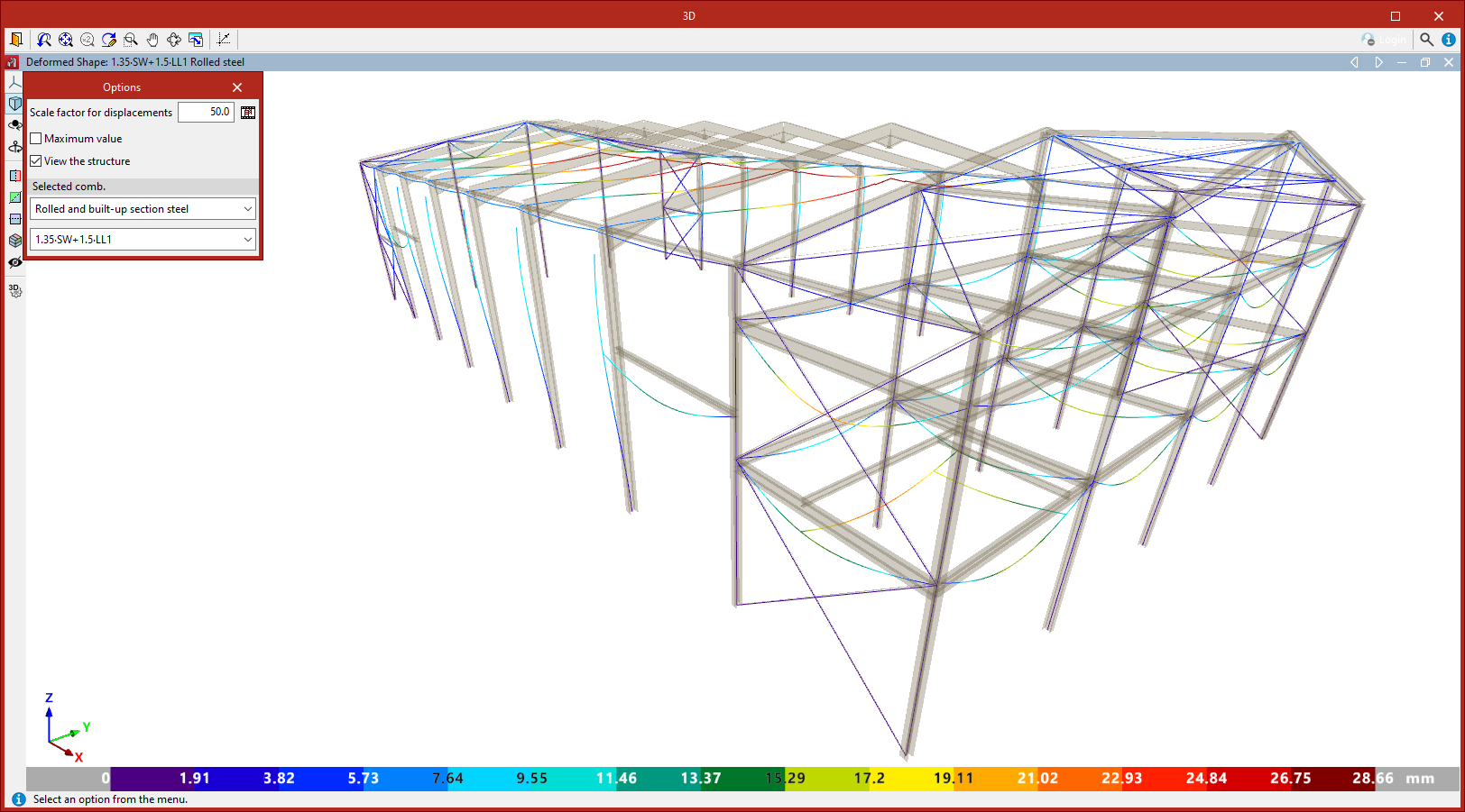
Clicking the "Deformed shape and contour plots" option also opens the "Options" window, where you can configure what information to display:
Display options
- At the top, enter a "Scale factor for displacements" to adjust the deformation scale shown in the viewer, making it easier to interpret.
- Further to the right, pressing the "Animation" option generates an on-screen animation of the structure’s deformed shape caused by the selected combination, starting from the undeformed position.
- If contour plots of shells are displayed, you can also change the "Colours for the representation of contour plots" by selecting a colour scheme from the available options using the button in the top-right corner of the "Options" window.
- By enabling the relevant checkbox, you can enter a "Maximum value" to be represented by the colour scale in the deformed shape. Any values above the specified limit will be displayed in grey.
- If the "View structure" checkbox is activated, a semi-transparent, realistic view of the structure is displayed alongside the deformed shape.
Selecting the loadcase or combination
In the "Selected combination" section at the bottom of the "Options" window, you must specify the particular load case or combination to view.
You may choose a "Single load case", selecting one from the dropdown list to view the deformed shape and contour plots associated with it.
The remaining dropdown options correspond to the different groups of load combinations defined in the model.
Checking the values at each point
In the top-right corner of the window is the "Check" option. After clicking it, you can move the pointer over elements of the structure to view values associated with each point.
Checking the deformed shape
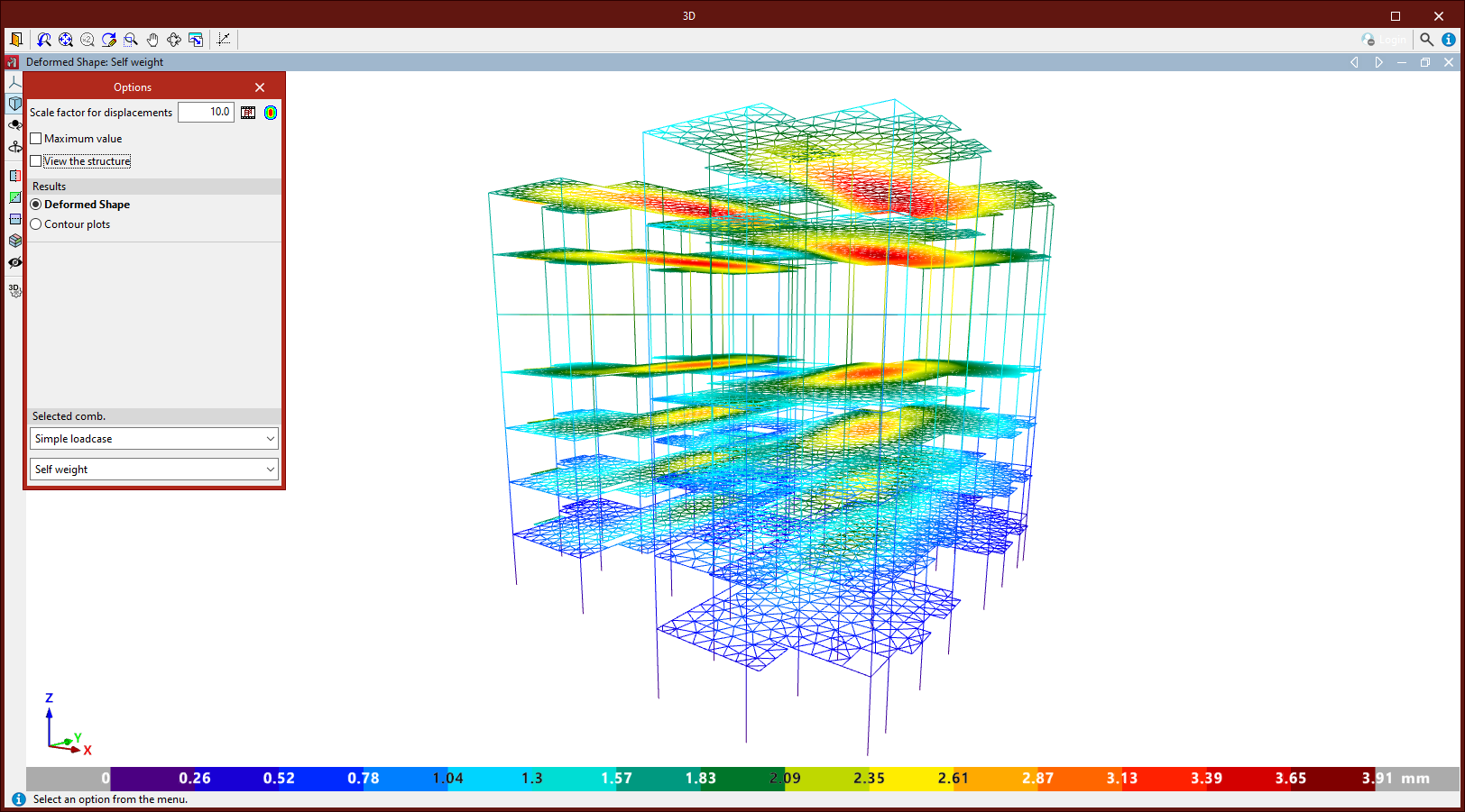
The "Result" section of the "Options" window only appears if shells have been entered into the structure and are visible in the active window.
Here, you can choose whether to display the "Deformed shape" of the structure or "Contour plots" of the shells.
If "Deformed shape" is selected, the deformation of the structural elements is shown for the selected combination.
If no shells have been entered or are not visible, the program defaults to displaying the deformed shape.
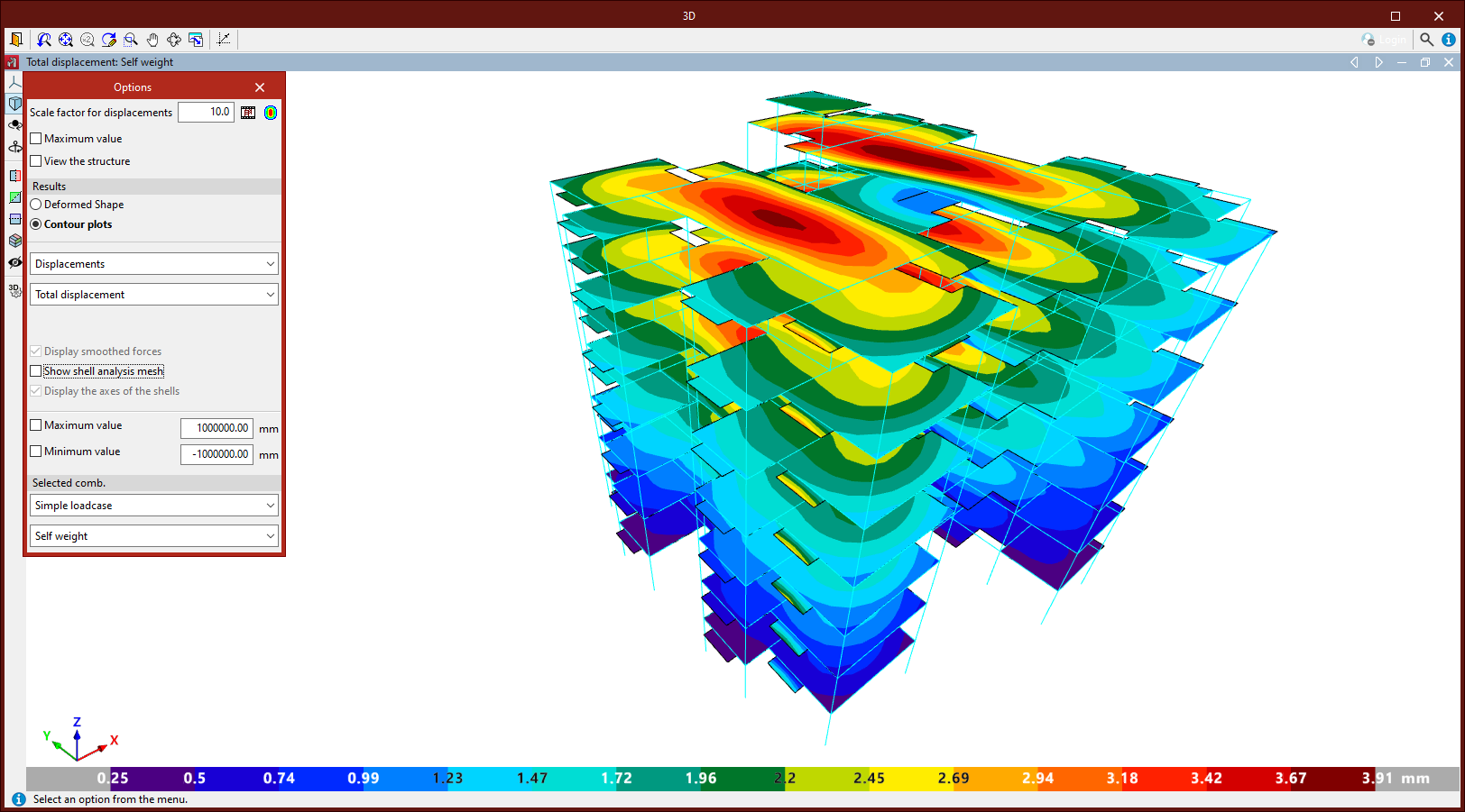
Checking the contour plots on shells
Selecting "Contour plots" in the "Results" section of the "Options" window allows you to view various types of shell element data through contour plots, depending on the dropdown selections:
- Selecting "Displacements" lets you view the "Total displacement", as well as displacements and rotations about the global X, Y, or Z axes.
- Under "Forces", you can view axial forces in X, Y, and XY, bending moments in X, Y, and XY, and shear forces in X and Y. These refer to the local axes of the shell.
- Under "Stresses", you first choose whether to view data from the "Top face", "Bottom face", "Maximum of both faces", "Minimum of both faces", or "Absolute maximum of both faces".
Then, in the second dropdown, you can choose from normal stress in X or Y, shear stress in XY, XZ, or YZ, "Maximum normal stress", "Minimum normal stress", "Von Mises stress", or "Maximum shear stress". Again, these refer to the local axes of the shell.
Additional options include "Show smoothed forces", "Show mesh", "Draw shell axes", all activated via checkboxes at the bottom.
You can also enable the "Maximum value" and "Minimum value" checkboxes to define the display range limits for contour plots. Values outside these limits are shown using the colours at the extremes of the selected colour scheme.
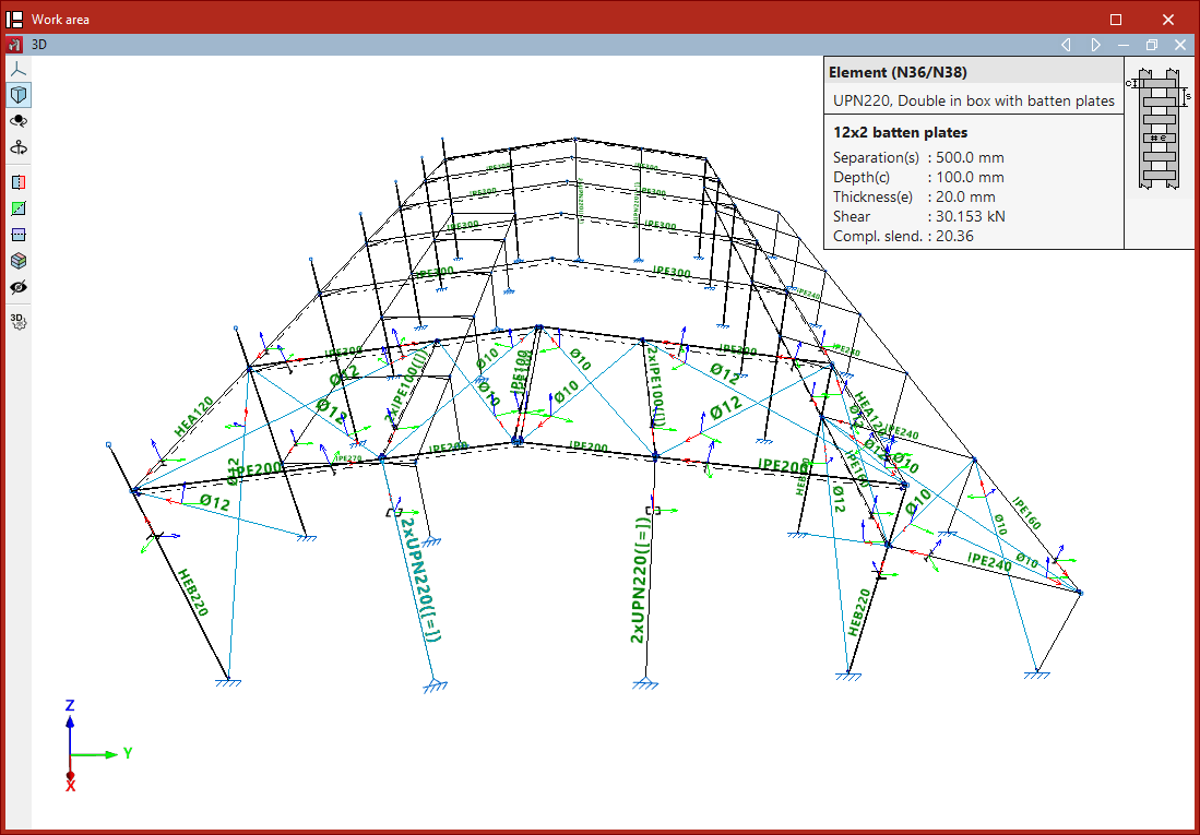
View the batten plate distribution in the "Analysis" tab
The "Batten plate distribution" data obtained from the analysis can be viewed using the specific option available in the "Stress / Strain" section of the top toolbar, within the "Analysis" tab (under the "Structure" tab).

Batten plate distribution
When analysing the structure, the program determines the dimensions of the brackets in accordance with regulatory specifications.
To view the results, select the "Clip" option and left-click on a profile that has been defined using batten plates.
The program thus reports the total number of batten plates obtained, their "Spacing", "Edge", "Thickness", the design "Shear" and the supplementary slenderness ratio ("Compl. slend.") provided by this batten plate layout, which affects the buckling analysis of the bar.
The information box that appears when you select this option provides a guide to help you understand these values.
| Note: |
|---|
| The analysis of composite elements is carried out by verifying each of the individual sections that make them up. These sections are checked for the forces analysed from those acting on the composite element, according to its mechanical properties. For stability checks, the ideal mechanical slenderness ratio is used, obtained based on the slenderness of the element and a supplementary slenderness ratio that takes into account the spacing of the connections between the individual section. |
Obtaining the "Dynamic seismic loading" report
The report with the results of the "Dynamic seismic loading" calculation is obtained using the specific option available in the "Stress / Strain" group on the top toolbar, under the "Analysis" tab (within the "Structure" tab).

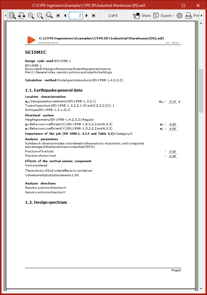
"Dynamic seismic loading" report
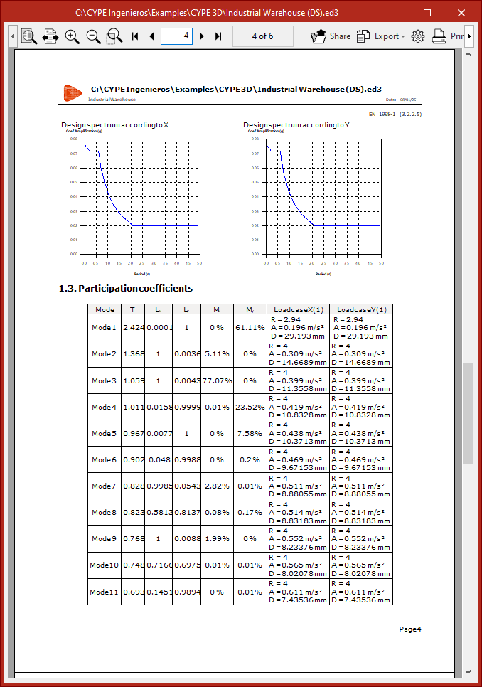
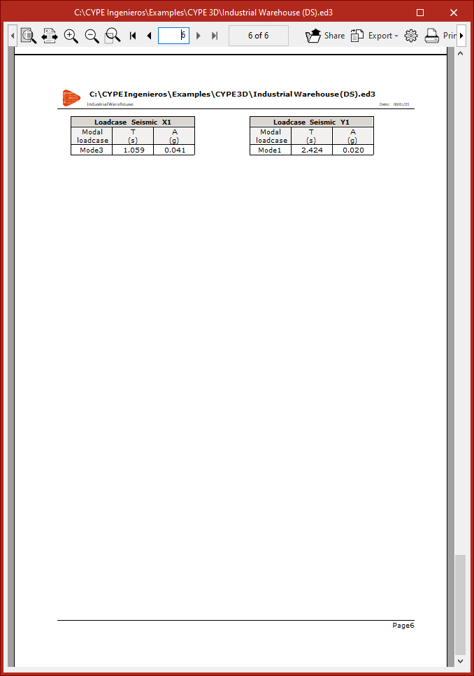
This report first displays the "Earthquake general data".
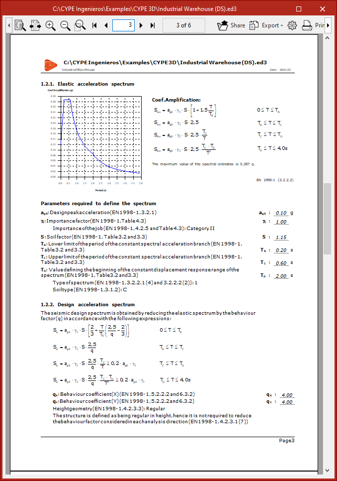
It then includes the definition of the "Elastic acceleration spectrum", the "Design spectrum in X", and the "Design spectrum in Y", indicating in each case the value of the "Participation coefficient" as a function of the "Period".
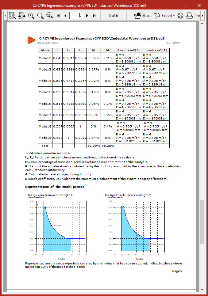
Next, a table is shown with the "Participation coefficients" and the "Percentage of mass displaced in each mode in each direction of the analysis" for each "Mode" of vibration.
The "Total" percentage of displaced mass should be a high and significant value, exceeding the minimum required percentage of displaced mass.
Finally, a "Representation of the modal periods" is shown over each design spectrum.
Checking structural elements
The "Check elements" option, found in the "Stress / Strain" group on the top toolbar of the "Analysis" tab, allows you to check all the elements of the structure after it has been analysed.

Checking elements
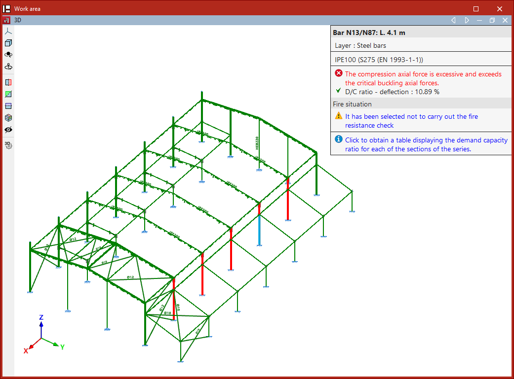
When you click on the option, elements that pass all checks are displayed in green. Those that fail any checks are shown in red, and elements with a warning are shown in yellow.
When you hover the pointer over the bars, the information box displays the resistance demand capacity ratios ("D/C ratio - resistance") and deflection utilisation factor ("D/C ratio - deflection") if their limits have been defined.
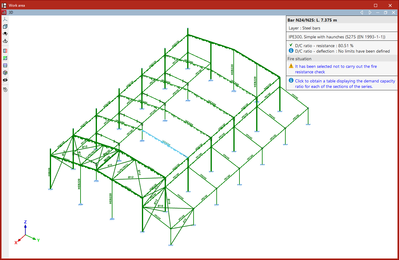
By left-clicking on a bar, a table is shown with the demand capacity ratios for all sections in the series.
| Note: |
|---|
| For bars of type "Column" or "Beam", the corresponding editor will appear instead of the table. |
In the section table, each "Section" shows its "Weight", the "Resistance" utilisation factor, the "Deflection" utilisation factor if defined, and any "Errors" it may have.
The program displays icons to indicate whether the section passes all checks or fails any of them.
When you select a section from the series and click "Accept", the program will assign that section to the selected bar.At this point, it is advisable to "Analyse" the structure again.

Ultimate limit state checks (U.L.S.)
The "U.L.S. checks" option, found in the "Stress / Strain" group on the top toolbar of the "Analysis" tab, allows you to view the ultimate limit state check reports for the elements of the structure after the analysis has been carried out.

U.L.S. checks
When you click on the option, the program displays bars that pass all checks in green, and those that fail any checks in red.
When you hover the pointer over each bar, an information box appears showing the section's demand capacity ratio ("D/C ratio").In the "Properties – U.L.S. checks" window that appears, there are two options:
- At the worst point
- At the indicated point

Ultimate limit state checks at the worst point
If "At the most unfavourable point" is selected, you must then select a bar by left-clicking on it.
This opens the "Checks" report for the bar. The report displays the results of each check at the point along the bar where that specific check is most unfavourable.
Each "Check" includes a "Status" label indicating whether it is "Verified" or not.
At the bottom, the relevant clause or article from the design code is shown, along with the detailed calculation carried out.
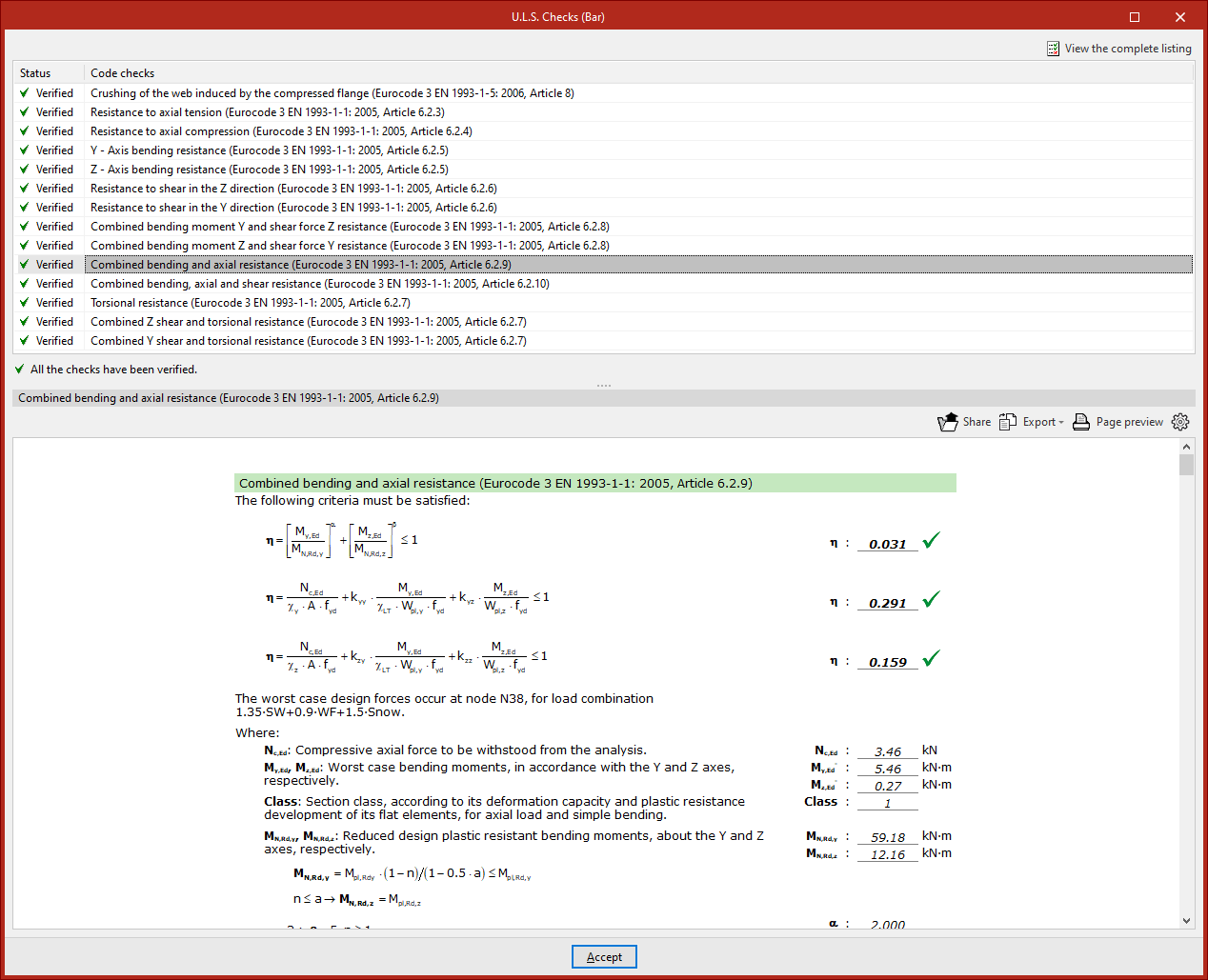
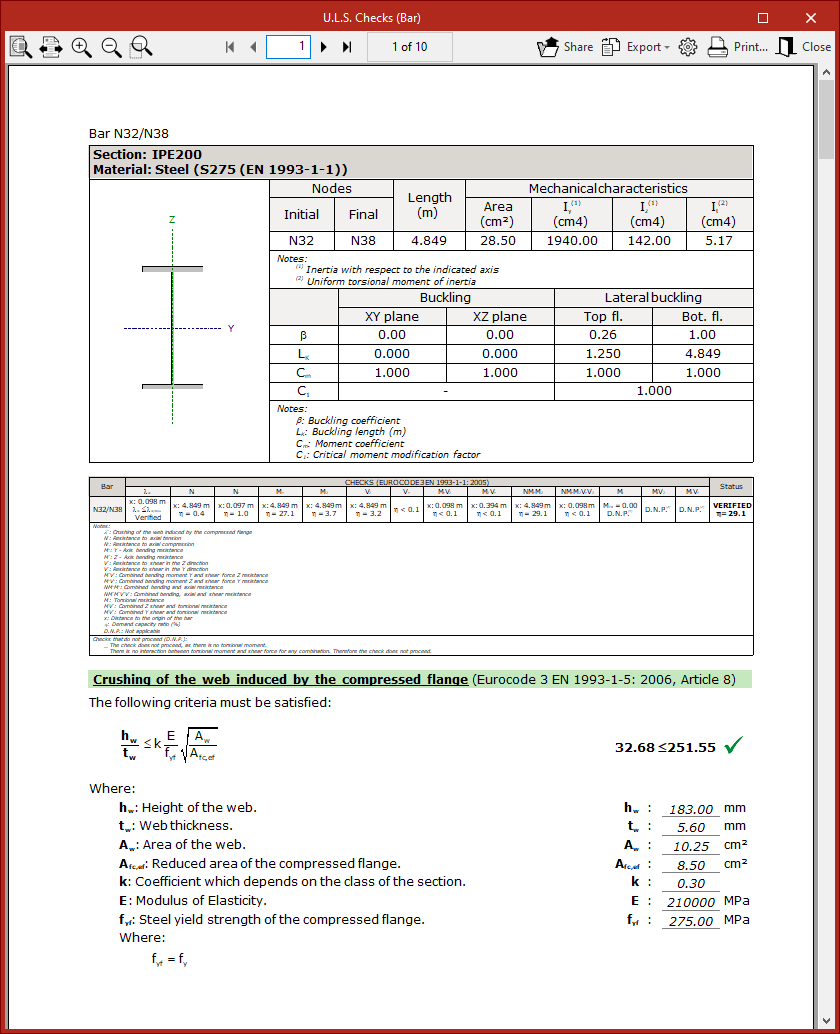
To obtain a detailed report of all checks, click "View full report" in the top right corner.
The information can be "Exported" in various formats (such as HTML, DOCX, PDF, RTF, or TXT), "Shared", or "Printed" using the options in the top right.
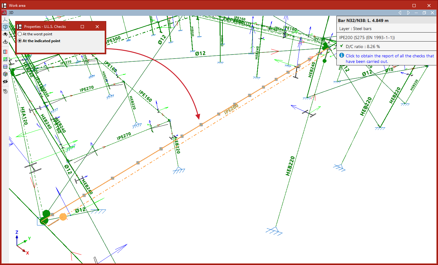
Ultimate limit state checks at the indicated point
The other available option, "At the indicated point", allows you to select a bar and then click on a specific point along it (from the available ones) using the left mouse button.
In this case, the report shows all checks at that particular section.
Right-clicking cancels the bar selection so you can inspect a point on a different bar.
Examples of buckling analysis in structures
Below are several examples of structures where the buckling analysis performed by the program can be applied, along with the sequence of steps for defining, analysing and viewing the results:
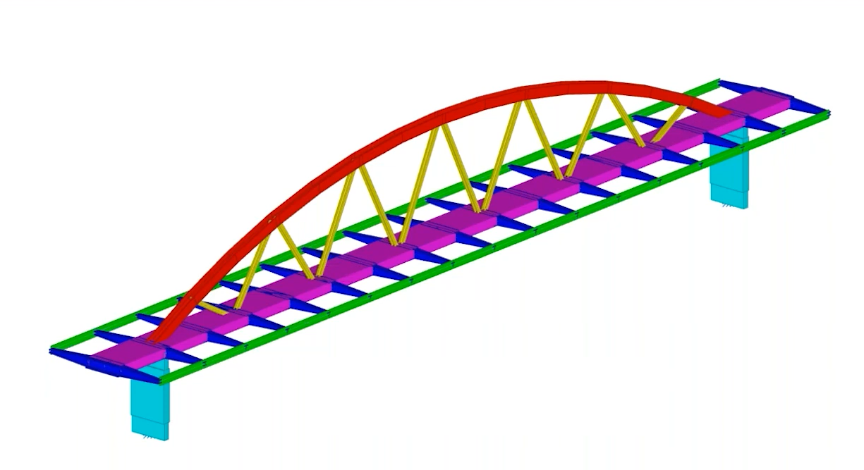
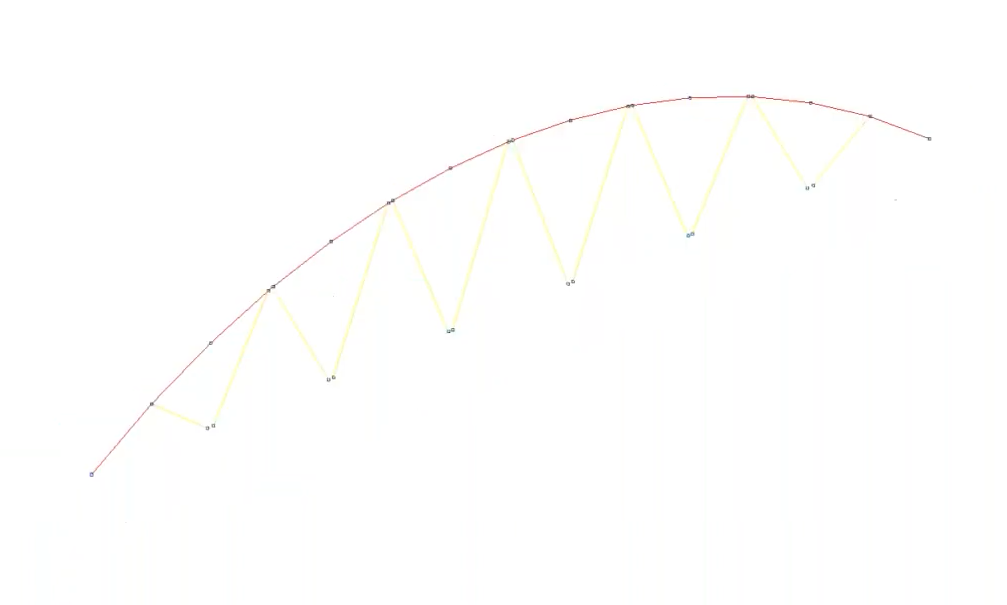
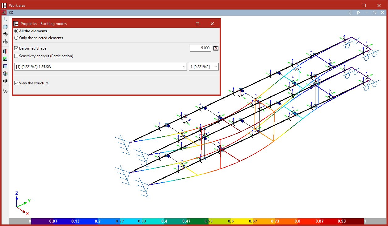
Arched steel walkway with a compressed top chord
The objective is to obtain and assign the buckling coefficients for the bars forming the compressed upper chord of the arch in a steel footbridge. This involves the following:
- The buckling analysis takes into account both the top chord bars and the lattice bars that brace them.
- The buckling analysis is carried out.
- Once the analysis has been completed, the deformation can be viewed for the various load combinations and buckling modes, along with the critical load factors obtained. Furthermore, a sensitivity analysis can be used to examine the participation coefficient of the bars in each combination and each mode. In this case, we can see that the bars in the upper chord account for the largest proportion; consequently, they are buckling.
- Buckling coefficients in both planes are assigned to the upper chord bars.
- In any of the checks carried out (such as the "Compressive strength" or "Slenderness limit" checks), the analysed buckling coefficient is taken into account.
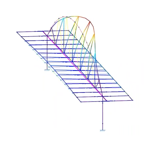
Strut between two retaining walls
The structure of this strut is subjected to compressive forces due to its position between two retaining walls.
The aim is to compare the structural performance of the components before and after carrying out the buckling analysis. To this end:
- The structure of the strut shown is defined by applying a buckling coefficient of 1 to the bars, thereby ensuring compliance with the regulations.
- From this point onwards, the buckling analysis begins. Firstly, ensure that all bars of the structure shown are included in the buckling analysis.
- The buckling analysis is carried out.
- Once the analysis has been completed, you can view the deformation, the critical load factors obtained and the contribution factor for each bar in every loadcase and mode.
- Buckling coefficients in both planes are assigned to the structural bars.
- The new buckling coefficients analysed may compromise the validity of the checks carried out on the bars before the buckling analysis.
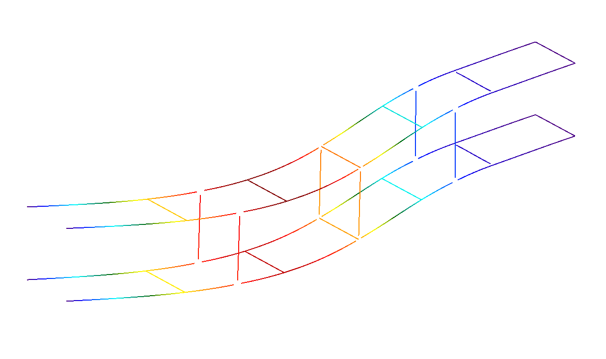
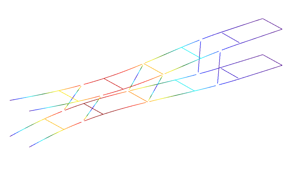
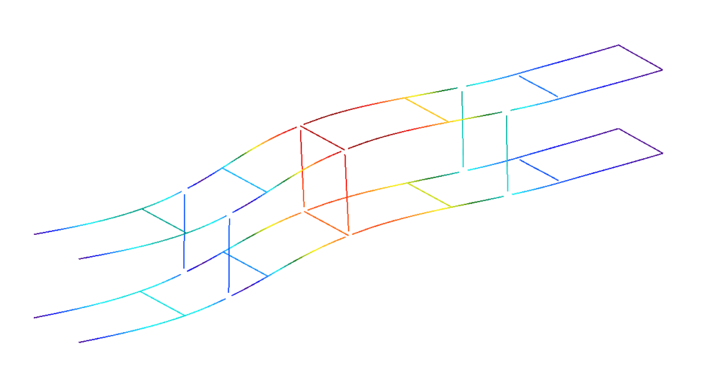
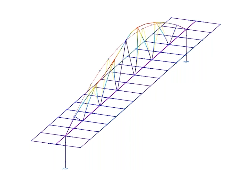
Buckling modes
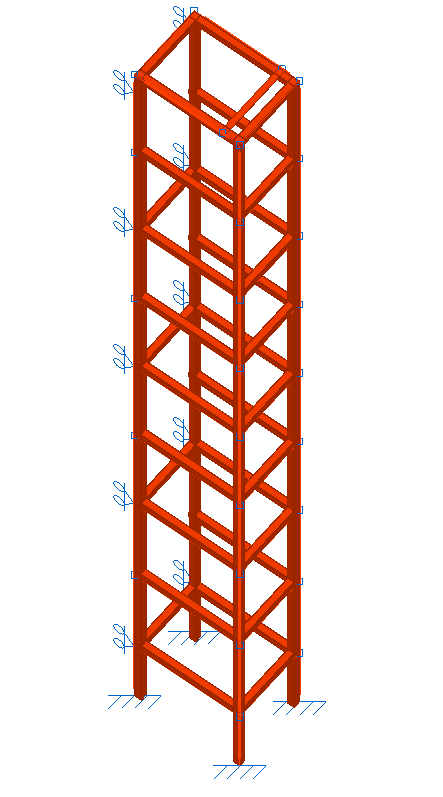
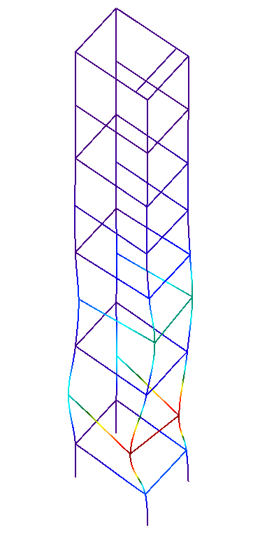
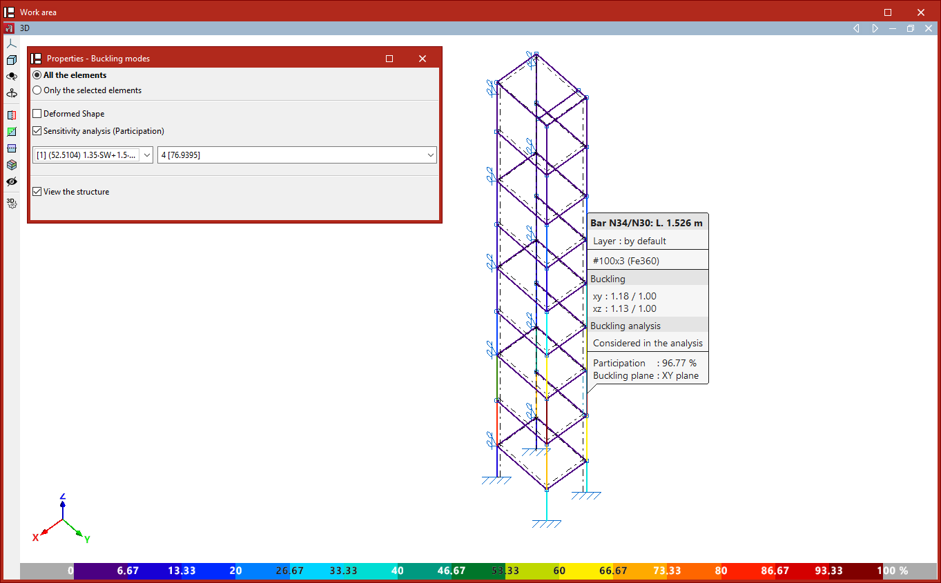
Lift structure
Much like the previous case, the aim here is to compare the structural performance of a lift before and after carrying out a buckling analysis. To do this:
- The lift structure shown is defined by applying a buckling coefficient of 1 to the bars, thereby ensuring compliance with the relevant standards.
- From this point onwards, the buckling analysis begins. Firstly, ensure that all bars of the structure shown are included in the buckling analysis.
- The buckling analysis is carried out.
- Once the analysis has been completed, you can view the deformed shape, the critical load factors obtained and the contribution factor for each bar in every loadcase and mode.
- Buckling coefficients in both planes are assigned to the bars in the structure.
- The new buckling coefficients analysed may compromise the validity of the checks carried out on the bars before the buckling analysis.
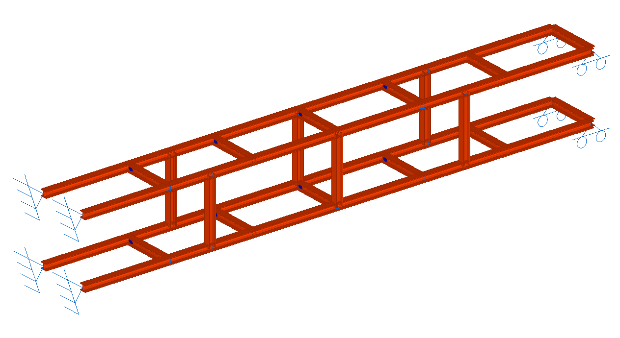
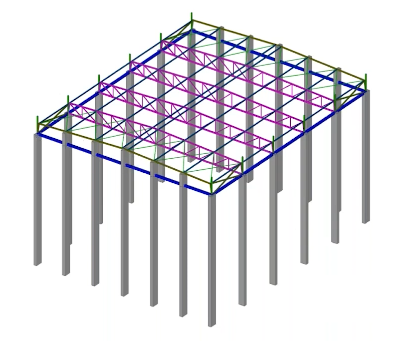
Industrial building with tall concrete columns
The objective is to determine and assign buckling coefficients for the concrete columns forming the side walls of an industrial building, which are of considerable height (over 30 metres). To this end:
- In this case, two analysis groups are defined: the group comprising the side columns and the group comprising the roof purlins. This ensures that the analysis of the elements in both groups is carried out independently, so that they do not interfere with one another. The remaining structural elements are not included in any other analysis group.
- The buckling analysis is carried out.
- Buckling coefficients in both planes are assigned to the columns.
- In any of the checks carried out on the columns (such as the check for the "Ultimate limit state under normal stresses"), the slenderness ratio obtained from the buckling coefficient analysed by the program is taken into account.
Buckling analysis groups
Linear buckling analysis groups can be created and edited using the "Analysis groups" option, which is available in the "Buckling" section of the top toolbar, within the "Analysis" tab (under the "Structure" tab).

The purpose of defining buckling analysis groups is to analyse the buckling behaviour of different sets of structural bars independently.
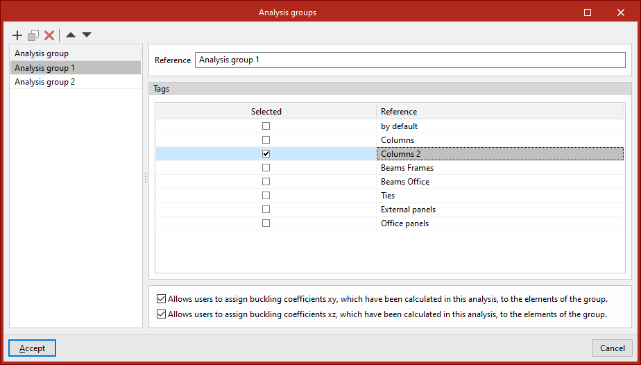
Analysis groups
A buckling analysis group defines a subset of model elements for which a buckling analysis will be performed, such that the buckling modes obtained involve only the elements in the group.
When clicking on this option, the program opens a window where you can add analysis groups to the list on the left-hand side. When adding a group, you must enter its "Reference". You must then specify the "Tags" of the elements you wish to include in the group by ticking the relevant boxes.
Finally, for each analysis group, selecting the following options at the bottom allows the buckling coefficients in each plane calculated in this analysis to be assigned to the elements in the group:
- Allows users to assign buckling coefficients xy, which have been calculated in this analysis, to the elements of the group (optional)
- Allows users to assign buckling coefficients xz, which have been calculated in this analysis, to the elements of the group(optional)
Defining buckling analysis groups is optional:
- If no groups are defined, the program will perform a single analysis taking into account all bars and shells in the model that are marked with the "Include in buckling analysis" option (under the "Properties" tab, in the "Bar" and/or "Shells" sections, "Buckling" option).
- If one or more buckling analysis groups are defined, the buckling analysis for each group will take into account all bars marked with the "Consider in buckling analysis" option and which also have one of the tags selected in the group definition assigned to them.
If a beam belongs to more than one group and its buckling coefficient is assigned automatically in the XY plane, the XZ plane, or both, it will be assigned the highest of all the coefficients calculated in the buckling analyses for the groups to which it belongs.
The buckling analysis results are displayed for the selected analysis group.
| Note: |
|---|
| Tags are defined and assigned in advance to the various elements of the structure via the "Tags" panel, which is located by default on the left-hand side of the main interface. |
Combinations for buckling analysis
Load combinations used in buckling analysis can be entered, generated and/or edited using the following option, which is available in the "Buckling" section of the top toolbar, within the "Analysis" tab (under the "Structure" tab).

Combinations
The structural stability must be analysed using load combinations. The "Combinations" option allows you to define the combinations you wish to analyse.
As with non-linear analysis, load combinations are defined based on the loadcases specified in the "General data" section for the structure.
Clicking on the option opens the "Buckling combinations" window.
The program allows you to define the combinations to be analysed in three ways:
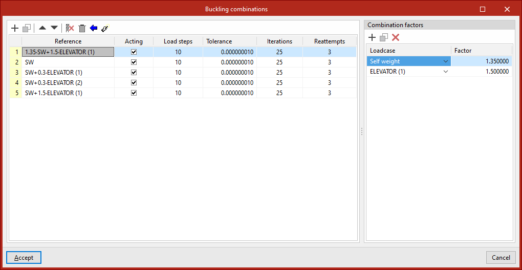
Entering combinations manually
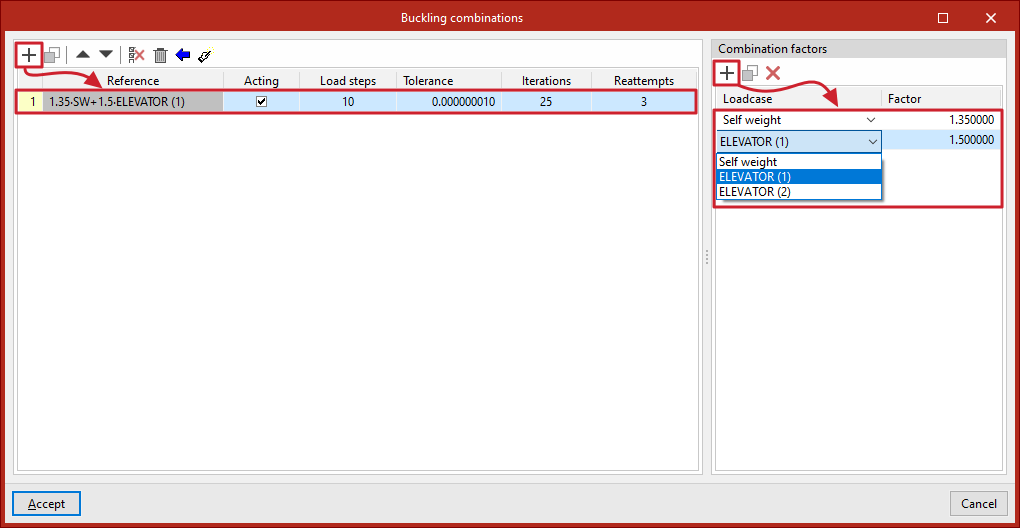
Load combinations for buckling analysis can be added manually to the list on the left-hand side using the options on the top toolbar.
Each combination is defined as follows:
- The "Reference" is generated automatically based on the loadcases and combination factors defined below
- You can indicate whether the combination is '"Acting" or not by ticking the box in the next column
- and the number of "Load steps", the "Tolerance" value, the number of "Iterations" used in the analysis, and the number of "Reattempts" are defined.
Next, on the right-hand side, for each combination entered in the list, the "Combination factors" are defined by entering the value of the "Factor" for each "Loadcase" of the model selected from the drop-down menu.
Generating combinations based on the loadcases defined in the project
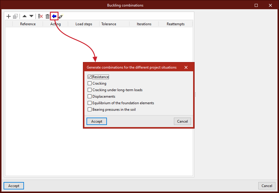
It is possible to define combinations for the buckling analysis by automatically generating all possible combinations based on the conditions defined in the project.
To do this, click the "Generate combinations for the different project situations" button at the top of the list of combinations. In the pop-up window, select the project loadcases from which you wish to retrieve the information, which include the following:
- Resistance (optional)
- Cracking (optional)
- Cracking under long-term loads (optional)
- Displacements (optional)
- Equilibrium of the foundation elements (optional)
- Bearing pressures in the soil (optional)
To apply the settings, click "Accept". The program will generate all combinations of the selected loadcases, automatically adding the necessary entries to the list and the corresponding combination factors.
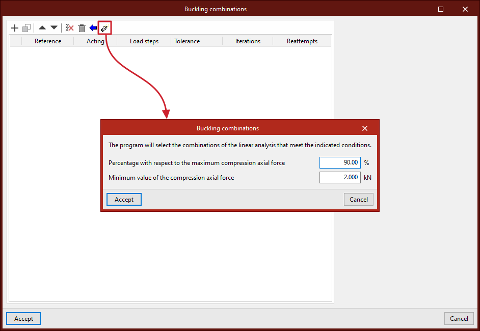
Generating combinations based on the results of the linear analysis
If the structure has been analysed, you can use the "Generate combinations from the results of the linear analysis" option at the top of the combination list. This option automatically adds to the list those combinations in which the largest axial compression forces occur in the structural bars, depending on the conditions defined by the user in the pop-up window.
The program will therefore filter the structural combinations and add to the list those that contain compressed bars with axial forces greater than the "Percentage with respect to the maximum compressive axial force" found in other combinations, and with a "Minimum value of the compressive axial force" expressed in the defined units of force.
To apply the settings, click "Accept". Of all the combinations generated based on the defined loadcases, the program will retain those that meet these requirements, adding the entries to the list along with the corresponding combination factors for each loadcase.
Buckling analysis: "Analysis" option
The buckling analysis is configured and run using the following option, available in the "Buckling" section of the top toolbar, within the "Analysis" tab (under the "Structure" tab).

Analysis
The "Analysis" option allows you to perform a buckling analysis. The window that appears when you click this option allows you to configure the following parameters.
These parameters must be entered for each buckling analysis group, if any have been defined. The analysis groups will appear on the left-hand side of the window. The program will perform the analysis for the groups where the "Analysis" box is ticked.
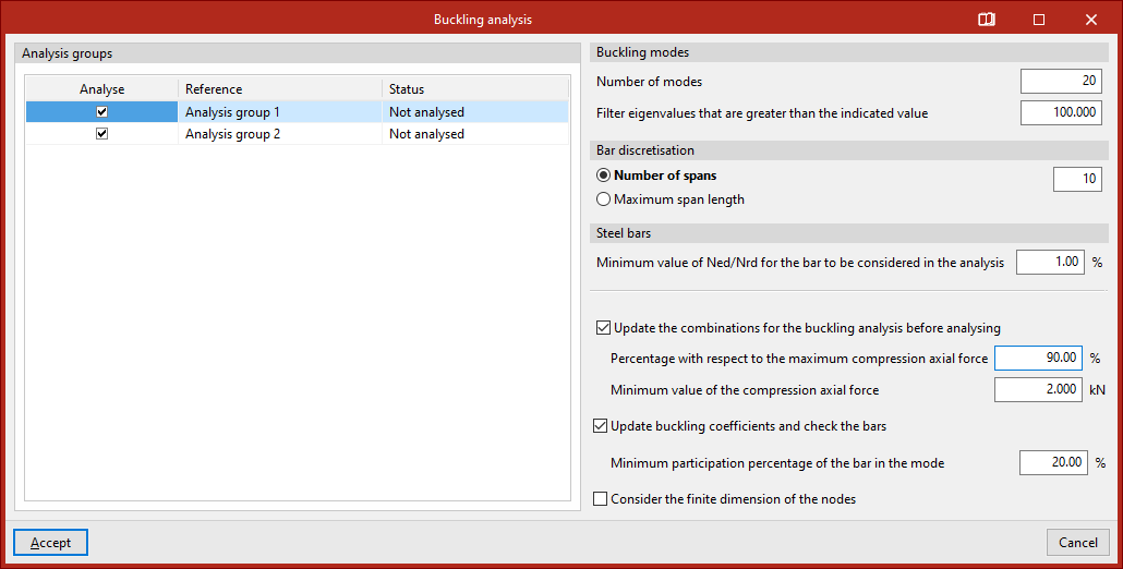
- Firstly, you can specify the number of "Buckling modes" to be analysed. If you select "Filter eigenvalues that are greater than the indicated value", modes in which the critical load factor is very high will not be displayed.
- "Bar discretisation" is also set, either by "Number of spans" or by "Maximum span length".
- Next, for "Steel bars", you can also apply a filter for bars with small compression axes by specifying the "Minimum Ned/Nrd value for a bar to be considered in the analysis". The program will not include bars with a compression axis smaller than the percentage specified in this section.
- If the structural analysis has been performed, the program displays a series of additional options for "Update the combinations for the buckling analysis before analysing", specifying the "Percentage with respect to the maximum compression axial force" and the "Minimum value of the compression axial force". This way, these combinations will be generated directly for the buckling analysis, without the need to do so beforehand via the "Combinations" option in the group.
- The program also allows you to "Update buckling coefficients and check the bars" as part of the same analysis process. To do this, you specify the "Minimum participation percentage of the bar in the mode" so that its buckling coefficient is updated. This means you will not need to use the "Assign coefficients" option in the same group.
- Finally, you can "Consider the finite dimension of the nodes" by selecting the last option.
Clicking "Accept" starts the buckling analysis.
Once completed, the program will display an "Information" message, which you must click "Accept" to confirm.
View results by buckling mode
The results obtained by mode in the linear buckling analysis can be viewed using the following option, available in the "Buckling" section of the top toolbar, within the "Analysis" tab (under the "Structure" tab).

Buckling modes
The "Buckling Modes" option allows you to view on screen the results obtained from the linear buckling analysis for the different buckling modes considered for each load combination.
In the "Properties - Buckling Modes" window that appears, you can choose to display "All elements" or "Only the selected elements".
You can then choose to display the "Deformed shape" view by entering a scaling factor for the deformation. Next to this, the button allows you to view an "Animation" of the selected buckling mode.
Use the drop-down menus below to select the load combination and buckling mode you wish to view:
- In the load combination selection drop-down menu, the mode number is shown in square brackets, and the critical load factor for that mode is shown in round brackets. The mode with the lowest factor in the list of modes is displayed.
- The buckling mode selection drop-down menu displays the mode number and, in brackets, its critical load factor.
The program can determine the buckling coefficients in each plane using the calculated values of the critical load factors obtained from the buckling analysis, and assign them to the bars by selecting the relevant option.
The calculated buckling coefficients are displayed in an information box that appears when you hover the cursor over the bars.
| Note: |
|---|
| The critical load axis (Ncr) is obtained by multiplying the critical load factor (αcr) of the buckling mode by the load-bearing axis of that load combination (Ned): Ncr = Ned * αcr Using Euler’s critical load formula, the buckling beta coefficient (β) for each member can be determined: Ncr = π²*EI / (βL)² β = (π/L)*(EI/(Ned * αcr))¹/² |
Sensitivity analysis
The program can carry out a sensitivity analysis based on the deformation energy, thereby determining whether each buckling mode affects or is relevant to each bar.
Ticking the "Sensitivity analysis" box displays the percentage contribution of each bar to the total using a colour-coded scale.
The bar that is most filled in will show a percentage of 100%. The other bars will show a percentage between 0 and 100%.
| Note: |
|---|
| If a bar has a very low percentage of participation in a given combination and mode, the bar will not sway, or will sway only very slightly. |
Checking buckling contour plots
Isovalues for buckling analysis can be viewed using the following option, available in the "Buckling" section of the top toolbar, within the "Analysis" tab (under the "Structure" tab).

Contour plots
The program enables the analysis of buckling in shells.
Using the "Buckling" option in the "Shells" section of the "Properties" tab, you can select the sheets to be included in the linear buckling analysis.
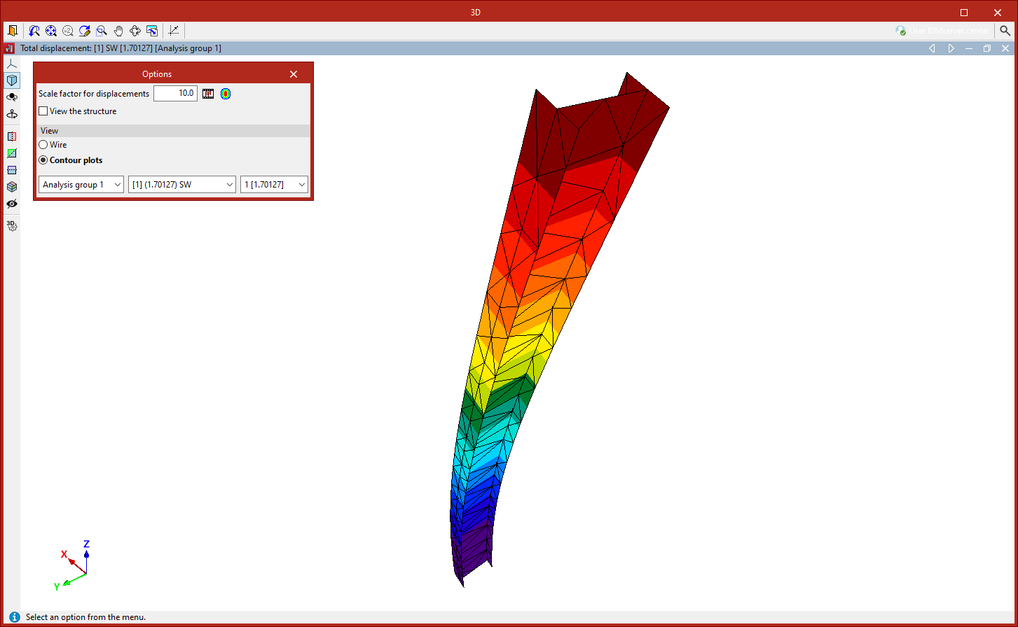
Once the buckling analysis has been carried out, the "Contour plots" option in the "Analysis" tab allows you to view the contour plots of the deflection for the different buckling modes in a pop-up window.
A pop-up dialogue box appears in this window to configure various "Options":
- Firstly, you can adjust the "Scale factor for displacements" and the "Colours for the representation of contour maps", as well as view an "Animation" of the deformed shape.
- The "View structure" option allows you to display the original geometry of the structure on screen.
- You can select the "Display" option in "Wire" mode, which shows only the outlines of the mesh elements, or "Contour plots" mode, which colours the elements in full.
- Use the drop-down menus at the bottom to select the analysis group, load combination and vibration mode you wish to view. The value of the calculated critical load factor is shown in brackets.
Assigning buckling coefficients
Buckling coefficients can be assigned either during the analysis or using the following option, available in the "Buckling" section of the top toolbar, within the "Analysis" tab (under the "Structure" tab).

Assignment of buckling coefficients
The program automatically calculates the buckling coefficients for each bar included in the buckling analysis based on the critical load factors and the stressed axis.
The coefficients obtained can be allocated in two ways:
- In the same buckling analysis process launched using the "Analysis" option, by selecting the "Update buckling coefficients and check the bars" option,
- Or by using the "Assign buckling coefficients" option in the "Buckling" group at a later stage of the analysis.
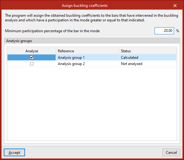
The sensitivity analysis allows us to determine which buckling modes affect each bar, to calculate and assign buckling coefficients. To this end, in either of the two cases described above, the "Minimum participation percentage of the bar in the mode" is specified so that its buckling coefficient can be updated.
The program will assign the buckling coefficients obtained to the bars that were included in the buckling analysis and that have a contribution to the dominant mode equal to or greater than the specified value.
| Note: |
|---|
| If a bar's buckling percentage exceeds the specified value, the bar is considered to be buckling in that buckling mode, and its associated critical load factor should therefore be used. Using the list of axes and the critical load factors for each member under each load combination, it is possible to determine the highest buckling coefficient for each plane. |
At the bottom of the window that appears when you click on "Assign buckling coefficients", the program allows you to select one or more of the "Analysis groups" for which the analysis has been performed. The program will assign to each bar the highest of all the coefficients calculated in the buckling analyses of the groups to which it belongs.
Clicking "Accept" applies the buckling coefficients.
Defining load cases for modal analysis
Loadcases for modal vibration analysis can be entered and edited using the following option, which is available in the "Modal" section of the top toolbar, within the "Analysis" tab (under the "Structure" tab).

Loadcases
The "Loadcases" option allows you to define the load cases for the modal analysis.
Clicking this opens the "Loadcases for modal analysis" window. These load cases must be added to the list on the left using the options on the top toolbar. Each case is defined as follows:
- The "Reference" is generated automatically based on the loadcases and combination factors defined below;
- Indicate whether the case is "Active" or not by ticking the relevant box;
- The number of "Load steps", the "Tolerance" value, the number of "Iterations" used in the analysis, and the number of "Reattempts" are defined.
Next, on the right-hand side, for each loadcase entered in the list, you must define the following:
- The "Overall direction of mass to be considered" is specified as follows:
- "Translational X and Y and rotational Z"
- and/or "Translational Z and rotational X and Y";
- At the bottom, the "Combination factors" are defined by entering the value for the "Factor" for each "Loadcase" of the model selected from the drop-down menu.
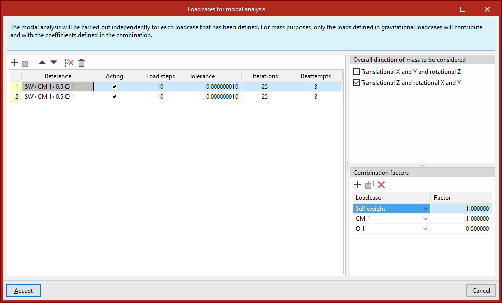
| Note: |
|---|
| Modal vibration analysis is performed separately for each of the load cases defined in this dialogue box. For mass purposes, only the loads defined in gravity load cases will be taken into account, and they will be applied using the coefficients defined in the combination. |
Modal analysis: "Analysis" option
The modal vibration analysis is configured and run using the following option, available in the "Modal" section of the top toolbar, within the "Analysis" tab (under the "Structure" tab).

Analysis
The "Analysis" option allows you to run the modal analysis.
To do this, the combinations for the modal analysis must have been defined using the previous option in the group.
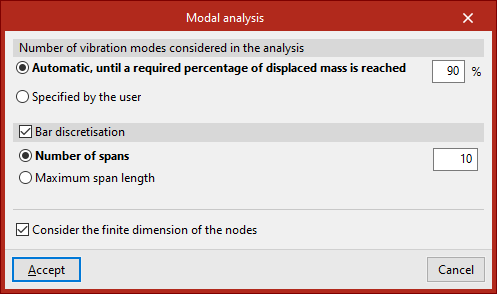
Clicking on this option opens the "Modal analysis" window, which allows you to configure the following options:
- The "Number of vibration modes considered in the analysis", which can be:
- "Automatic, until a required percentage of the mass has been displaced",
- or "User-specified".
- The program also allows you to enable "Bar discretisation" by ticking the relevant box. This can be defined as follows:
- specifying a "Number of sections",
- or by entering the value for "Maximum section length".
- Finally, you can "Take into account the finite dimension of the nodes" by selecting the last option.
The results of the modal analysis can be viewed using the two options in this section, "Vibration modes" and "Report", which will become available once this analysis has been completed.
Display of modal analysis results by vibration mode
The results of the modal vibration analysis can be displayed on screen using the following option, which is available in the "Modal" section of the top toolbar, within the "Analysis" tab (under the "Structure" tab).

Vibration modes
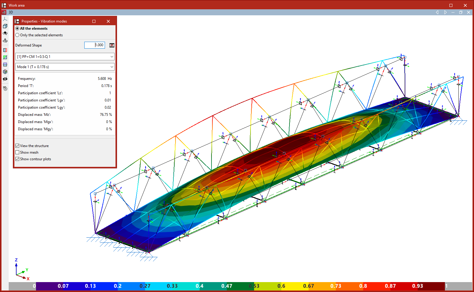
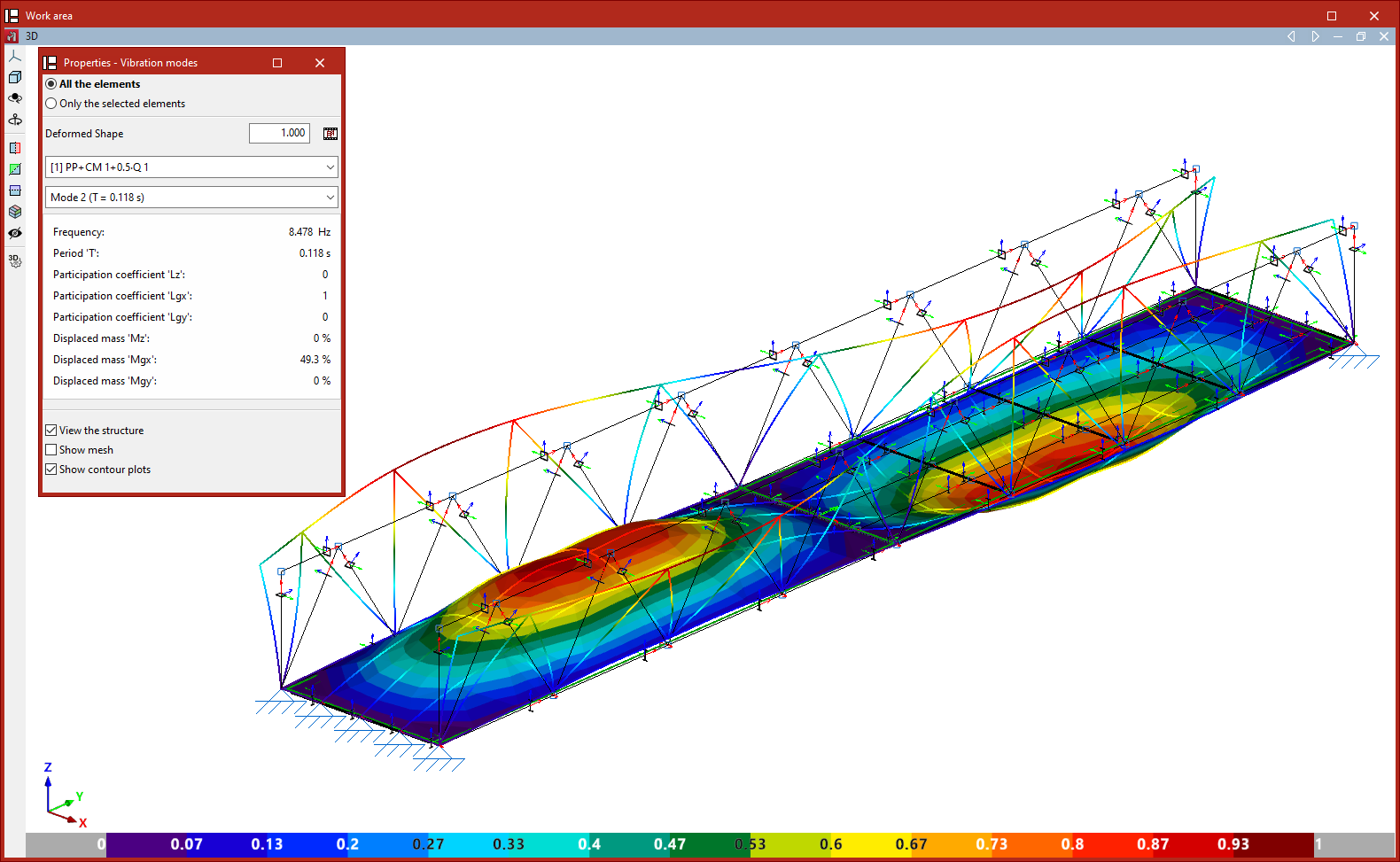
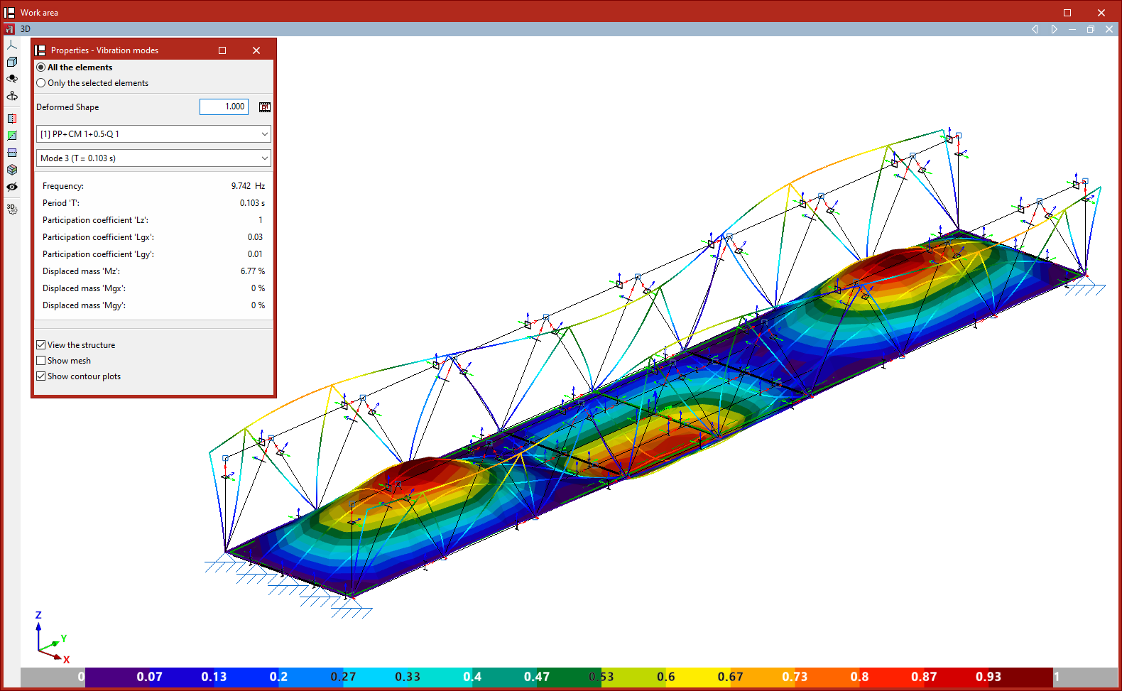
Once the analysis has been carried out, the "Vibration modes" option allows you to view the results of the modal analysis graphically on screen for each defined loadcase and each vibration mode, including animations.
In the "Properties - Vibration modes" window that appears, you can configure how the results are displayed.
First, you must specify whether you wish to view "All the elements" or "Only the selected elements"; in the latter case, you must select the elements in the template by clicking on them with the left mouse button.
Next, a factor is defined for the "Deformed shape" view. Next to this, the button allows you to view an "Animation" of the selected loadcase and vibration mode.
The following two drop-down menus allow you to select the loadcase and vibration mode you wish to view.
The table below shows the values obtained when analysing various parameters for the selected loadcase and vibration mode, such as:
- the frequency,
- the period,
- the participation coefficients in the analysis directions,
- and the percentages of displaced mass in the directions of analysis.
Finally, the "View structure" option allows you to overlay the structure view in the workspace alongside the deformed view.
If the model includes shells, the "Show mesh" and "Show contour plots" checkboxes also appear, allowing you to visualise the mesh elements and display the analysed contour plots using a colour gradient.
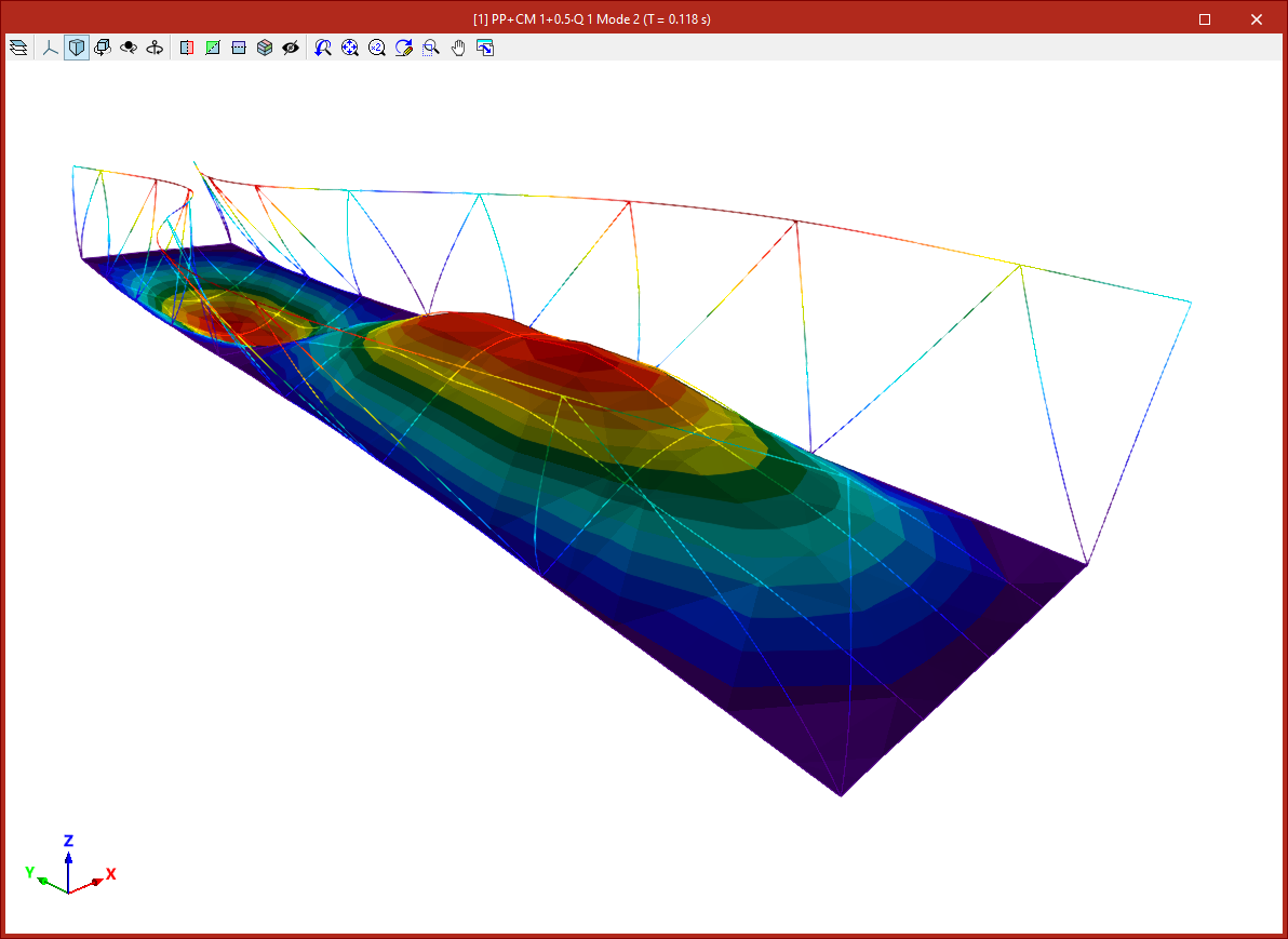
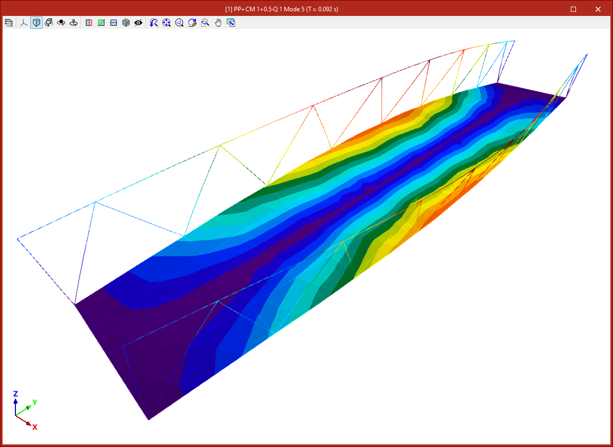
Animations
Obtaining the modal analysis report
The list of results from the modal vibration analysis can be obtained using the following option, available in the "Modal" section of the top toolbar, within the "Analysis" tab (under the "Structure" tab).

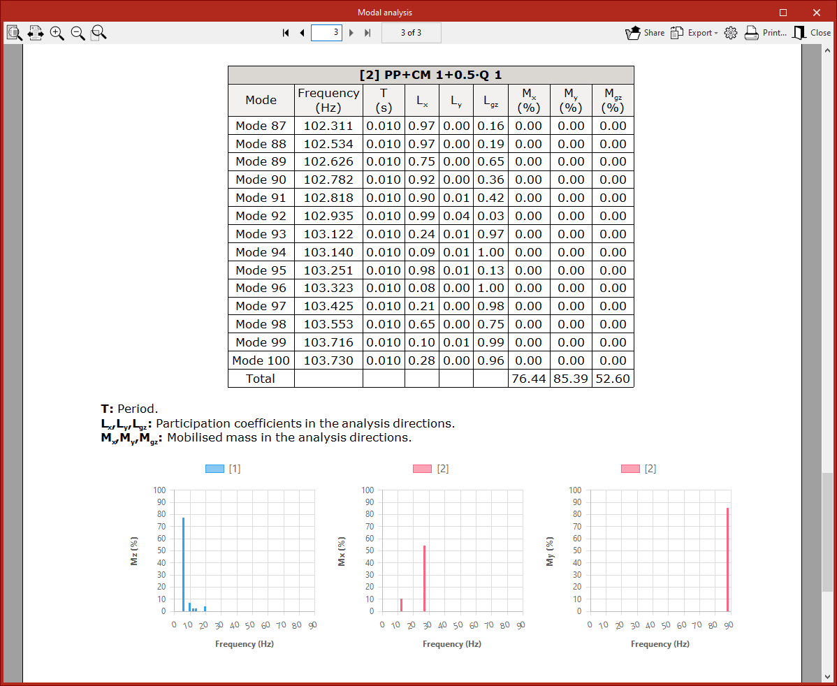
Modal analysis report
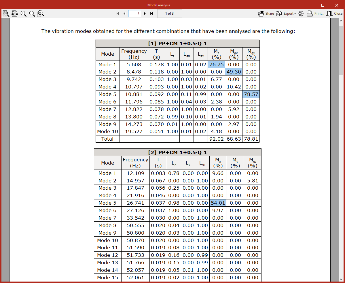
The results can be generated as a "Report" after performing the modal analysis using this option.
The following values are shown in a table below for each vibration mode:
- "Frequency",
- the period ("T"),
- the contribution coefficients in the directions of analysis (Lx, Ly, Lz, Lgx, Lgy, Lgz),
- and the percentages of mass displaced in the analysis directions (Mx, My, Mz, Mgx, Mgy, Mgz).
The final row shows the percentages of total tonnage corresponding to the sum of the percentages by mode.
In this list, the most significant percentages of mobilised mass are highlighted in blue for easy identification. This makes it possible to check more efficiently whether the structure’s dynamic behaviour falls within the generally accepted safety and comfort thresholds.
Viewing and checking issues, warnings and errors
Show/Hide issues
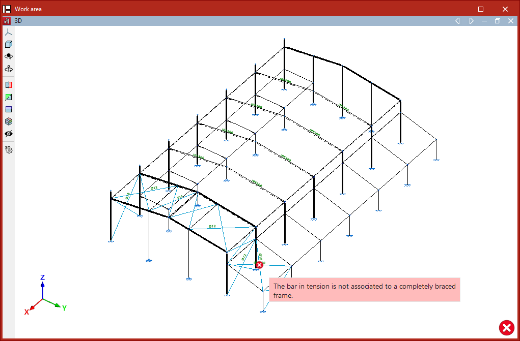
The "Issues" option, located within the "Analysis" tab on the "Structure" or "Foundation" panel, allows the program to display the position of issues in the model graphically. If you hover the mouse cursor over each one, a message describing the problem is displayed.

Below are some of the issues that may arise in the program. Click on any of the links provided to find a detailed explanation of each problem and recommendations for resolving it:
- One of the elements of the continuous beam forms an angle greater than 80 with the horizontal plane.
- The column cannot form part of a braced frame.
- The braced frame has not been completely introduced.
- The bar in tension is not associated to a completely braced frame.
- The length of the bar is less than the minimum permitted length.
- The element must be vertical, with its local x axis in the ascending direction.
- The element is not defined between two levels.
- The beam cannot form part of a braced frame.
- The sections used for the two braces that make up a braced frame must be identical.
- A node has been found that is not connected to a bar or a shell.
- A tie cannot have intermediate nodes.
Warnings and errors when checking elements
Other errors and warnings that the program may display on screen after the analysis, when using the "Check elements" or "U.L.S. checks" options in the top toolbar of the "Analysis" tab, are as follows:
- The compression axial force is excessive and exceeds the critical buckling axial forces.
- The compression axial force is excessive and exceeds the critical buckling axial forces.
- The tensile axial force is excessive and exceeds the plastic resistant axial force.
- It is not possible to carry out the check as the shear force is excessive and causes the section to fail. Therefore, it is not possible to check the interaction between bending and shear.
- An error has occurred; the slenderness of the bar is greater than the limit slenderness.
- It has been selected not to carry out the fire resistance check.
| Note: |
|---|
| Once the analysis process is complete, the program also displays any issues and errors that occurred during the process in the "Final design report". |
Table of contents
Complete your CYPE 3D journey by exploring the other available sections:
- Introduction
- Start: creating new projects, workflows, and examples
- Setting the work environment
- Setting the job data
- Defining the structure’s geometry
- Editing the properties of structural elements
- Entering and editing loads on the structure
- Designing and analysing connections
- Analyses, checks, and results
- Defining and editing reinforcement
- Designing and analysing foundation
- Printing documents and exporting data