Examples of buckling analysis in structures
Below are several examples of structures where the buckling analysis performed by the program can be applied, along with the sequence of steps for defining, analysing and viewing the results:
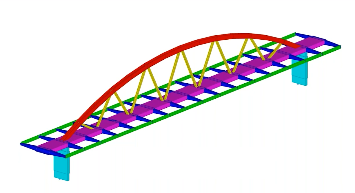
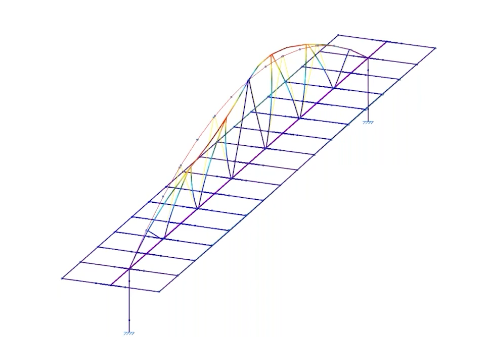
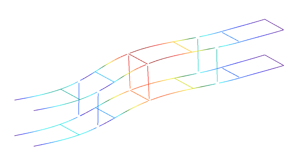
Arched steel walkway with a compressed top chord
The objective is to obtain and assign the buckling coefficients for the bars forming the compressed upper chord of the arch in a steel footbridge. This involves the following:
- The buckling analysis takes into account both the top chord bars and the lattice bars that brace them.
- The buckling analysis is carried out.
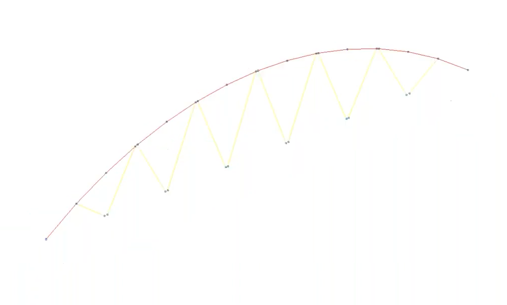
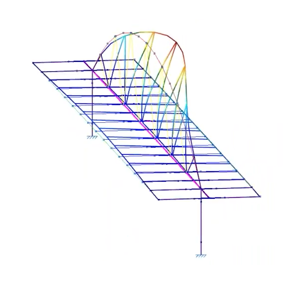
- Once the analysis has been completed, the deformation can be viewed for the various load combinations and buckling modes, along with the critical load factors obtained. Furthermore, a sensitivity analysis can be used to examine the participation coefficient of the bars in each combination and each mode. In this case, we can see that the bars in the upper chord account for the largest proportion; consequently, they are buckling.
- Buckling coefficients in both planes are assigned to the upper chord bars.
- In any of the checks carried out (such as the "Compressive strength" or "Slenderness limit" checks), the analysed buckling coefficient is taken into account.
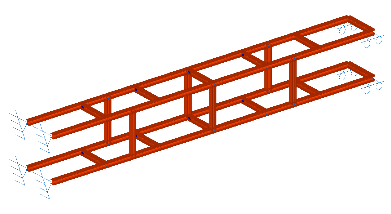
Strut between two retaining walls
The structure of this strut is subjected to compressive forces due to its position between two retaining walls.
The aim is to compare the structural performance of the components before and after carrying out the buckling analysis. To this end:
- The structure of the strut shown is defined by applying a buckling coefficient of 1 to the bars, thereby ensuring compliance with the regulations.
- From this point onwards, the buckling analysis begins. Firstly, ensure that all bars of the structure shown are included in the buckling analysis.
- The buckling analysis is carried out.
- Once the analysis has been completed, you can view the deformation, the critical load factors obtained and the contribution factor for each bar in every loadcase and mode.
- Buckling coefficients in both planes are assigned to the structural bars.
- The new buckling coefficients analysed may compromise the validity of the checks carried out on the bars before the buckling analysis.
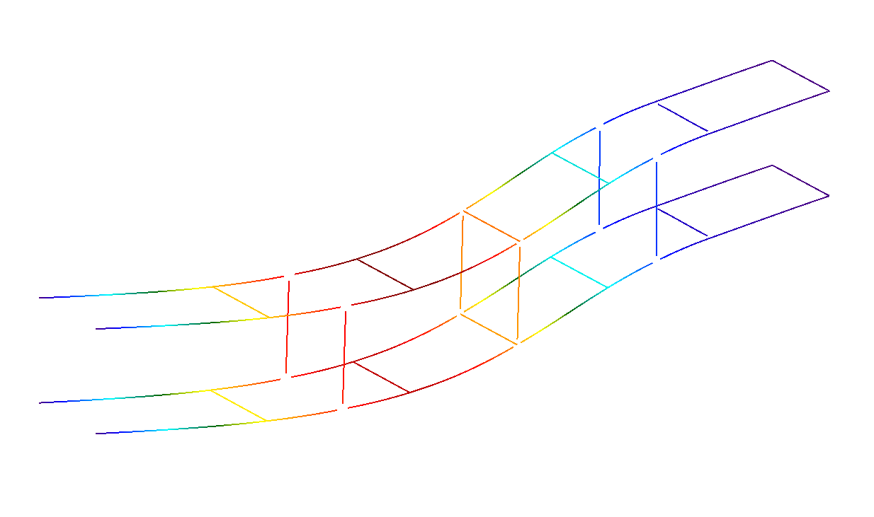
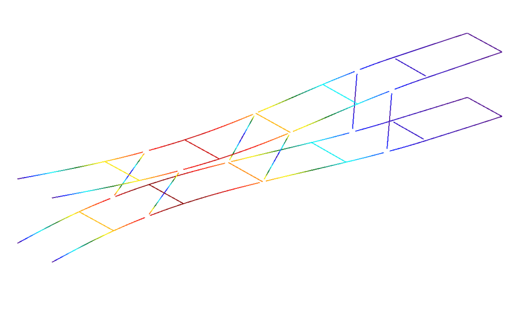
Buckling modes
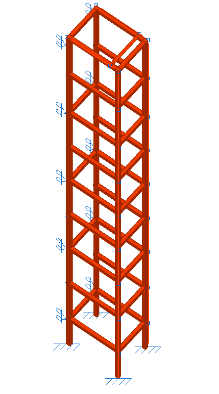
Lift structure
Much like the previous case, the aim here is to compare the structural performance of a lift before and after carrying out a buckling analysis. To do this:
- The lift structure shown is defined by applying a buckling coefficient of 1 to the bars, thereby ensuring compliance with the relevant standards.
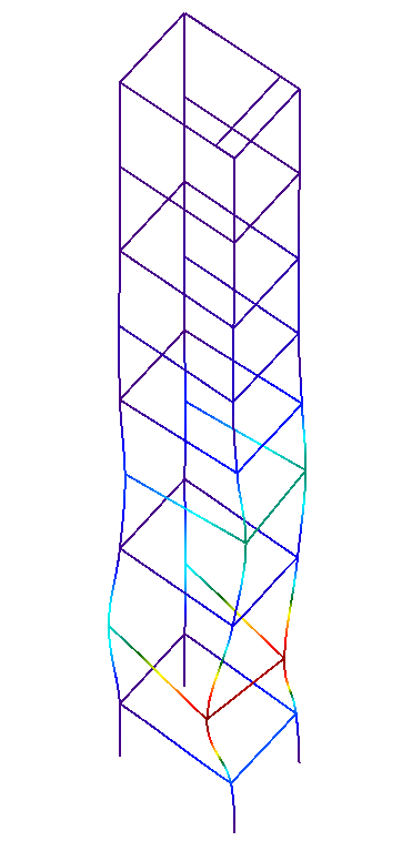
- From this point onwards, the buckling analysis begins. Firstly, ensure that all bars of the structure shown are included in the buckling analysis.
- The buckling analysis is carried out.
- Once the analysis has been completed, you can view the deformed shape, the critical load factors obtained and the contribution factor for each bar in every loadcase and mode.
- Buckling coefficients in both planes are assigned to the bars in the structure.
- The new buckling coefficients analysed may compromise the validity of the checks carried out on the bars before the buckling analysis.
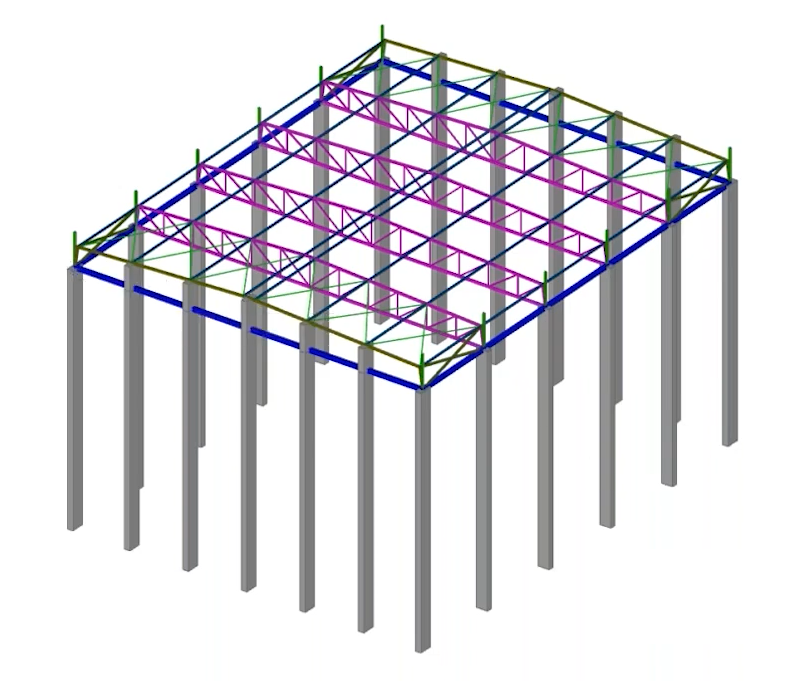
Industrial building with tall concrete columns
The objective is to determine and assign buckling coefficients for the concrete columns forming the side walls of an industrial building, which are of considerable height (over 30 metres). To this end:
- In this case, two analysis groups are defined: the group comprising the side columns and the group comprising the roof purlins. This ensures that the analysis of the elements in both groups is carried out independently, so that they do not interfere with one another. The remaining structural elements are not included in any other analysis group.
- The buckling analysis is carried out.
- Buckling coefficients in both planes are assigned to the columns.
- In any of the checks carried out on the columns (such as the check for the "Ultimate limit state under normal stresses"), the slenderness ratio obtained from the buckling coefficient analysed by the program is taken into account.