
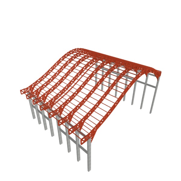
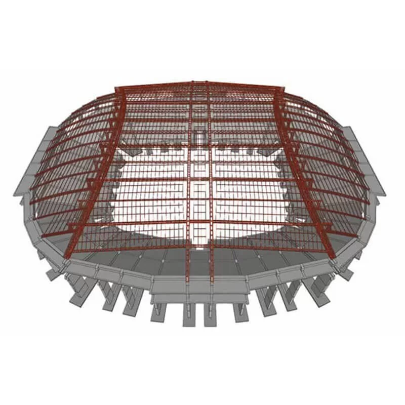
Examples of structures designed in CYPE 3D
CYPE 3D is a program specialising in the design and structural analysis of 3D free-form structures. This enables the design of various types of structures, such as the following:
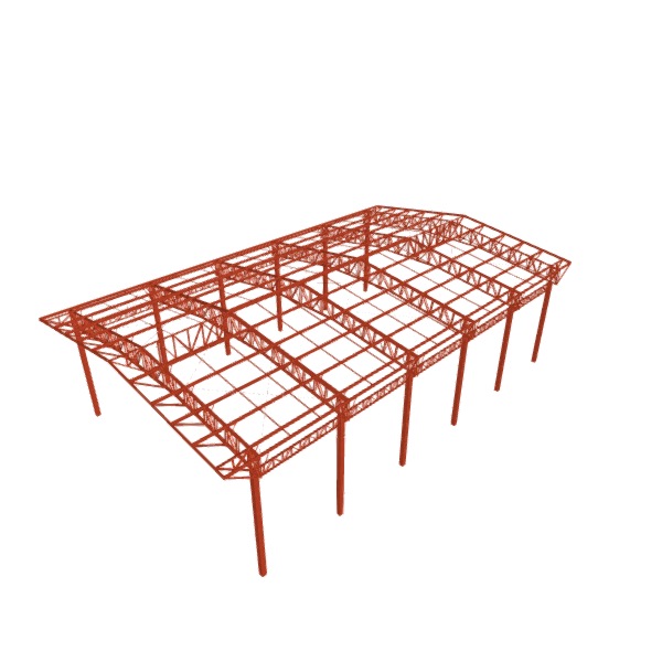
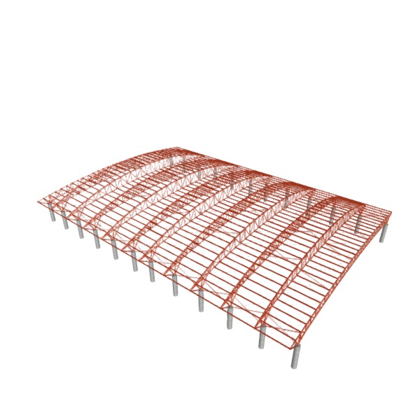
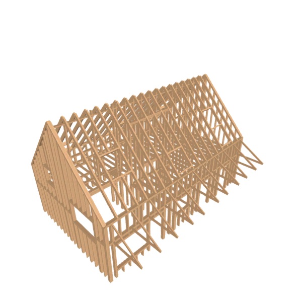
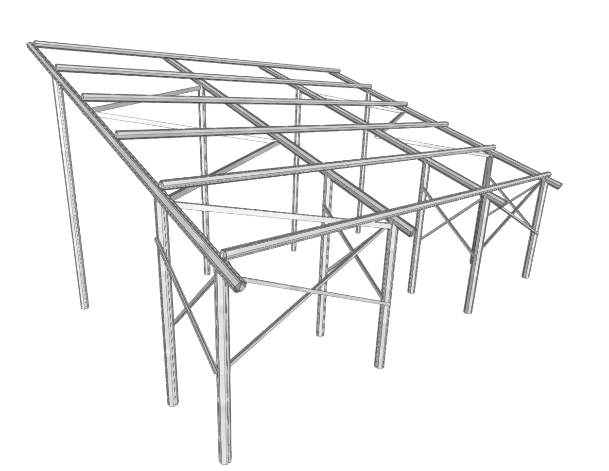
- Industrial buildings (structures with portal frames or trusses)
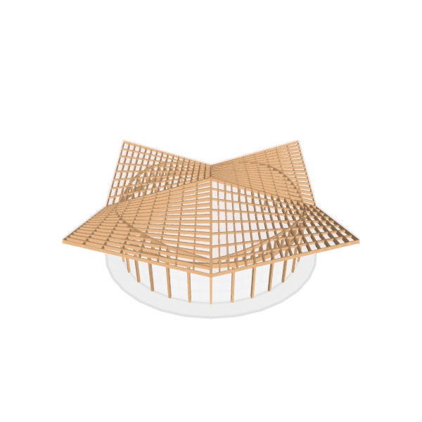
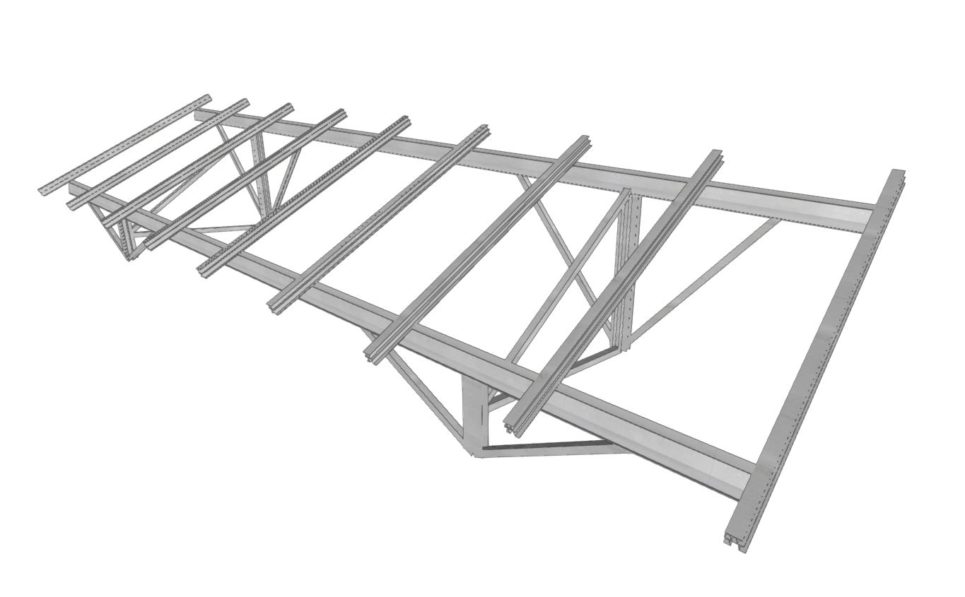
- Canopies and lightweight roofing
- Footbridges and pedestrian bridges
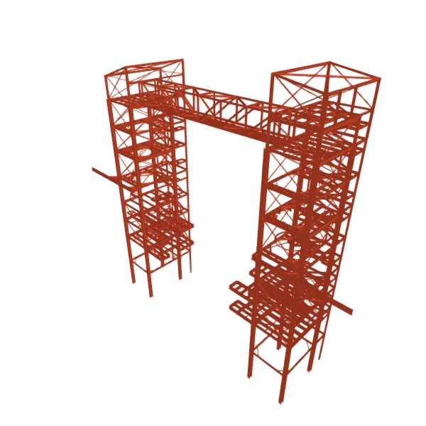
- Support structures for machinery or equipment
- Electricity pylons or signposts
- Industrial storage racking
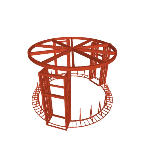
- Silos, tanks and storage tanks
- Auxiliary, temporary or supporting structures on site
- Structural reinforcements and extensions to buildings (cantilevers, roofs, façade support structures, etc.)
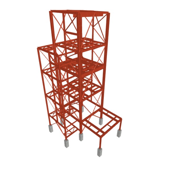
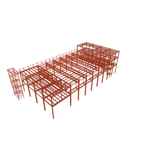
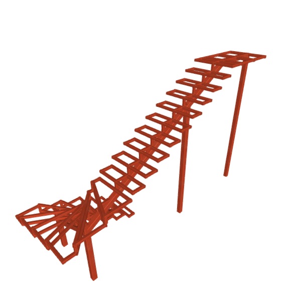
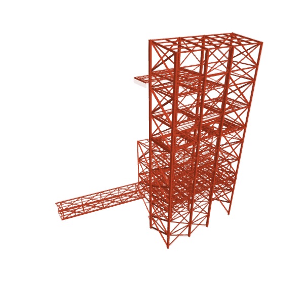
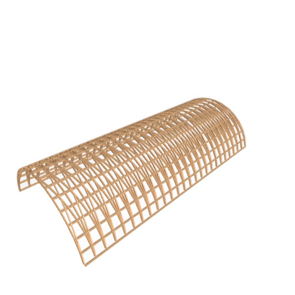
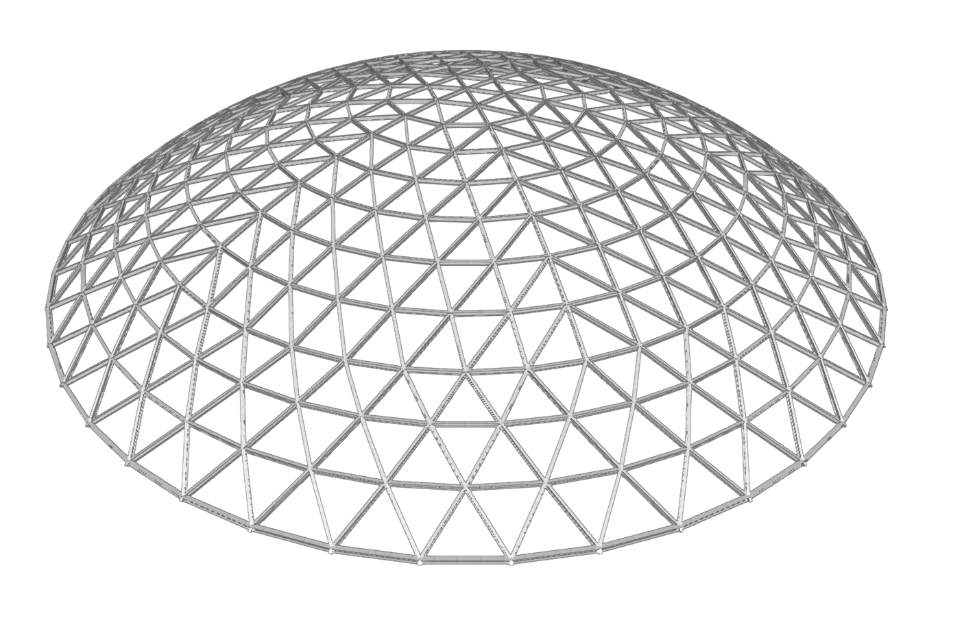
Below are some examples of structural models developed using the program:
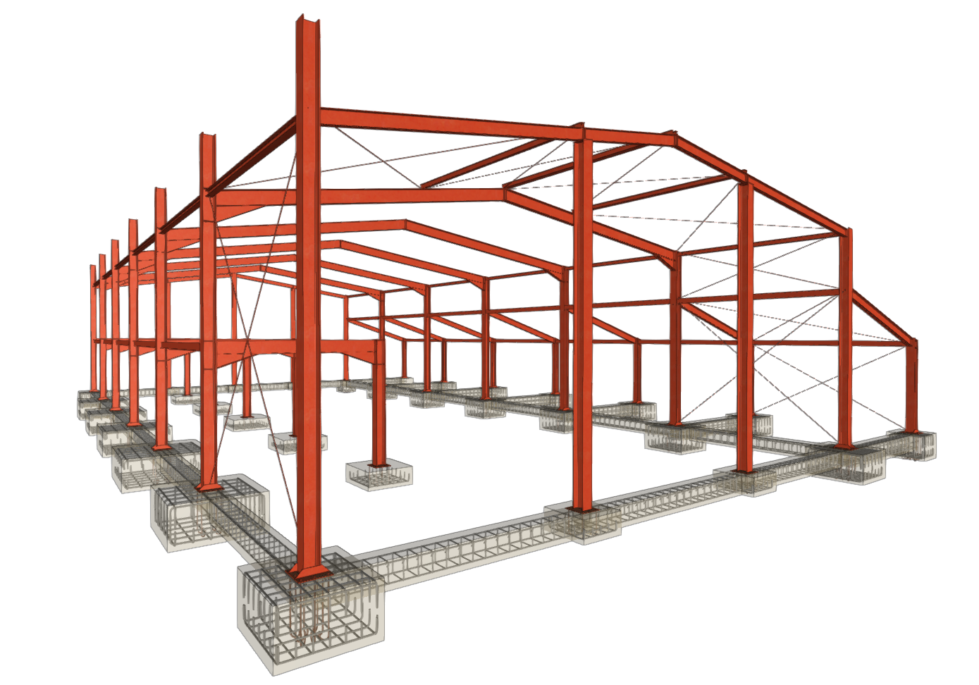
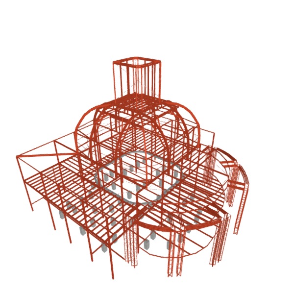
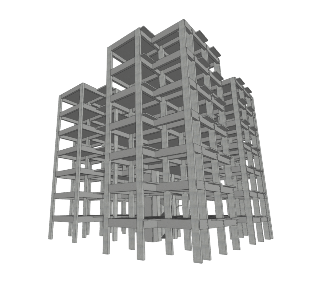
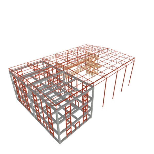
Steel structures
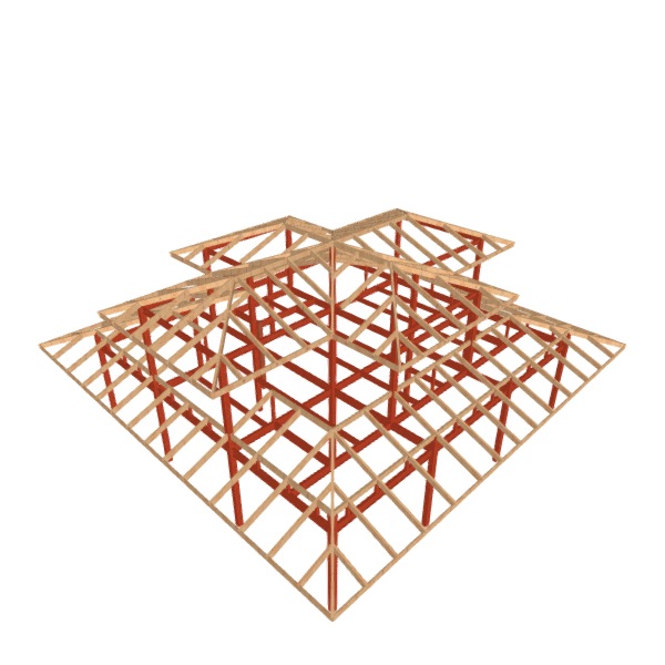
Timber structures
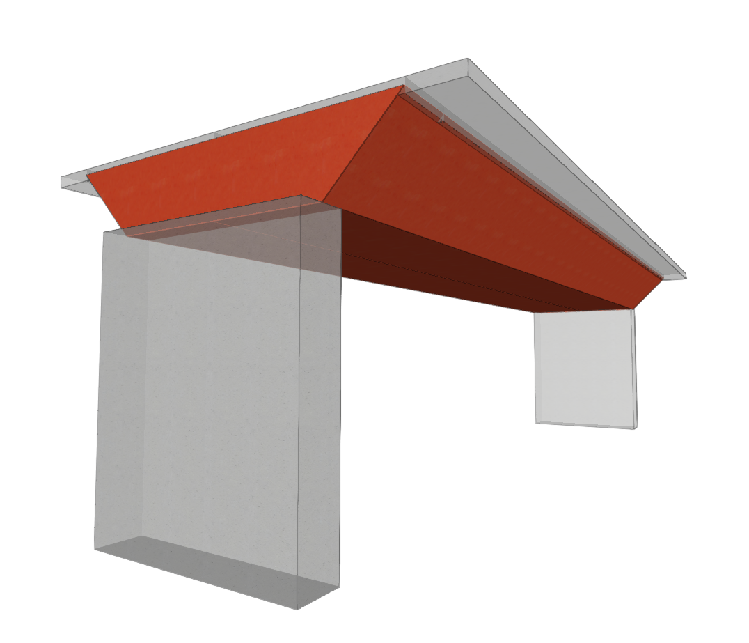
Aluminium structures
Concrete and composite structures
| Note: |
|---|
| Please follow this link to view the CYPE 3D contributions gallery on the BIMserver.center platform. |
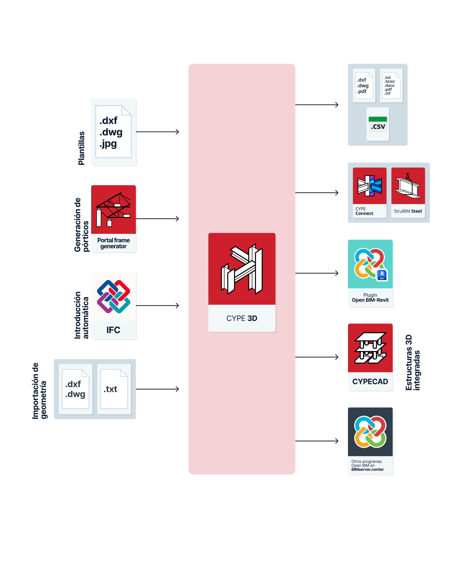
Workflows supported by the program
CYPE 3D is a tool that offers different workflow options:
Data entry
Free modelling/modelling with templates
CYPE 3D can be used for either free or template modelling of the structure, either from scratch (as an "Empty job") or to complete the definition of imported data in other workflows:
- Modelling the structure by direct input into CYPE 3D.
- Modelling the structure in CYPECAD based on DXF-DWG, DWF, PDF templates or images (.jpeg, .jpg, .bmp, .wmf, .emf, .pcx).g, .jpg, .bmp, .wmf, .emf, .pcx).
Importing models with Portal frame generator
Portal frame generator can be used to automatically generate the geometry and loads of a parallel portal frame structure and export the data to CYPE 3D, where the complete model analysis will be carried out.
If you start by using Portal frame generator, you can carry out the following actions:
- Generating the CYPE 3D model from the data entered in the Portal frame generator. The information generated includes the following:
- The bar geometry of the indicated portal frame or the complete portal frame system.
- The necessary load cases
- If applicable, the necessary load panels that carry out the distribution of surface loads and that incorporate the information of the self-weight of the envelopes and purlins, and/or of the live load on the roof.
- The wind and snow surface loads.
- The grouping of frames.
- The lengths or buckling coefficients of the portal frame bars.
- The supports or external connections of the columns.
Automatic entry from IFC files
When starting a new project, CYPE 3D offers a specific option for automatic data entry and generation of data contained in IFC files:
- Automatic data entry from the import of structural analysis models from IFC files. The entities that CYPE 3D is capable of importing from IFC files are the following:
- Node import (IFCStructuralPointConnection), with their external connection conditions.
- Bar import (IFCStructuralCurveMember), with their end fixity conditions and descriptions.
Other automatic generation options
As well as those mentioned above, CYPE 3D can automatically generate the geometry of the structure by importing data from the following files:
- Automatic geometry generation from DXF or DWG files. The lines represented in these files will be transformed into bars in CYPE 3D.
- Automatic geometry generation from text files with a given format.
Data output
Data export from CYPE 3D
- Exporting reports to HTML, DOCX, PDF, RTF and TXT formats.
- Exporting drawings to DXF, DWG and PDF formats.
- Export to CSV format files with data such as the geometry of nodes or forces by loadcase, combinations and envelopes of the bars.
- Export of the information contained in CYPE 3D to the BIMserver.center platform using IFC and GLTF formats, ensuring interoperability and the efficient exchange of information between different programs. This is so that it can be viewed by authorised project participants. The information generated by CYPE 3D can be used by the following programs:
- CYPE Connect
Import CYPE 3D steel structure sections and forces to carry out the detailed analysis of connections. - Autodesk Revit (via the Open BIM - Revit Plugin)
- Imports the information generated by CYPE 3D for visualisation and management in Revit. This includes elements such as bolts, welds, gussets and other connection components. Optionally, it is possible to generate native Revit elements from some elements of the structural IFC (such as bars, columns, beams and braces).
- CYPE Connect
Integrated 3D structures
Models developed in CYPE 3D and saved in .ed3 files can be incorporated into CYPECAD as integrated 3D structures.
This is used to carry out the analysis together with the rest of the elements entered in CYPECAD and, from this program, to export the data to Arquimedes. CYPECAD can export the bill of quantities to Arquimedes or to a file in FIEBDC-3 format so that it can be processed by other quantity surveying programs. This can include CYPE 3D model data after incorporation as integrated 3D structures.
Basic data input and output sequence for structural design and analysis in CYPE 3D
The design and analysis of structures in the program can be carried out using the following basic input and output sequence:
- Creating a new job (from "File", "New").
- Setting the general data (from the "Works" tab, "General data"), including the definition of standards, materials and loadcases.
- Entering and describing the geometry of the structure ("Geometry" tab):
- Entering nodes (options in the "Nodes" group).
- Entering bars (options in the "Bars" group).
- Entering shells (options in the "Sheets" group).
- Editing the properties of the elements in the structure ("Properties" tab):
- Editing node properties (options in the "Nodes" group), including the definition of internal and external connections.
- Editing bar properties (options in the "Bars" group), including buckling and lateral torsional buckling coefficients and defining deflection groups.
- Editing shell properties (options in the "Shells" group).
- Entering loads on the elements in the structure ("Loads" tab):
- Entering loads on nodes (options in the "Nodes" group).
- Entering loads on bars (options in the "Bars" group).
- Entering loads on shells (options in the "Sheets" group).
- Entering load panels and surface loads (options in the "Panels" and "Surface loads" groups).
- (Optional) Generating and editing connections ("Connections" tab).
- Analysing the structure, checking the results on the screen and in the results reports ("Analysis" tab).
- (Optional) Checking and editing the column and beam reinforcement ("Reinforcement" tab).
- (Optional) Defining and analysing the foundation ("Foundation" tab below).
- Obtaining reports and drawings ("File" menu options).
- Linking and exporting to BIMserver.center (from the "Work" tab, "BIMserver.center" group).
Creating a new job
To start using the program and create a new job, follow these steps:
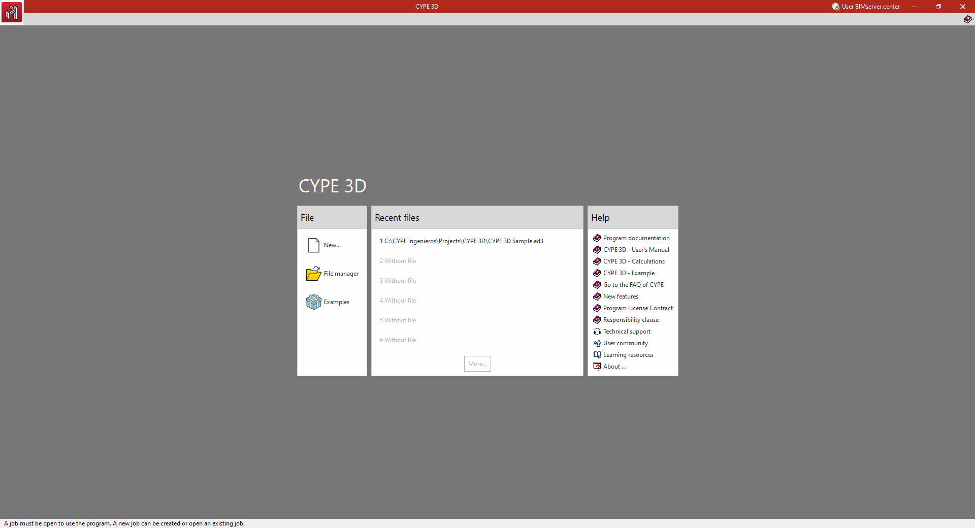
Initial interface
When the program is opened, a window is displayed with the following sections: "File", "Latest files" and "Help".
- On the left, in the "File" section, the following options can be found:
- New
Creates a new job. - File management
Accesses the program's file manager, where it is possible to search for jobs in any folder on the local disk or in the network environment, copy them, delete them, share them via web links or compress them in CYP format, among other options. - Examples
- Installs and opens any of the sample jobs that are built into the program by default, overwriting the existing ones.
- New
- In the central part, the "Recent files" section shows a report with the paths of the last jobs worked with the program. Any of them can be opened by clicking on them.
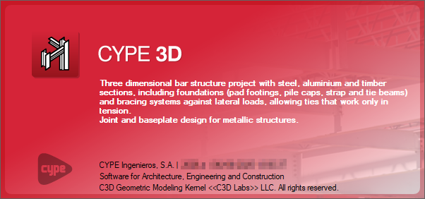
- On the right, the "Help" section offers a series of informative documents and links. From "About" the version of the program and the type and number of the licence used can be found.
The options described above can be accessed at any time from the "File" and "Help" menus at the top of the interface.
New job
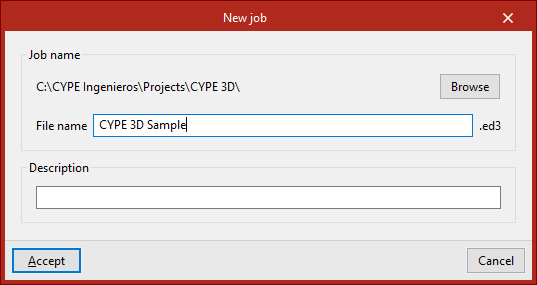
To create a new job, select "New" in the initial interface.
The program opens a dialogue box where you enter the file name and description.
By default, the program hosts the files in the path shown, but this can be changed by clicking on "Browse".
| Note: |
|---|
| CYPE 3D will save the model information in a file with extension .ed3. A backup copy with the .ed$ extension will be automatically generated along with it. This file can be renamed to a file with the .ed3 extension if the information it contains is to be retrieved. In the work process, an .ed3_dat folder will also be generated in the same path with additional information about the model. |
Empty job/Automatic IFC entry
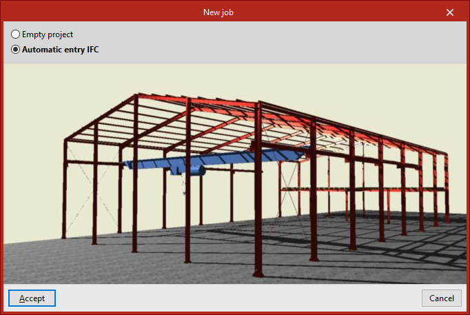
When clicking "Accept", the program opens the "New job" window, which displays a choice of two options:
- The "Empty job" option is used to create a new job in which all the data for floors, groups, columns, beams, slabs and other elements must be entered manually.
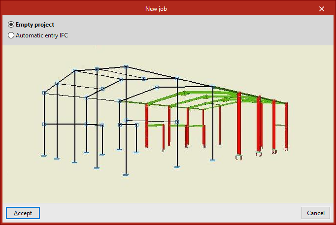
- From "Automatic IFC introduction", the information can be imported from IFC files from other programs that include the definition of the analytical model, from which the links between bars and the diagram of their layout are obtained. If this option is selected, after accepting this window, a wizard opens to guide users through the import process.
General data and limit states
In the process of creating a new empty job, the window for defining the general data of the structure opens. Here, the codes and materials to be used, the loadcases and other analysis options are configured.
This information can be configured at this moment or later from the "General data" option in the "Job" tab.
When clicking on "Finish", if this has not been done previously, the information corresponding to the "Limit States" must be validated by accepting the window that appears.
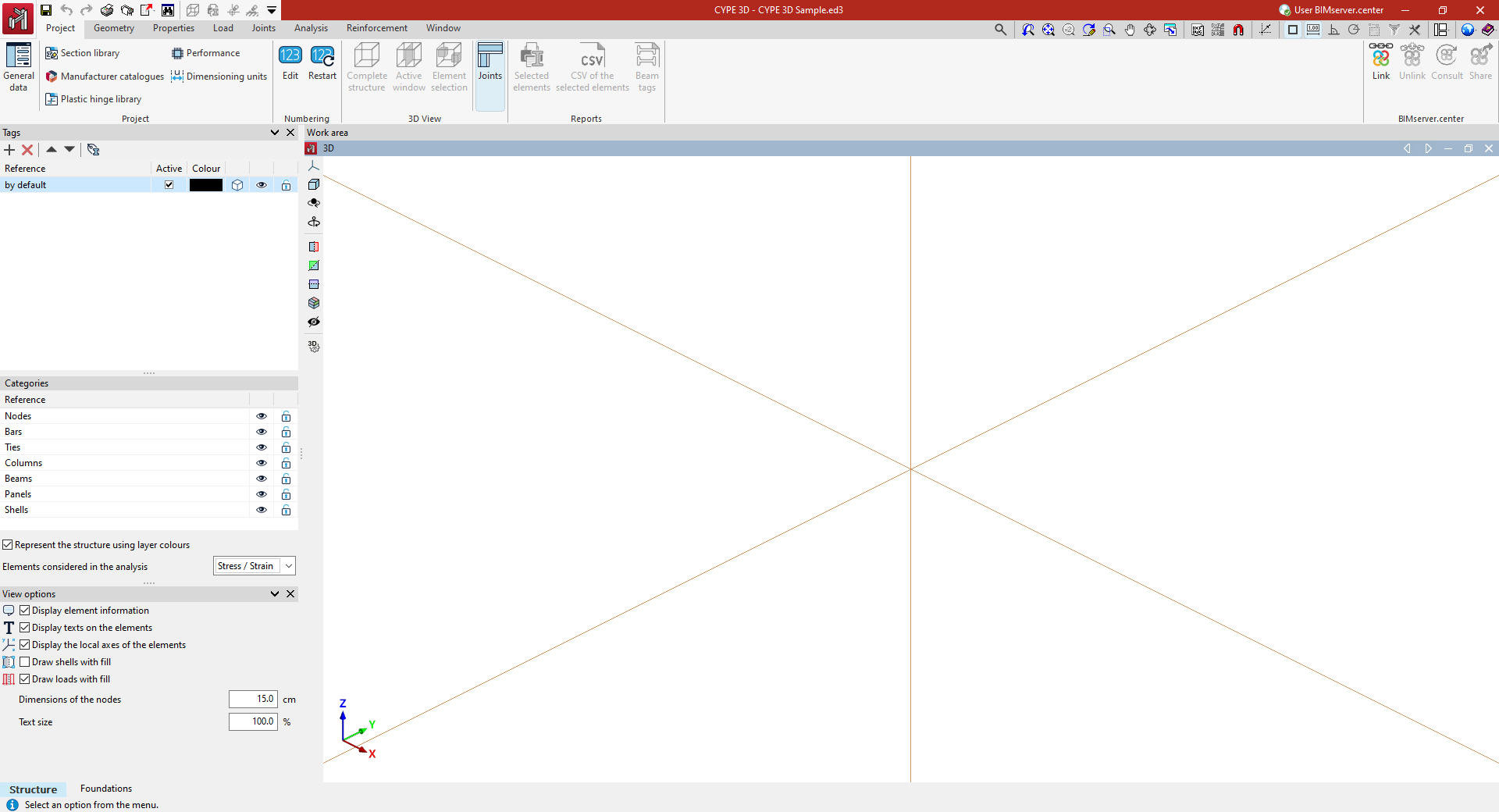
Entering in the program's general interface
Finally, the program opens the general interface via the "Job" tab (in the "Structure" tab), where model data can start being entered.
Automatic input from importing IFC files
CYPE 3D allows the import of structural analysis models from IFC files.
The structural analysis model in IFC files is analogous to the model defined by a user in CYPE 3D and is composed of structural-type entities such as nodes and bars. In addition, the relationships between nodes and bars are defined explicitly through connection conditions.
Access to automatic input from IFC files
Automatic input from IFC files is carried out during the creation of a new project. To do this, in the "New project" window, select the "Automatic IFC input" option.
This opens an import and data-entry wizard consisting of the following stages.
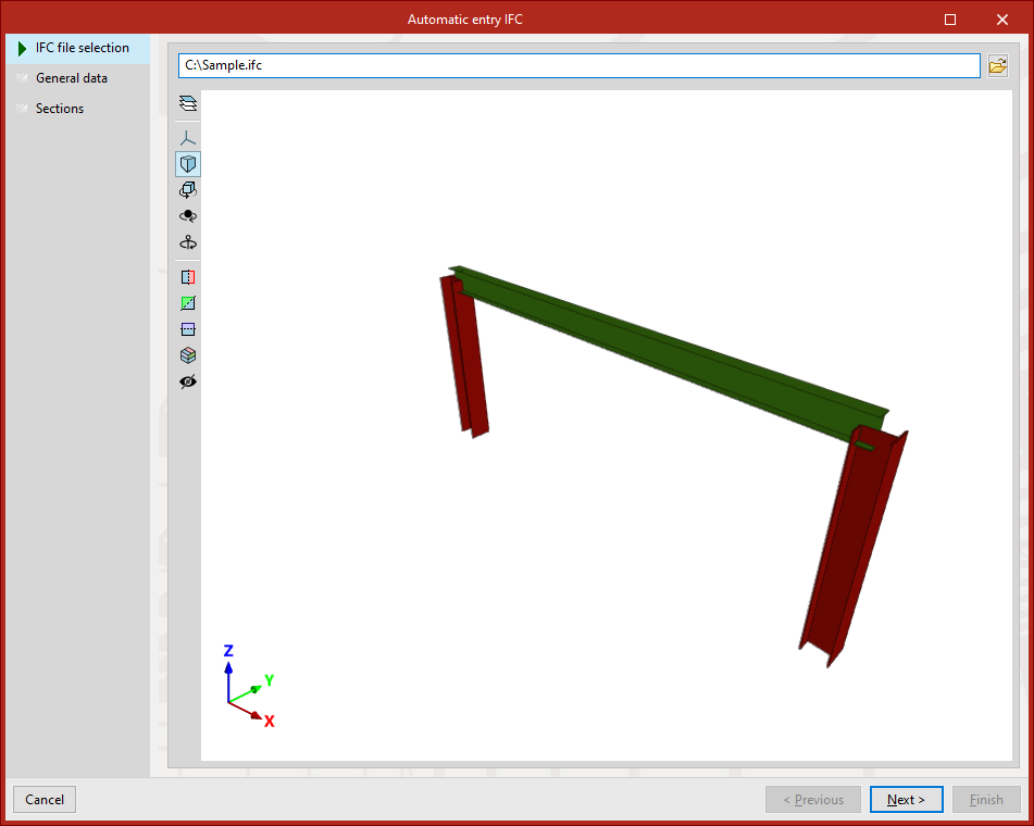
IFC file selection
At this stage, the IFC file containing the information to be imported is selected.
| Note: |
|---|
| IFC files that only include the physical model and not the structural analysis model do not contain any information that CYPE 3D can read. Via this link, you can consult the IFC entities imported during the process. |
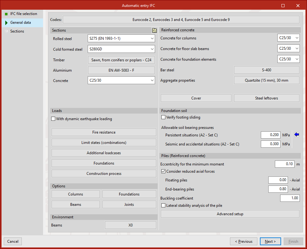
General data
At this stage, as in the creation of an empty new project, the general data of the project must be defined. Here, the applicable codes and materials, load cases, and other calculation options are configured.
You can set this up now or come back to it later in Project > General data.
When clicking "Next", if it has not been done previously, the information corresponding to the "Limit states" must be validated by accepting the window that appears.
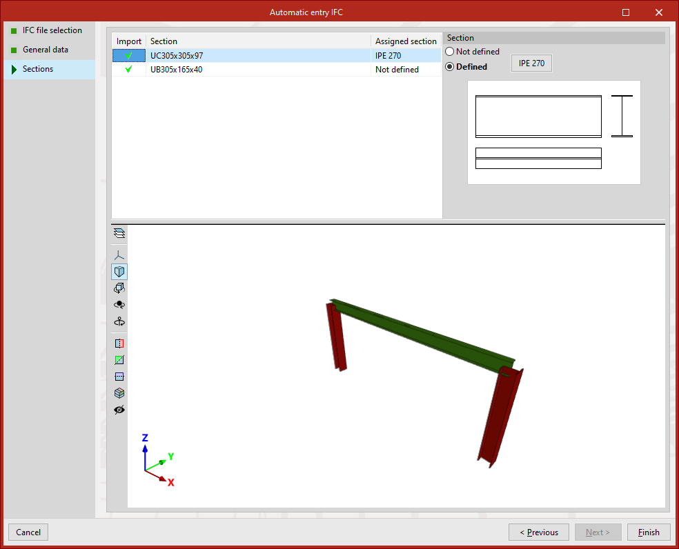
Sections
At this stage, a list is displayed with the bar-type entities (IfcStructuralCurveMember) that the program has identified in the IFC file:
- To activate the import of each one, tick the "Import" box in the left-hand column.
- Further to the right, the name of each "Section" in the file is shown, as well as the "Assigned section" in CYPE 3D.
- By default, each section appears as "Not defined". To assign a section, select "Defined" and click the button next to it. This opens the "Describe section" window, where you can select a section type or create a new one in any of the section libraries available in CYPE 3D.
In any case, it is possible to describe the sections later via the "Section" option in the "Geometry" tab.
Import result
After completing the wizard by clicking "Finish", the main interface of the program will open in the "Project" tab (in the "Structure" sub-tab), allowing you to continue working to complete the model and carry out its calculation.
In the workspace, the nodes and bars imported from the IFC file will be displayed.
IFC entities imported via the "Automatic entry IFC" process
CYPE 3D allows you to import data contained in IFC files using the "Automatic entry IFC" option, available when creating a "New project".
The IFC entities that contain information readable by CYPE 3D are as follows, and include beams, with their end support conditions and descriptions, and joints, with their external connection conditions:
| Model | IfcStructuralAnalysisModel |
| Nodes | IfcStructuralPointConnection |
| Bars (with defined sections) | IfcStructuralCurveMember |
| Boundary conditions | IfcBoundaryNodeCondition |
| Relationships between nodes and edges | IfcRelConnectsWithEccentricity / IfcRelConnectsStructuralMember |
These entities correspond to structural analysis models and not to physical models. If the selected IFC file does not contain these IFC entities, CYPE 3D will not be able to generate any information following the import process, displaying the message "This file does not contain any analysis models that can be imported". If this is the case, you should review the options available in the program used to create the IFC file to incorporate information into the aforementioned IFC entities.
Example: Exporting from SAP2000® to CYPE 3D
In the case of SAP2000®, you can use the following export options to generate an IFC file containing elements that can subsequently be imported into CYPE 3D:
- "Create IFC File" window
- "File Format" section
- IFC diagram: IFC 2x3
- Model View: Structural Analysis
- "File Format" section
Table of contents
Complete your CYPE 3D journey by exploring the other available sections:
- Introduction
- Start: creating new projects, workflows, and examples
- Setting the work environment
- Setting the job data
- Defining the structure’s geometry
- Editing the properties of structural elements
- Entering and editing loads on the structure
- Designing and analysing connections
- Analyses, checks, and results
- Defining and editing reinforcement
- Designing and analysing foundation
- Printing documents and exporting data