
Options in the "Foundation" tab
The lower tab "Foundation" contains the tools for the design and calculation of the foundation elements. The upper ribbon includes:
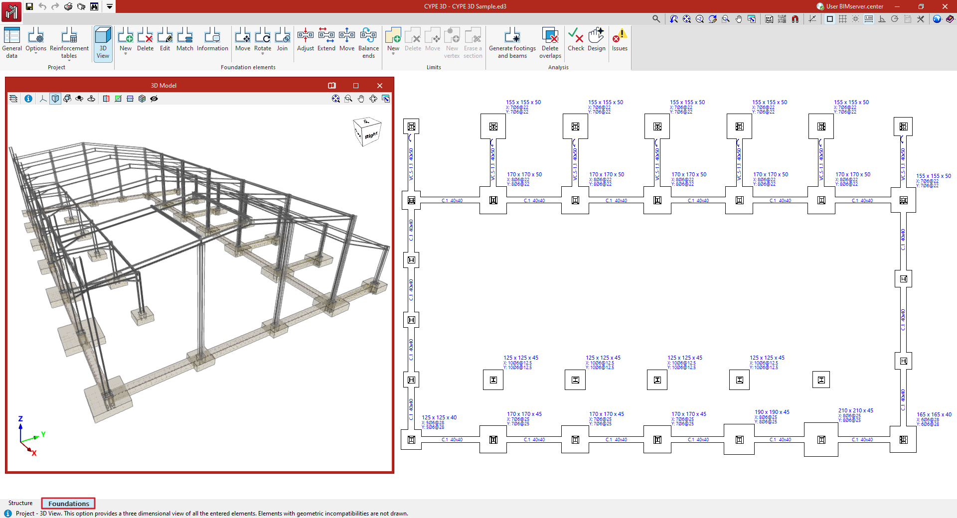
- in the "Job" group, the options for configuring the general data of the foundation, its analysis and design options, and the reinforcement tables, as well as for obtaining the 3D view;
- in the "Foundation elements" group, the options for entering the foundation elements (footings, pile caps, tie beams and centring beams), as well as options for editing and adjusting them;
- in the "Limits" group, the options for entering and managing footing polygonal limits;
- and in the "Analysis" group, the options for the automatic generation of footings and beams, and for the analysis, checking and design of foundation elements, as well as for the display of events.
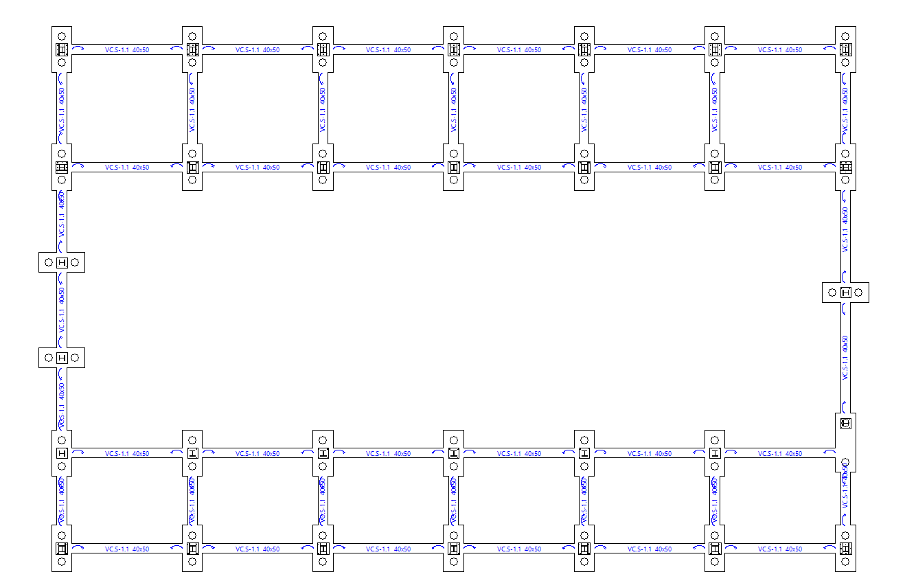
The display of this tab shows the starts of the vertical bars entered in the "Structure" tab, which have an external fixity defined at their base with fixed displacements.
Configuring general foundation data
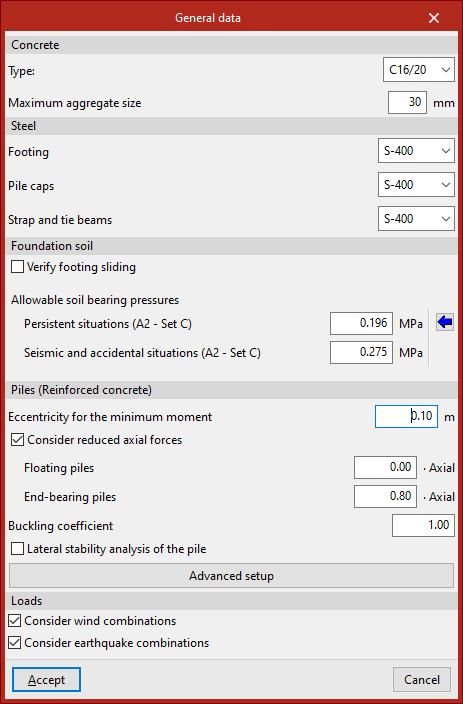
To review the general foundation settings in the program, go to the "Foundation" tab and select the "General data" option in the "Project" section at the top of the interface.

Material settings
Firstly, the data relating to the materials used in the foundation elements are defined:
- In "Concrete", the "Type" of concrete and the "Maximum aggregate size" are specified.
- Next, the type of "Steel" used for "Footings", "Pile caps" and "Strap and tie beams" is specified by selecting it from the various drop-down menus.
The materials available depend on the code selected.
Terrain settings
In the "Foundation soil" section, you can tick the "Verify footing sliding" box to include a slippage check in the design and verification of the footings.
The resistance to sliding is calculated using the Mohr-Coulomb failure model, that is, as the sum of the product of the "Adhesion (a')" and the compressed surface area of the footing, plus the product of the compressive axial force and the tangent of the "Soil-footing friction angle (d')".
In the boxes on the right, the program allows you to enter the information required to carry out this check.
Next, the values of the allowable soil stresses are entered for both "Persistent situations" and "Seismic and accidental conditions", also referred to as design forces in some standards.
You can "Import usual project values" by clicking the button on the right.
| Note: |
|---|
| The allowable bearing pressures have already been reduced by a safety factor. Due to differences in this factor, the values proposed for allowable stress in seismic and accidental situations are higher than those specified for steady-state conditions. |
Designing reinforced concrete piles
In the "Piles (Reinforced concrete)" section, the following options and data relating to the calculation of reinforced concrete piles are configured:
- Eccentricity for the minimum moment
- Consider reduced axial forces (optional)
- Floating piles (reduction factor · Axial)
- End-bearing piles (reduction factor · Axial)
- Buckling coefficient
- Lateral stability analysis of the pile (optional)
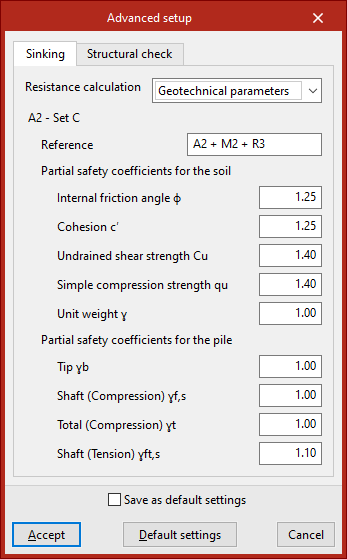
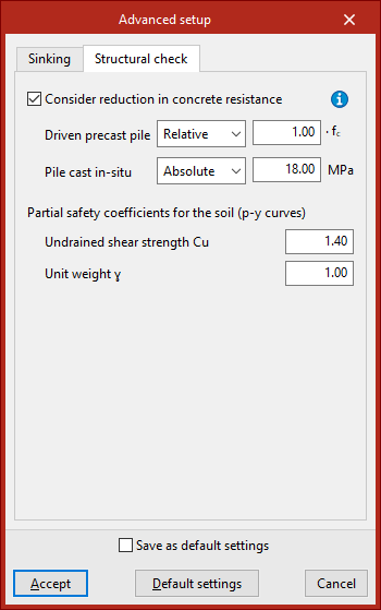
You can also access the "Advanced settings" panel, where the parameters used in the "Sinking" and "Structural analysis" checks are defined in their respective tabs.
Configuring the combinations of loads to be considered
Finally, in the "Loads" section, the program allows you to tick the "Consider wind combinations" and "Consider seismic combinations" boxes so that the foundation analysis takes into account design combinations involving wind or seismic loads, respectively.
Finally, to confirm the changes, click "Accept".
Configuring foundation options
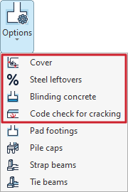
The foundation configuration tools are available in the "Options" menu within the "Project" section at the top of the interface, under the "Foundation" tab.

The general settings available in this menu are as follows:
- Cover
- Steel leftovers
- Blinding concrete
- Code check for cracking
Each of these features is described below.
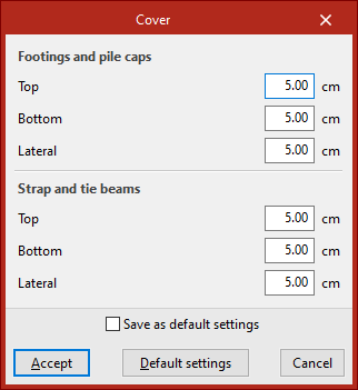
Cover
This option allows you to define the "Covers" for the reinforcement.
These may differ for "Footings and pile caps" and for "Strap and tie beams".
In each of these, you can enter a value for the "Top", "Bottom" and "Side" overlays.
If the "Save as default settings" box is ticked, the settings you have defined will be used when opening new projects. Clicking on "Default settings" will restore the program's default settings.
To apply the changes, click "Accept".
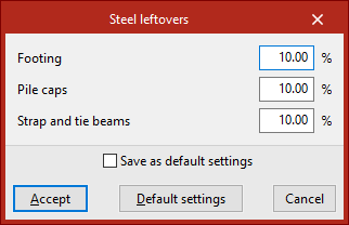
Steel leftovers
This option allows you to define a percentage for "Steel leftovers" for "Footings", "Pile caps" and "Strap and tie beams". The allowance represents an additional quantity of steel that is included in the project's measurement schedules.
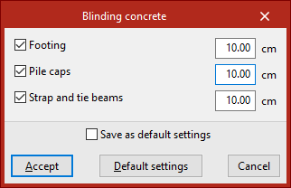
Blinding concrete
This option allows you to specify the thickness of the "Blinding concrete". You can include this in "Footings", "Pile caps" and "Strap and tie beams" by ticking the relevant boxes and entering the value.
The concrete cover is included in the quantities of the structural elements, but is not taken into account in the structural checks.
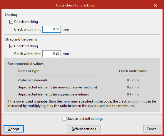
Code check for cracking
If you wish to perform the "Code check for cracking", click on the option of the same name and tick the "Check cracking" boxes under both "Footings" and "Strap and tie beams".
The program allows you to enter the "Crack width limit" value for each case. At the bottom of the window, the program displays a table of "Recommended values" based on the "Element type", which helps you to determine the value of this limit.
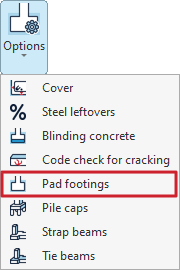
Configuring the options for pad footings
The configuration options for pad footings can be accessed by selecting "Pad footings" from the "Options" menu in the "Structure" section at the top of the interface, under the "Foundations" tab.
Clicking this option opens the "Pad footings" window, which contains the following tabs:
- General
- Perimeter reinforcement
- Types
- Stiffness criteria
- Pressure increment
Each of these is detailed below.
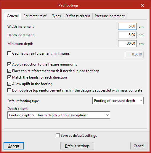
"General" tab
The "General" tab contains a range of options for the design and verification of footings.
Firstly, you can modify the "Width increment" and "Depth increment" that the program uses for each direction in successive iterations of the design process.
Next, the "Minimum depth" for all footings on the job is specified.
Next, by ticking the relevant box, you can modify the design value of the "Minimum geometric reinforcement" required to resist bending. These values are used only in the design process, not in the verification.
The following options are shown below:
- If "Apply reduction to flexure moments" is selected, the program applies the reduction in the mechanically permissible value specified by the standards during the verification.
- The "Place top reinforcement mesh on if needed in pad footings" option allows you to place an upper reinforcement mesh if required by the structural analysis. This may be necessary if uplifts are detected in the footing that generate negative moments.
- The "Match the bends for each direction" option sets the two flanges on all bars in a given direction to the maximum value obtained by calculation.
- If "Allow uplift in the footing" is disabled, the program forces the resultant force to pass through the central core.
- You may also choose the "Do not place top reinforcement mesh if the design is successful with mass concrete" option, in which case the tensile strength of the concrete is taken into account. However, the flexural analysis is always carried out as a reinforced concrete section.
Next, select the "Default footing type" for automatic generation from the drop-down menu, choosing either "Footing of constant depth" or "Tapered footing".
The flange dimension is selected at the bottom; this can be the result of the analysis or a flange dimension greater than that of the beams.
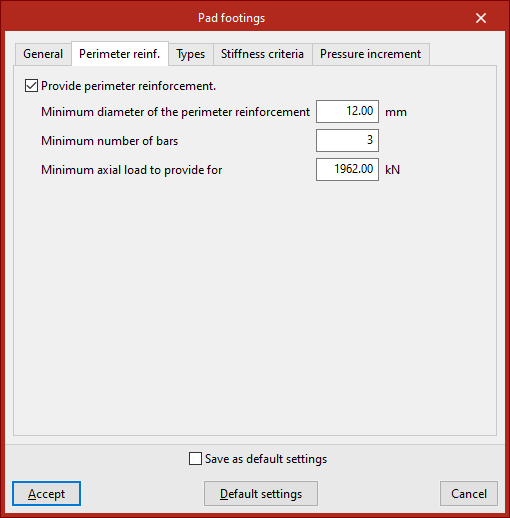
"Perimeter reinforcement" tab
The "Perimeter reinforcement" tab indicates whether you wish to include perimeter reinforcement.
The program will use the first diameter in the list that is equal to or greater than the specified "Minimum diameter". The "Minimum number of bars" and the "Minimum axial force" required for that reinforcement must also be specified; the latter must be exceeded by the maximum axial force in the most unfavourable concrete combination.
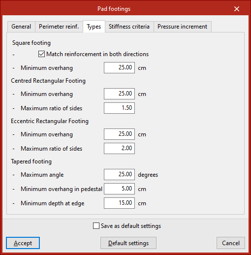
"Types" tab
This tab is used to define design criteria for different types of footings.
For square footings, you can tick the "Match reinforcement in both directions" option for each grid, as well as set the "Minimum overhang" in all directions.
For both centred and eccentric rectangular footings, in addition to the "Minimum overhang", the "Maximum aspect ratio" is specified, i.e. the ratio of the greater width to the lesser width.
For tapered footings, the "Maximum angle", the Minimum overhang in pedestal" (in directions where the building is neither a party wall nor a corner unit) and the "Minimum depth at edge" are specified; the latter is the lowest permissible value for the depth in the design calculations.
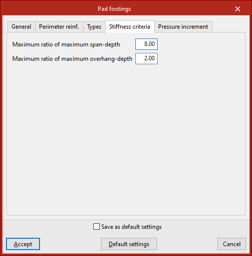
"Stiffness criteria" tab
In the "Stiffness criteria" tab, you define the "Maximum ratio of maximum span-depth" for a footing to be considered rigid, and the "Maximum ratio of maximum overhang depth" permitted in the design.
"Pressure increment" tab
In the final tab, the program allows you to set a maximum "Pressure increment" transmitted to the ground relative to the permissible value when loads are off-centre. By default, the increase is 25%.
These increments are defined for "Persistent situations without wind", "Persistent situations with wind" and "Accidental situations".
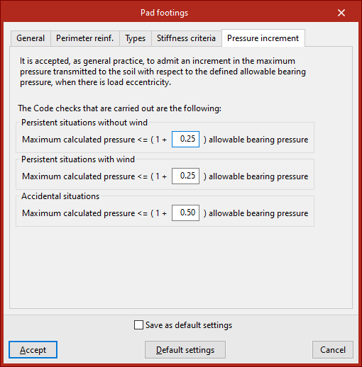
If the "Save as default settings" checkbox is ticked, the settings specified in this window will be used when opening new projects. Clicking on "Default settings" loads the default values.
To apply the changes, click "Accept".
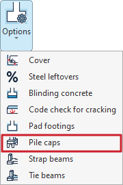
Configuring pile cap options
The settings for the pile caps are available by selecting "Pile caps" from the "Options" menu in the "Project" section at the top of the interface, under the "Foundations" tab.
Clicking on this option opens the "Pile caps" window, which contains the following tabs:
- General
- Single pile
- Pile cap beams
- Beams and meshes
- Reinforcement
Each of these is detailed below.
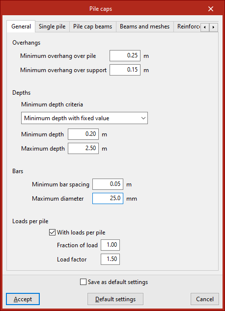
"General" tab
The "General" tab is used to set a series of criteria for the design and verification of pile caps.
Firstly, the minimum “Overhangs” for the pile cap are defined, including the “Minimum overhang over the pile” and the “Minimum overhang over the support”.
Next, in the "Bars" section, select the "Minimum depth criteria". This can be a "Minimum depth with fixed value", in which case you must enter the value in the field below, or a minimum edge based on various standards (such as EH-91, EHE or NB-1). Further down, define the "Maximum edge" of the grid.
When configuring the "Bars", you need to enter the "Minimum bar spacing" and their "Maximum diameter".
"Loads per pile" option
The "Loads per pile" option should be selected in cases where you wish to standardise the design of pile caps for a specific number of piles, even though the loads on the supports differ.
When this option is selected, the program generates a new design combination for the pile cap, assuming that the maximum load on the pile is equal to the pile’s bearing capacity (the maximum load it can withstand without failure) multiplied by the “Load safety factor” and the “Load factor” (between 0 and 1) entered in the fields below. The load fraction allows the load to be reduced if the installed pile withstands much more than it theoretically needs to bear, i.e. if it is oversized.
Normally, this combination ensures that all pile caps of the same type (same number of piles and geometry) are constructed in the same way, as it is usually the least favourable combination when using the default values, thereby simplifying the construction process.
| Note: |
|---|
| Nd = Cp × Gp × Fp, where Nd: design bearing capacity of the pile Cp: bearing capacity of the pile Gp: load safety factor Fp: load fraction |
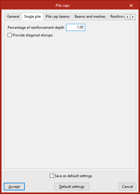
"Single pile" tab
The "Single pile" tab is used to set options for analysing the pile foundations.
The "Percentage of reinforcement depth" is the percentage of the reinforcement web depth that is intended to absorb the tensile forces arising in a concrete mass due to divergence in the compression struts. This value is used in the design to determine the effective depth of the reinforcement web.
Enabling the following option allows you to "Provide diagonal stirrups", which helps to confine the concrete in the slab. This layout is recommended where significant live loads are present.
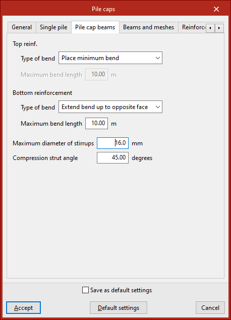
"Pile cap beams" tab
The "Pile cap beams" tab is used to define the settings required for the design of beams embedded within another beam.
Under "Type of bend", select the criteria for sizing the stirrups in the bars that make up both the "Top reinforcement" and the "Bottom reinforcement" of the beam ends:
- Extend bend up to opposite face
The bends extend to the face of the opposite wall. In this case, the "Maximum bend length" must be specified. - Place minimum bend
Bends are fitted to the minimum length necessary to ensure secure anchoring.
The "Maximum diameter of the stirrups" for the formwork beams and the "Compression strut angle" (between 30 and 60 degrees) are also specified.
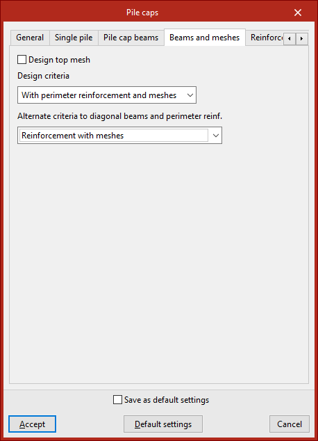
"Beams and meshes" tab
This tab allows you to specify the reinforcement layout used in the pile caps used during the design process.
Select the reinforcement layout from the following options:
- Reinforcement according to EHE code
The pile caps are assembled using side beams and meshes (in accordance with the EHE-98 standard). - Reinforcement with meshes
The pile caps are reinforced using meshes only. - Reinforcement with diagonal beams (*)
Pile caps are reinforced using side beams and middle or diagonal beams. - With perimeter reinforcement and mesh panels (*)
The pile caps are reinforced using perimeter reinforcement and mesh panels. - With perimeter reinforcement and meshes (*)
The pile caps are reinforced using perimeter reinforcement and central or diagonal beams.
For all standards, the reinforcement layout specified in the reference standard will be accepted as correct during verification; consequently, some verification results may not comply with assembly configurations other than those specified in this standard.
(*) In the case of pile caps that do not accommodate central or diagonal beams, an “Alternative approach to diagonal beams and perimeter reinforcement” must be specified. Thus, the design may be carried out in accordance with the provisions of the reference standard (“Reinforcement according to EHE code”) or by replacing the diagonal beams with meshes (“Reinforcement with truss grids”). In rectangular pile caps, all the tensile reinforcement cannot be arranged around the perimeter of the frame, as this would require a very large depth; therefore, for this type of frame, if the design is carried out using perimeter reinforcement, it is also necessary to choose one of the two alternative criteria.
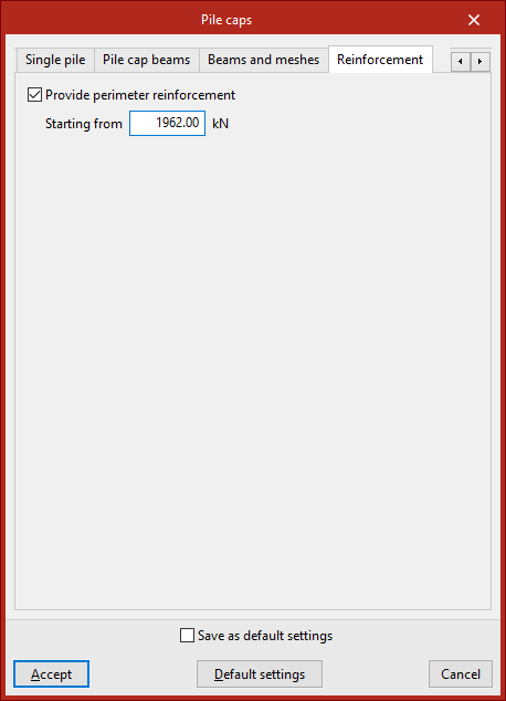
"Reinforcement" tab
In this tab, you can select the "Provide perimeter reinforcement" option to improve the confinement of the concrete in the pile cap. It is advisable to enable this option if the pile cap is subject to significant structural loads.
The load specified in the "Starting from" field refers to increased loads for the ultimate limit states of concrete. Perimeter reinforcement shall be provided when the design axial force is equal to or greater than the value entered in this field.
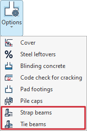
Configuring strap and tie beam options
The configuration tools for strap and tying beams can be found in the "Options" menu within the "Project" section at the top of the interface, under the "Foundations" tab.
The options available for this configuration are as follows:
- Strap beams
- Tie beams
Each of these is detailed below.
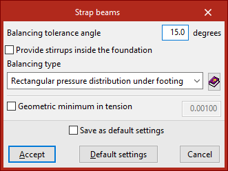
Options for strap beams
Firstly, the "Strap beams" option allows you to configure the properties of these elements.
The "Balancing tolerance angle" option is useful when the columns are not arranged in an orthogonal grid. If the strap beams near the corners of a foundation element are situated within the angle defined in this section, they will centre the bending moment of the adjacent face.
You can also select "Provide stirrups inside the foundation" to ensure that transverse reinforcement is placed in the section of the strap beams that lies within the foundation elements, such as footings.
Use the drop-down menu below to select the type of strap. This option allows you to select the type of force distribution acting beneath the footing as the ground response, for the purpose of analysing the forces on the strap beam.
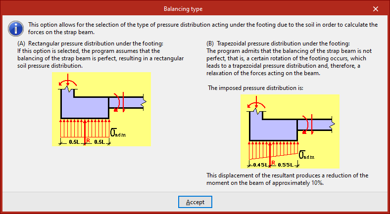
You can select either a "Rectangular pressure distribution under the footing" or a "Trapezoidal pressure distribution under footing". Clicking the button on the right will display detailed information about both options:
- In the case of the rectangular beam, it is assumed that the beam is perfectly centred.
- However, in the case of the trapezoidal law, it is recognised that the alignment is not perfect, which results in a certain amount of rotation in the bearing, a shift in the resultant force and a reduction in the stresses acting on the beam, thereby reducing the moment in the beam by a certain percentage.
Finally, by ticking the following box, you can apply "Geometric minimum in tension" requirements used in the design of strap beams. This prevents symmetrical reinforcement when footings are centred using deep beams.
To apply the changes, click "Accept".
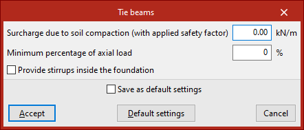
Options for tie beams
The "Tie beams" option in the "Options" submenu allows you to modify the properties of these elements.
The first two options in the pop-up window apply to tie beams as well as strap beams.
Firstly, an "Surcharge due to soil compaction (with applied safety factor)" may be considered, which may occur when the beam is constructed relatively close to the ground surface. This surcharge must be entered, increased by the safety factor estimated by the user. The program will not consider this load acting simultaneously with the tensile and compressive forces resulting from the earthquake.
The value defined under "Minimum percentage of axial load" is then used to analyse tension and compression elements. By default, this value is zero, and no axial force is applied.
If seismic actions have been defined automatically using the "With dynamic earthquake loading" option under "General data", the design acceleration is also analysed as a fraction of the gravitational acceleration, and the higher of the two values is then applied.
Finally, as with the strap beams, the last checkbox allows you to "Provide stirrups inside the foundation", so that transverse reinforcement is placed in the section of the tie beams that lies within the foundation elements, such as footings.
Once again, the changes are applied by clicking "Accept".
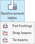
Configuring foundation reinforcement tables
The reinforcement tables for foundation elements are configured using the options in the "Reinforcement tables" menu within the "Structure" section at the top of the interface, under the "Foundations" tab.

From this menu, you can configure:
- the reinforcement tabless for the insulated footings,
- the reinforcement tables for strap beams,
- and the reinforcement tables for the tie beams.
Each of these options is described below.
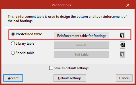
Reinforcement tables for pad footings
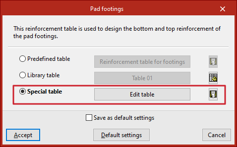
Click on the first option to configure the tables for "Pad footings". These tables are used to dimension the lower and upper reinforcement for these elements. Here, you can use the predefined or default table, one of the tables from the library, or a table specific to the project.
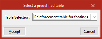
Predefined table
Tick the "Predefined table" box if you wish to use the program's default table in the analysis. To do this, click the middle button and select it from the drop-down menu. This table cannot be deleted or edited.
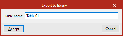
By clicking the button on the far right, you can "Export the reinforcement table to the library", then enter the "Table name". Library tables can be used in other projects.
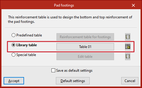
Library table
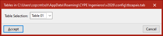
You can use any of the available library tables by ticking the "Library table" option and selecting it from the drop-down menu that appears when you click the centre button. This menu displays the reinforcement tables exported from the other options, as well as tables created from scratch via the library table editor. At the top, the program displays the file path where the tables are saved.
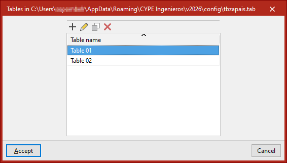
If you wish to "Edit the library tables", click the button on the right. This will take you to the list of assembly tables. You can "Add", "Edit", "Copy" or "Delete" any of them.
Special table
The "Special table" option allows you to use a custom reinforcement table for the current project. When you select this option, the table that was previously selected is duplicated.
You can then edit the data in the table by clicking on "Edit table".
Using the button on the far right, you can "Export the custom table to the library" by clicking the button on the right and then entering the "Table name".
Editing reinforcement tables for isolated footings
When editing a reinforcement schedule for isolated footings – whether a library table or a site-specific table – the program displays a series of reinforcement “Diameter(s)”, along with their “Spacing”, and the “Minimum depth” and “Maximum depth” of the elements where each entry can be applied. Any of these parameters can be modified by clicking on the relevant cell.
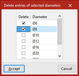
At the top, there are tools to "Add", "Copy" or "Delete" table entries, as well as "Delete selected diameter entries".
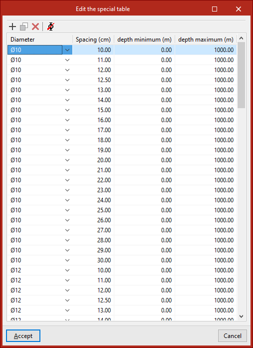
Finally, click "Accept" to use the selected table and confirm the changes.
Assembly diagrams for strap beams and tie beams
The operation of the reinforcement tables for "Strap beams" and "Tie beams" is very similar and offers the same options as the reinforcement tables for isolated footings; you can also use predefined, library or special tables.
Editing reinforcement tables for strap beams and tie beams
The reinforcement tables for strap beams and tie beams are used to determine the dimensions of the beam cross-sections, as well as the reinforcement layout.
Therefore, if you use the "Edit table" option, you will see that each entry in the table, identified by a "Reference", corresponds to a beam of a specific "Width" and "Depth".
You can change these values by clicking on each cell.
In the viewport to the right of the table, the program displays the dimensions and assembly of the selected entry.
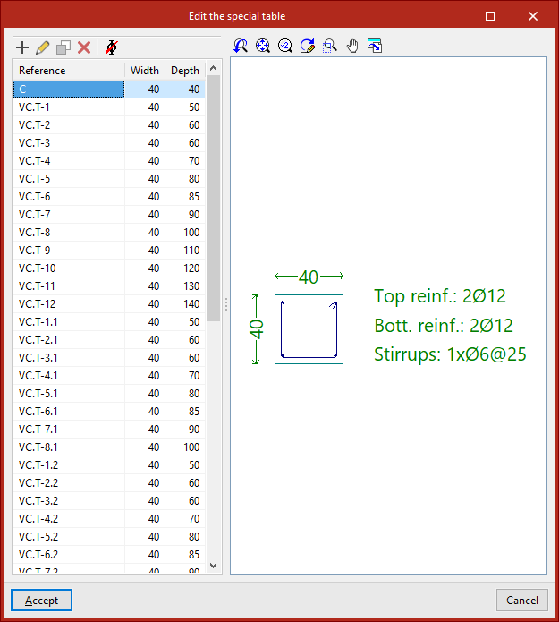
To edit the layout associated with each entry in the table, use the "Edit" button at the top.
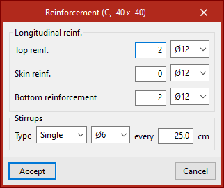
It is possible to modify both the "Longitudinal reinforcement" – whether the "Top reinforcement", "Skin reinforcement" or "Bottom reinforcement" – and the "Stirrups" of the beam, including their "Type", diameter and spacing.
Finally, click "Accept" to apply the changes.
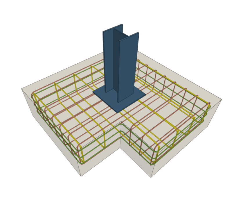
3D view of the foundations
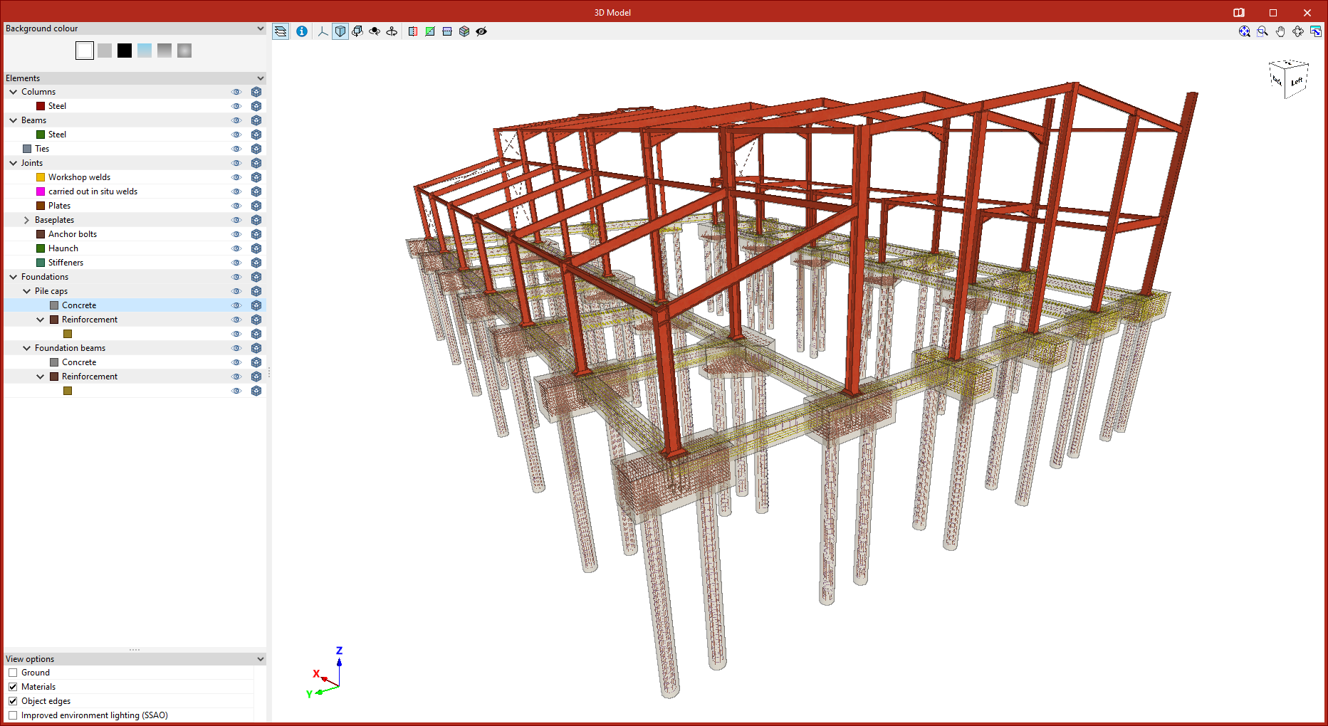
The "3D view" option, located in the "Project" section of the top toolbar on the "Foundations" tab, allows you to view a detailed three-dimensional model, including the foundations, in a separate window.

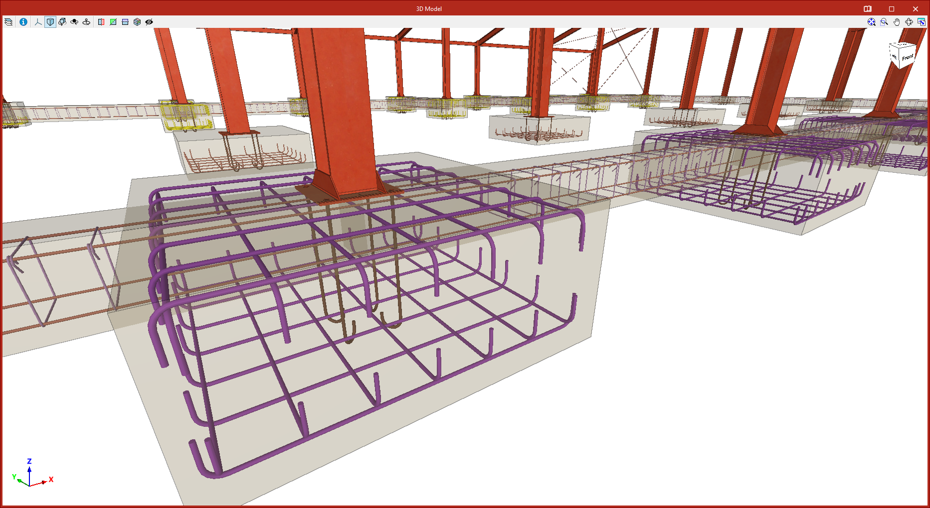
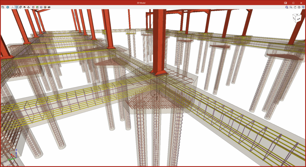
In this view, the program displays the geometry of the footings, pile caps, strap beams and tie beams, as well as the reinforcement details obtained from the analysis.
If reinforced concrete piles have been used instead of standard piles, their geometry and reinforcement are also shown.
You can view the available options in the "3D view" window via this link.
Entering foundation elements
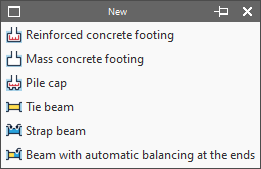
New foundation elements can be added to the model using the "New" tool in the "Foundation elements" group in the lower "Foundation" tab.

New
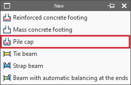
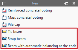
Enters a new foundation element in the model. This menu offers the following options:
- Reinforced concrete footing
- Mass concrete footing
- Pile cap
- Tie beam
- Strap beam
- Beam with automatic balancing at the ends
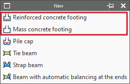
Entering footings
Footings are entered using the first two options in the "New" menu of the "Foundation elements" group, in the "Foundations" tab: "Reinforced concrete footing" and "Mass concrete footing" (without reinforcement by default).
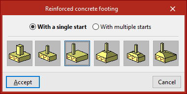
In either of the two cases, in the pop-up window that appears, you must choose "With a single start" if it is an isolated footing or "With multiple starts" in the case of a combined footing or a footing common to several columns.
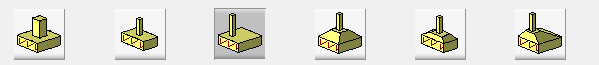
You must also indicate whether it is a square, rectangular or pyramidal footing, and whether it is centred or eccentric by choosing the corresponding type:
- Square footing
- Centred rectangular footing
- Eccentric rectangular footing
- Tapered square footing
- Tapered centred rectangular footing
- Tapered eccentric rectangular footing
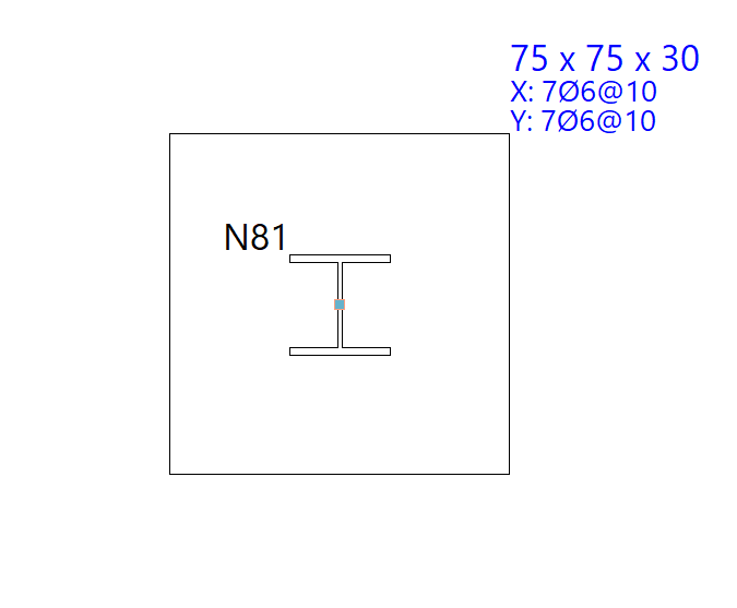
Footings with a single start (pad footings)
In this case, after clicking "Accept", the footing must be placed on the ground plan. If the mouse pointer is placed over a foundation, it takes the form of two concentric squares. If you click at this point, the foundation element will be positioned centrally under the support.
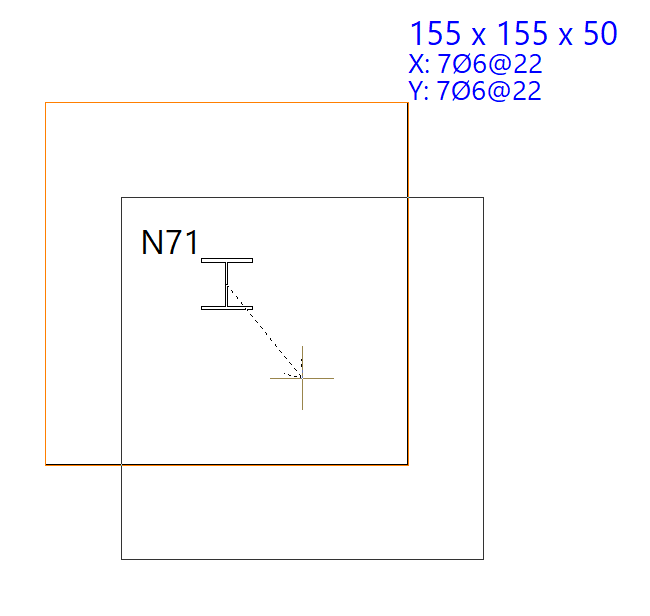
If you have chosen an eccentric footing, you can insert a corner or party wall footing by moving the mouse pointer away from the support while it is still selected. The shape of the mouse pointer indicates the shape of the footing. You can click on the support again if you want to resituate the foundation element.
Footings with more than one start (combined footings)
If you choose the "With more than one footing" option, after clicking "Accept", click on several footings to select them one by one or use the crossing method to select several simultaneously.
Then click the right mouse button. At this point, the insertion point of the foundation element appears, represented by a small circle with a cross and located at the geometric centre of the set of selected starts.
The shape of the pointer indicates the shape of the footing, just like when inserting single-start elements: centred, corner or party wall. Clicking on this point will place the foundation element under the start group.
Inserting pile caps
Pile caps are added using the "Pile cap" option in the "New" menu within the "Foundation elements" section, on the "Foundation" tab.
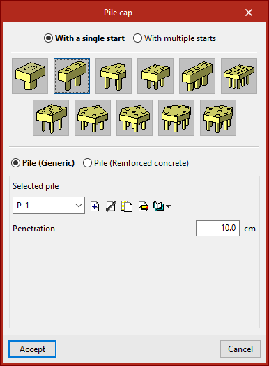
When you select this option, the pop-up window displays the "With a single start" option – if a column supports the loads of a single column – or the "With multiple starts" option – if a pile cap supports the loads of several columns.
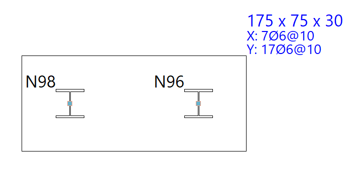
Next, select the layout of the pile cap. The program allows you to define pile caps comprising between one and seven piles, in rectangular, pentagonal or hexagonal configurations, as well as linear or rectangular pile groups with a number of piles to be specified along the X and Y axes (which can be modified via the "Edit" option within the same block, then by clicking on "Piles"):
- Pile cap for 1 pile
- Pile cap for 2 piles
- Pile cap for 3 piles
- Pile cap for 4 piles
- Strip pile cap
- Rectangular pile cap
- Pile cap for 5 piles
- Pentagonal pile cap for 5 piles
- Pentagonal pile cap for 6 piles
- Hexagonal pile cap for 6 piles
- Hexagonal pile cap for 7 piles
Below, select one of the following options:
- Pile (generic)
In this case, the general characteristics of the piles will be defined solely for the purpose of calculating the pile cap. - Pile (Reinforced concrete)
This option allows for the analysis, verification and design of piles as reinforced concrete elements, as well as the design of the pile cap.
Defining generic piles
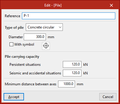
To define generic piles, under "Selected pile", click "Create" and specify the "Reference", the "Pile type", its "Diameter" or "Width" (depending on whether it is a rectangular or circular pile), and the symbol used for it.
The "Pile carrying capacity" is the maximum design service load that the column can withstand at its top, and this value must be provided by the user. The program will issue a warning if this value is exceeded following the distribution of forces calculated at the column head. This value must be defined for "Persistant situations" and for "Seismic and accidental situations".
Finally, the "Minimum distance between pile axes" is defined, which specifies the minimum distance that must exist between the centres of adjacent piles.
After clicking "Accept", you will return to the previous window. The information entered can be copied, edited or exported to libraries using the options to the right of the drop-down menu, so that it can be reused in other models.
The "Penetration" field specifies the length of the pile that penetrates the pile cap. It is recommended that you enter a value between 10 and 15 centimetres.
Inserting pile caps into the model
Once you have finished defining the pile caps and piles, click "Accept". Next, insert the pile caps onto the column starts in the floor plan by left-clicking on them.
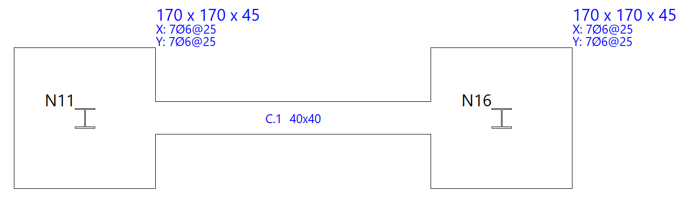
Entering tie beams and strap beams
The insertion of tie beams and centring beams is carried out with the following options in the "New" menu of the "Foundation elements" group in the "Foundation" tab: "Tie beam", "Strap beam" and "Beam with automatic balancing at the ends".
Entering tie beams
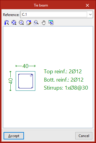
If the "Tie beam" option is selected, a pop-up window opens. In the drop-down menu at the top, the type of tie beam is selected via its "Reference".
The central display shows the dimensions and the longitudinal and transverse reinforcement associated with the selected beam type.
After clicking "Accept", the beam is entered in the plan by selecting the starting point and the end point of the beam with the left mouse button, using the snaps of the starts and the previously drawn elements if necessary.
Entering strap beam
If we select the "Strap beam" option, we must specify whether the beam "Balances at origin" or "Balances at end" by checking the corresponding checkboxes. At least one of the two check boxes must be activated. If you do not want to centre either end, a tie beam will be used.
Then, as in the previous case, select the type of strap beam in the "Reference" drop-down list and, after clicking "Accept", draw the beam in plan using the left mouse button.
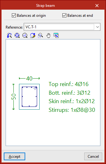
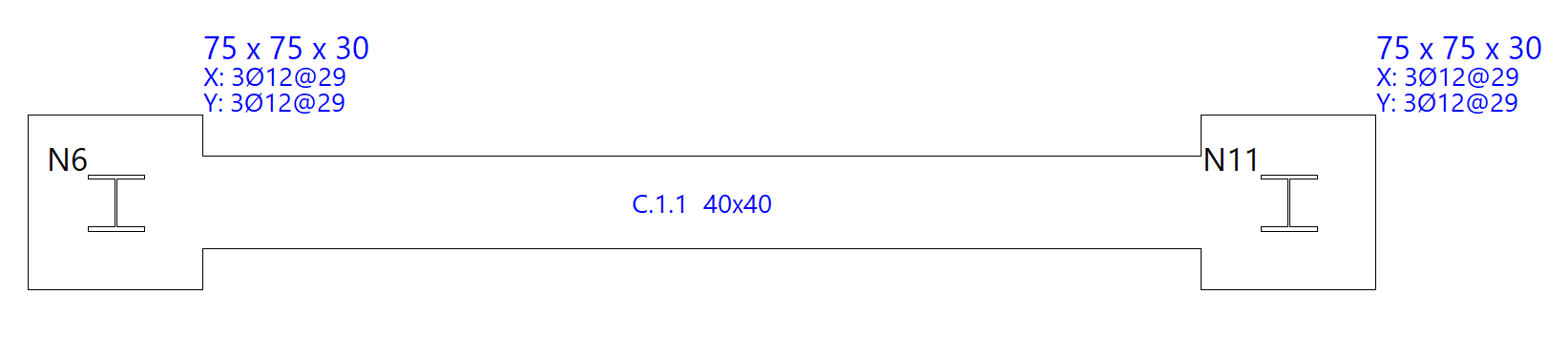
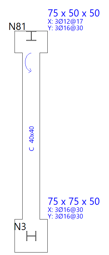
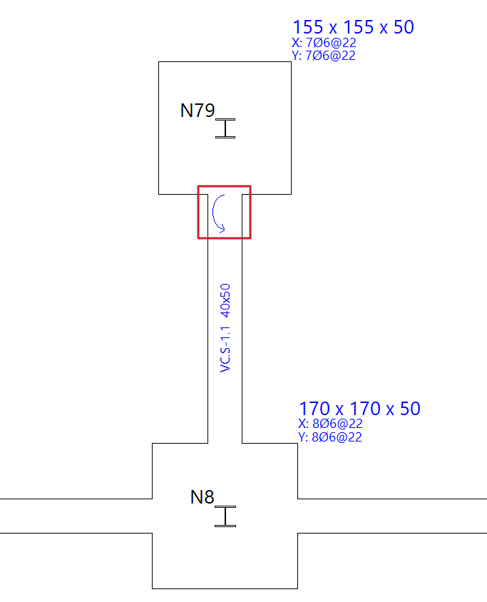
The origin and the end of a centring beam depend exclusively on the order of data entry. Once entered, we can see that circular arrows are drawn at their connection with footings or pile caps.
These arrows indicate that, at the end where they are drawn, the beam is balancing the load of the footing or pile cap in the direction of the longitudinal axis of the strap beam.
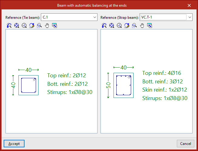
Entering beams with automatic balancing at the ends
The "Beam with automatic balancing at the ends" option allows the program to automatically identify the need for balancing loads at the ends when drawing beams in contact with corner footings or party walls.
To do this, after clicking on the option, the two possible beam types must be specified in the "Reference" drop-down menus, both in the case of a tie beam and a centring beam.
After clicking "Accept", the left button is used to enter the beam in plan in the same way as in the previous cases.
This time, the program will automatically use a tie beam if it is inserted between two centred footings, and a strap beam if one of the points of the beam is in contact with a corner or party footing, applying and displaying the centring of loads at the end where necessary.
Editing foundation elements
The following tools for editing foundation elements are available in the "Foundation elements" panel at the top of the interface, within the "Foundation" tab.

Delete
The "Delete" option allows you to delete a foundation element that has already been entered. To do this, select them one by one using the left mouse button or draw a selection area, and then click the right mouse button to confirm their deletion.
Edit
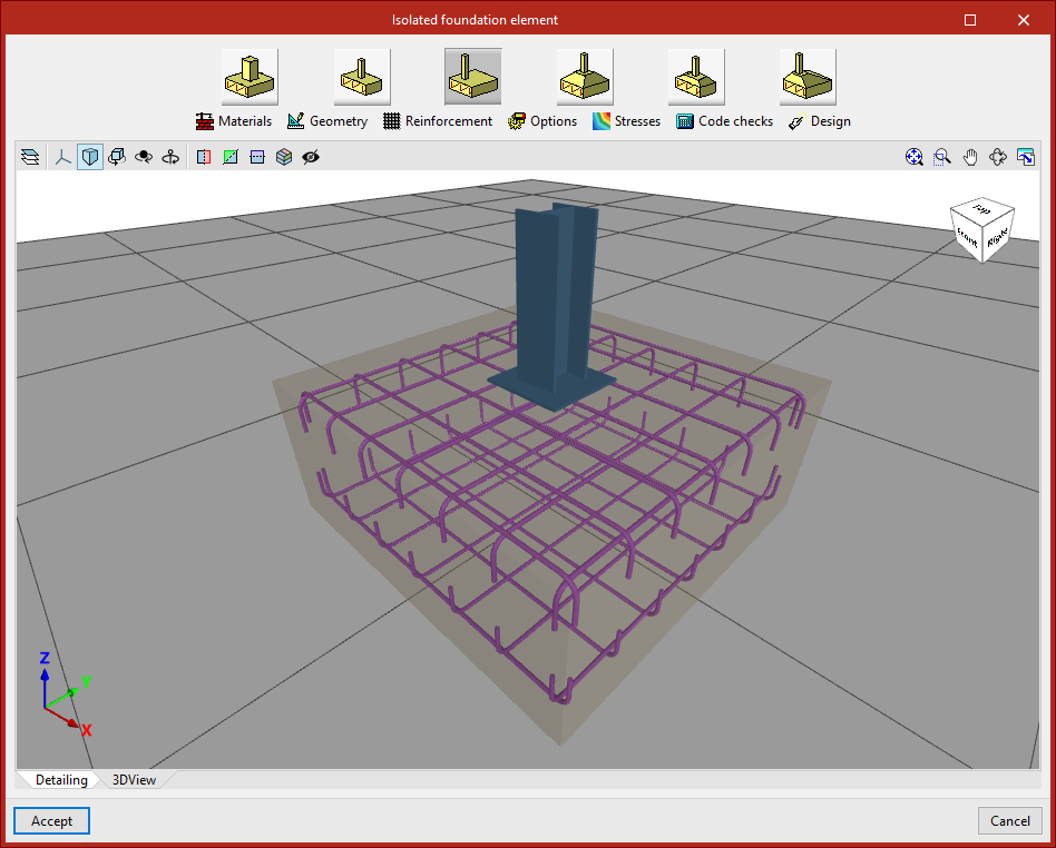
The "Edit" option allows you to modify the properties of any foundation element in a dedicated editing window, as well as perform its analysis separately, view the specific checklist, and carry out its design and reinforcement.
After selecting the option, left-click on a foundation element that has already been entered.
In the case of an isolated footing, the edit window offers the following options:
"Detailing" and "3D view" tabs
A representation of the element’s geometry and layout is displayed in the centre of the pop-up window, provided the "Detailing" tab remains visible.
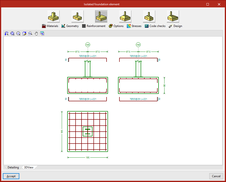
When you click on the "3D View" tab, a three-dimensional view is displayed.
Type selection
At the top of the window are tools for modifying the element's properties.
In the case of footing or pile caps, you can select a different type using the relevant buttons.
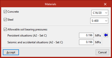
Materials
Next, by clicking on "Materials", you can assign the material properties of the element and the allowable soil bearing pressures.
If none of the boxes are ticked, the program will automatically use the information specified under "Project", "General data".
By ticking the "Concrete" or "Steel" boxes, you can select a material from those available in accordance with the selected standards.
For "Allowable soil bearing pressures", values must be defined for "Persistent situations" and "Seismic and accidental situations". Typical values can be imported by clicking the corresponding button.
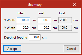
Geometry
The "Geometry" option allows you to adjust the initial and final widths in the X and Y directions, as well as the depth of the footing.
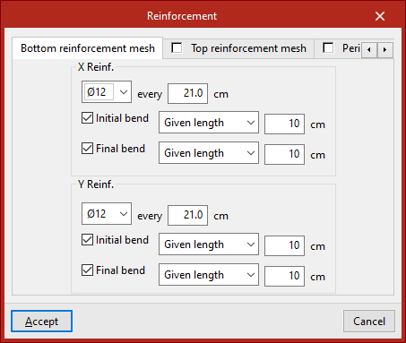
Reinforcement
To change the configuration, click on the relevant option.
In the "Bottom reinforcement mesh", "Top reinforcement mesh" and "Perimeter" tabs, the reinforcement for each part of the element is defined, including the diameter of the bars, the spacing, and whether or not there are bends.
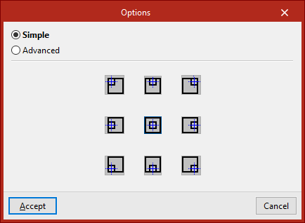
Options
You can now access the "Options" for geometric design.
- If "Simple" is selected, the program allows you to choose the direction of growth using the available symbols.
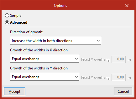
- If you tick "Advanced", you can specify which dimensions should expand and in what order. You can also specify the expansion in the X and Y directions by selecting them from the relevant drop-down menus.
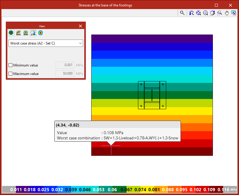
Stresses
This allows you to check the stresses at the base of the footing. To do this, the structure must be analysed.
Code checks
The element is then checked against the defined geometric and assembly conditions using the "Code check" function.
The status of each check is displayed in the centre. Clicking on a row opens the detailed report in the lower pane.
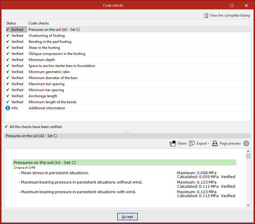
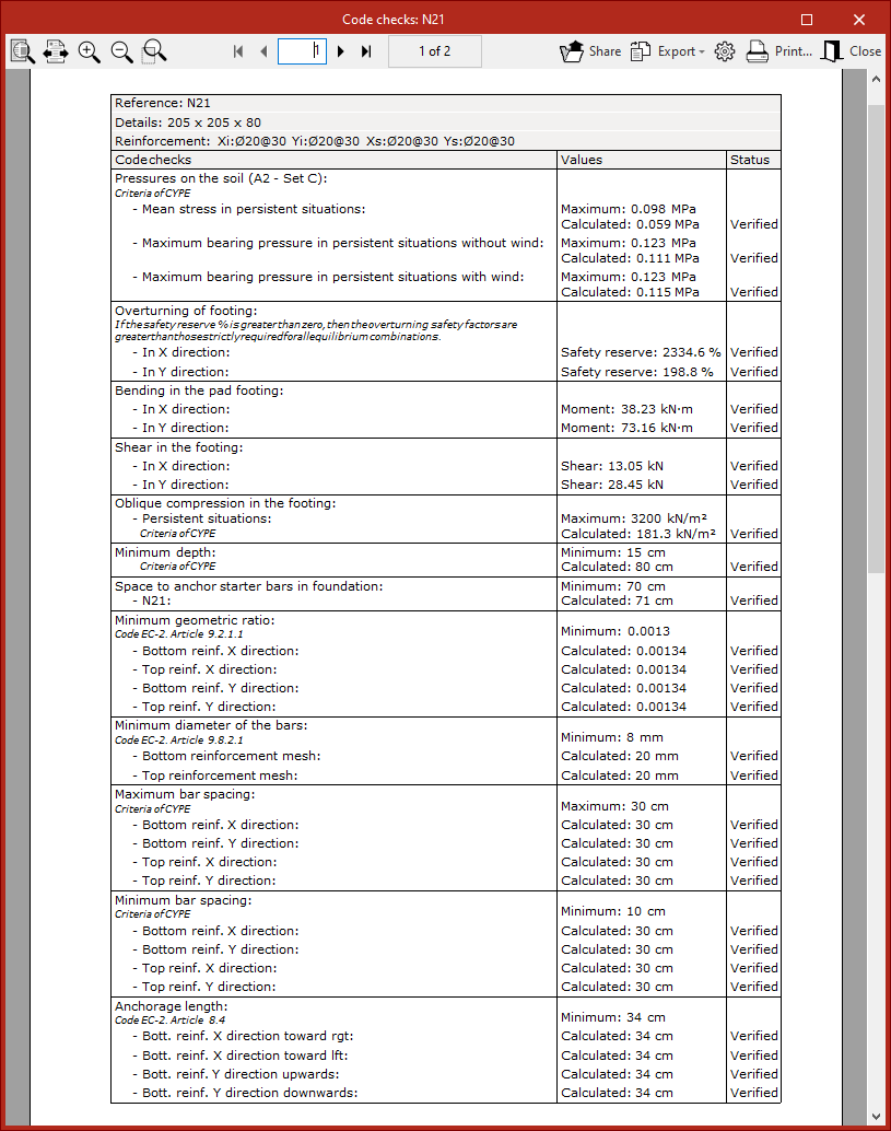
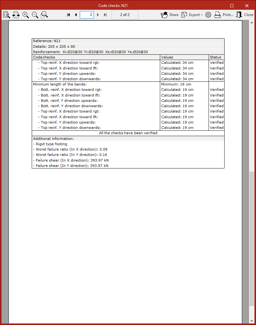
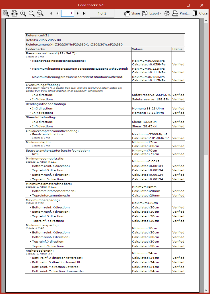
In the top right-hand corner, you can view the full report, as well as share, export or print it.
Design
Finally, using the "Design" option, you can redesign the element using the forces obtained from the analysis.
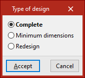
In the pop-up window, the program allows you to select the type of design:
- With "Complete", the geometry and assembly are scaled without taking the user's data into account.
- With "Minimum dimensions", the dimensions entered are retained and are only increased if necessary. The assembly is always dimensioned.
- With "Redesign", only the layout is changed, whilst the geometry remains the same.
To confirm the changes, click "Accept".
Match
The "Match" option allows you to match the type, geometry and reinforcement of different foundation elements:
- First, left-click on the element you want to obtain information about. If you select a point linked to several elements, the program allows you to choose which ones you wish to "Copy" by ticking the relevant boxes.
- After clicking "Accept", elements with different data are highlighted in yellow, and those with the same data are highlighted in orange. You can now use the left mouse button to select the items with different data that you wish to match to the selected item, or you can use a selection area.
- Right-click to complete the operation.
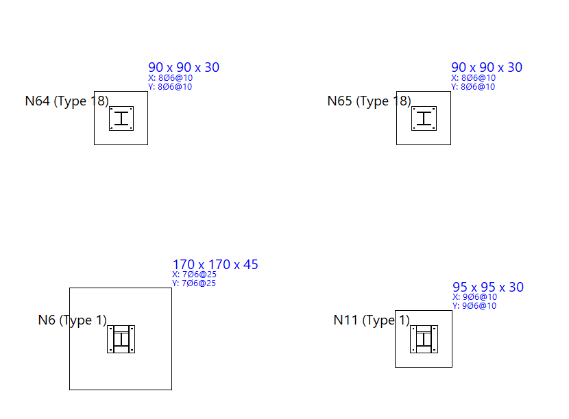
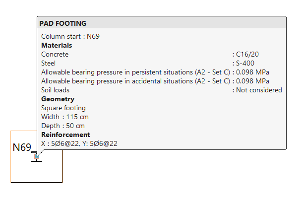
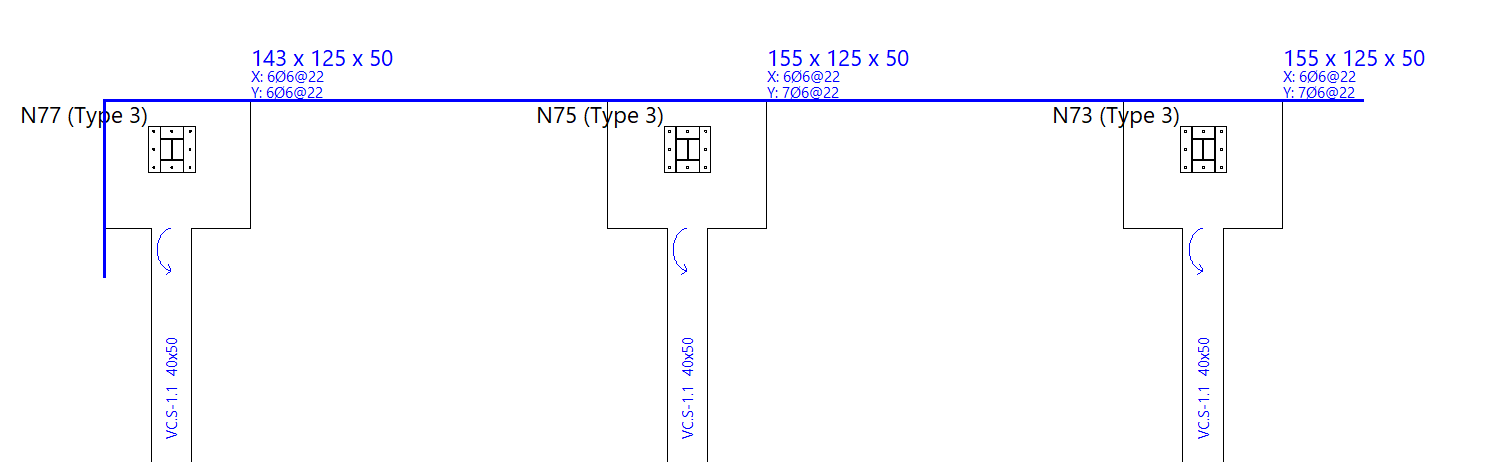
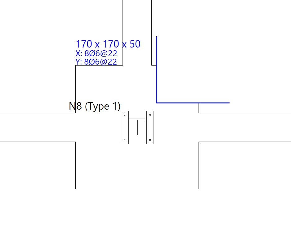
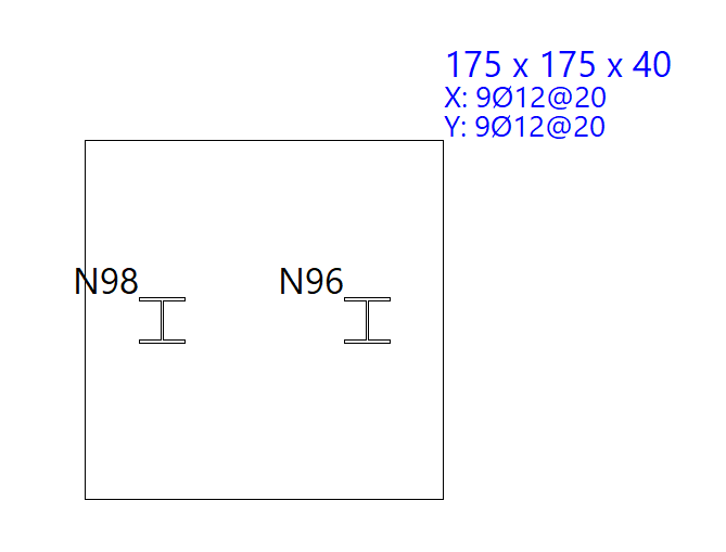
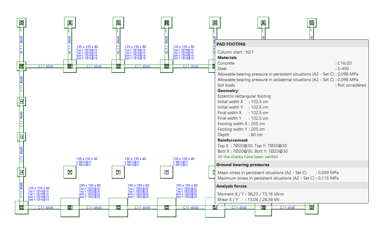
Information
The "Information" option allows you to display an information box containing the most relevant details for each item by left-clicking on it.
To hide the information text, click the right-hand button.
Adjustment options for footings and pile caps
The following tools for adjusting footings and pile caps are available in the "Foundation elements" section at the top of the interface, within the "Foundations" tab.

Move
The "Move" option allows you to adjust the position of the footings and pile caps.
To do this, after selecting the elements and right-clicking, use the left mouse button to mark two points that define the direction and magnitude of the displacement.
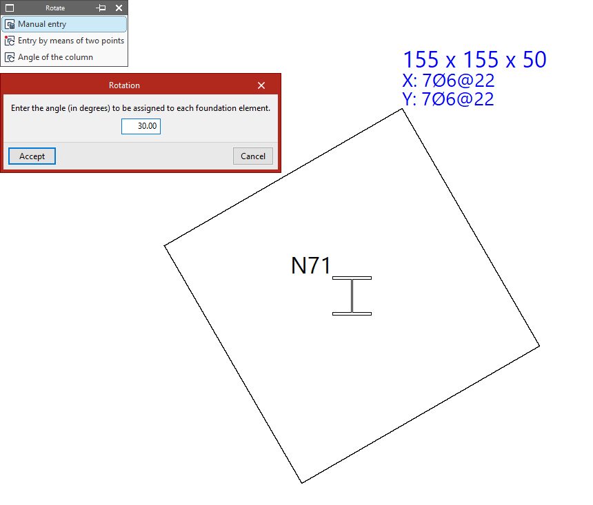
Rotate
The "Rotate" option opens a menu containing the following tools, which allow you to rotate footings and pile caps around their central axis:
- If you select "Manual entry", you must enter an angle in degrees to assign it to the foundation element. After clicking "Accept", select the elements using the left mouse button and confirm with the right mouse button.
- From the "Enter by means of two points" option, click on two points on the plan view to define the X-axis of the elements to be selected next. Then, left-click on them and confirm the operation using the right mouse button.
- If you use the "Angle of the column" option and then click on a foundation element, it will automatically adopt the column angle. If there are several columns, the angle of the first column entered will be used.
Join
The "Join" option allows you to join footings together, i.e. to assign a single footing to all columns that connect to the selected footings. You select the footings using the left mouse button and confirm by clicking the right mouse button.
This procedure does not apply to pile caps.
Adjustment options for strap and tie beams
The following adjustment tools for tie beams and strap beams are available in the "Foundation elements" section at the top of the interface, within the "Foundation" tab.

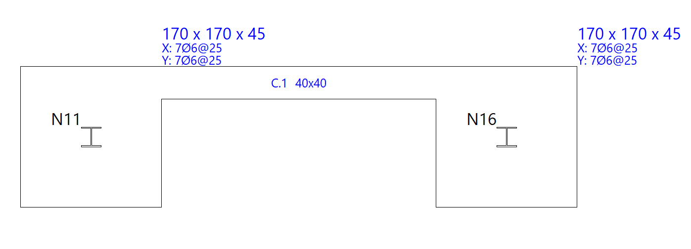
Adjust
Select "Adjust" to align one face of the beam with the furthest vertex of a foundation element.
To adjust one end, click near the face you wish to adjust. To adjust both ends at the same time—that is, the entire beam—click on the centre of the beam and on the relevant face.
The adjustment can also be made to the axes of structural members. In any case, the pointer must be kept within the beam whilst performing the operation.
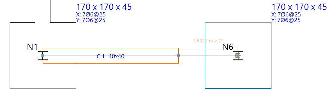
Extend
The "Extend" function moves the end of a beam along its length. To do this, left-click to select the end of the beam and then select its new position.
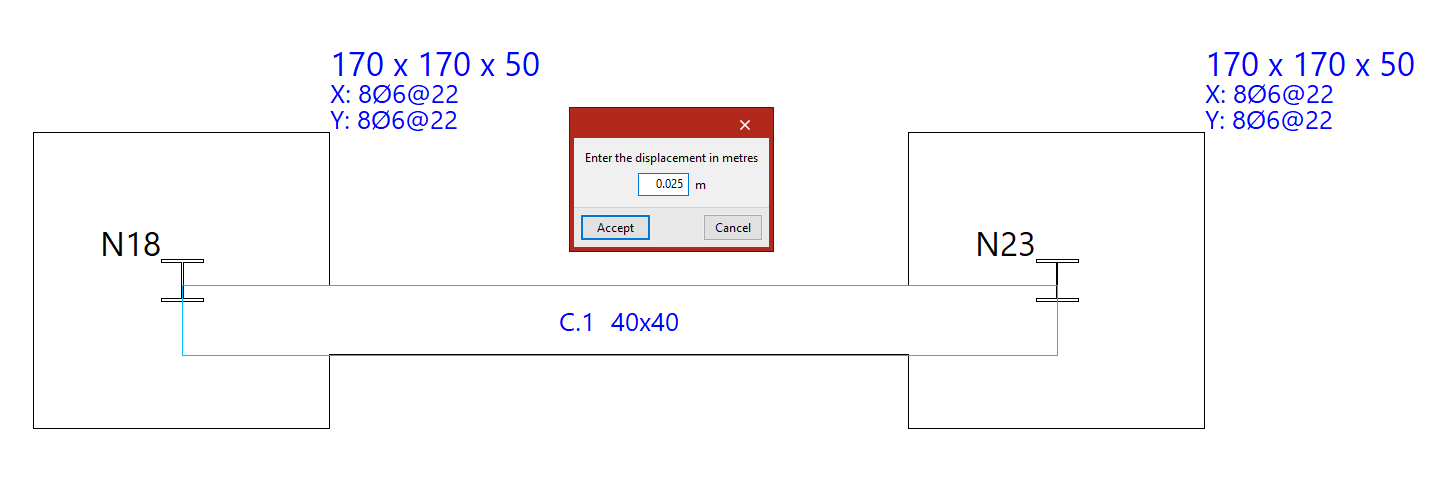
Move
Using the "Move" function, you can move the end of a beam or the entire beam. First, you must enter the displacement in the specified units of measurement.
Next, position the cursor near the end or the centre of the beam, on the side towards which you wish to move it, depending on whether you want to move just one end of the beam or the entire beam in parallel.
Balance ends
The "Balance ends" option allows you to enable or disable load centring at a specific end of a strap beam by left-clicking on that end.
If the centring beam centres the load at a specific end, a circular arrow appears to indicate that centring is enabled. If this arrow does not appear, centring at that end is not enabled.
If you click on a tie beam, you can "Change the type of beam" to a strap beam so that you can apply end centring.
Similarly, if the centring is removed from both ends of a strap beam, the program will allow you to "Change the type of beam" to a tie beam.
Entering foundation element limits
Foundation element limits are entered into the program using the options in the "Limits" group at the top of the interface, within the "Foundation" tab.

Foundation element limits allow you to define the presence of party walls, property boundaries or spaces reserved for other uses (such as lift shafts or service rooms) that must not be encroached upon by the geometry of the footings.
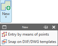
New limit
The "New" option allows you to add a new limit to the model. There are two ways to add limits:
- Entry by means of points
- Snap on DXF/DWG templates
Each of these features is explained below.
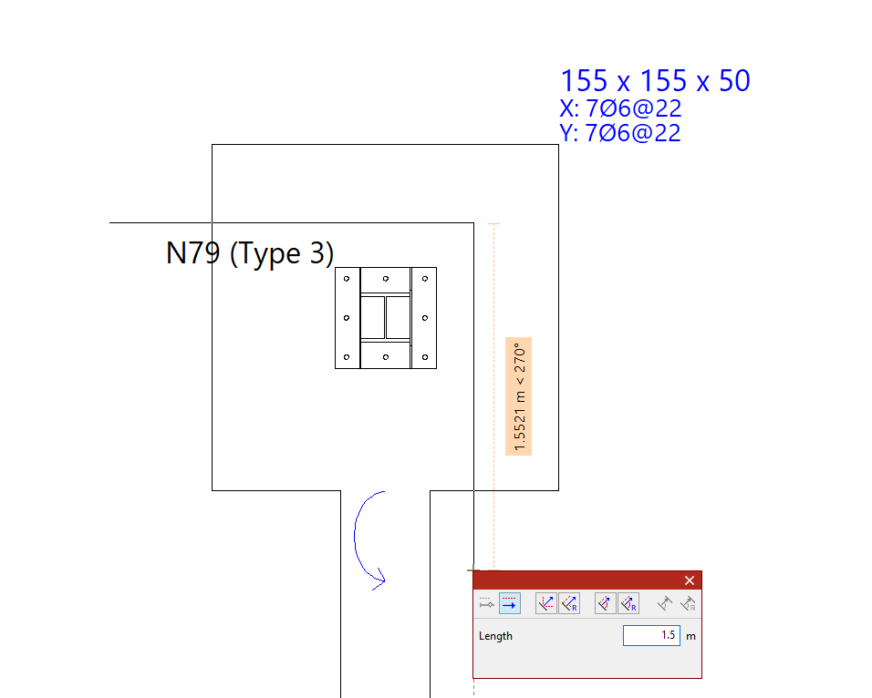
Inserting limits by points
Using "Entry by means of points", you can draw a foundation limit by left-clicking on the points or vertices that define its plan geometry. To confirm your entry, right-click.
Limits are lines or polylines that define areas which cannot be encroached upon by constant-edge footings. When added, the limit trims the geometry of any footings already entered.
The section of the sole plate that includes the pile caps is the part that is retained and taken into account in the analysis.
These limits do not apply to tie beams, centring beams, pile caps or pyramid footings.
Generating limits based on catches for templates
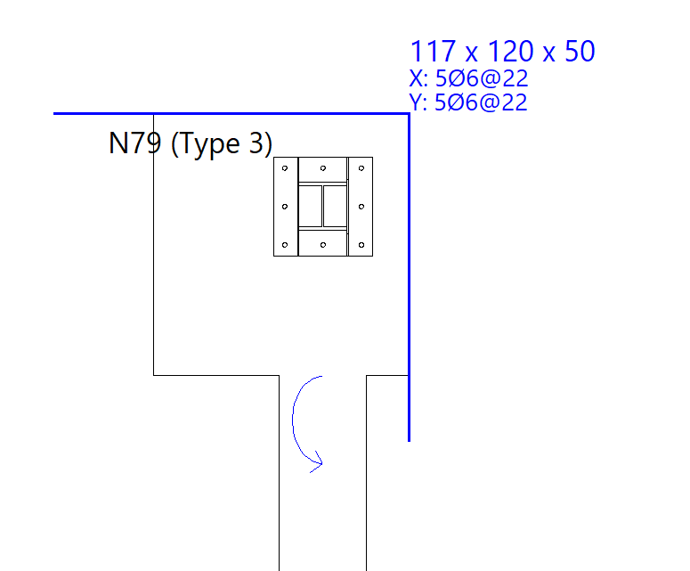
The next option, "Snap on DXF/DWG templates", allows you to automatically define a foundation limit.
To do this, after importing a DXF or DWG template, left-click on a line or polyline defined within it. The program generates a foundation limit based on the geometry of the selected element.
Deleting limits
Back in the "Limits" menu, the "Delete" option allows you to delete a previously entered foundation limit.
Select the limits to be deleted using the left mouse button or by dragging to highlight an area, then click the right mouse button to confirm their deletion.
Moving limits
Use "Move" to move a segment or a vertex of a foundation limit.
You can modify the geometry of the limit by left-clicking on a vertex to select it and then left-clicking again to set its new position.
To move a section of a foundation limit, left-click anywhere on the section and then left-click again at its new position.
Inserting new vertices at limits
Next, clicking on "New vertex" adds a new vertex to any section of an existing foundation limit.
To do this, use the left mouse button to select the element where you want to insert the new vertex, and then select the desired point.
Delete limit segments
Finally, by using "Delete a section", you can delete a section of an existing foundation limit. As before, select the sections using the left mouse button and click the right mouse button to confirm their deletion.
If an intermediate section is deleted, the limit on which it acts is split into two new limits.
Limits of foundation elements in the design process
During the design process, the program prevents footings from exceeding the specified dimensions. The design of a footing may be subject to more than one limit.
Generating, checking and designing foundation elements
The options in the "Design" group of the "Foundation" tab automatically generate footings and beams, as well as analyse, check and/or design the foundation elements, and show or hide issues.

Generating footing and beams
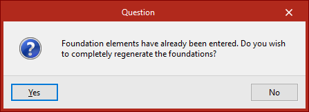
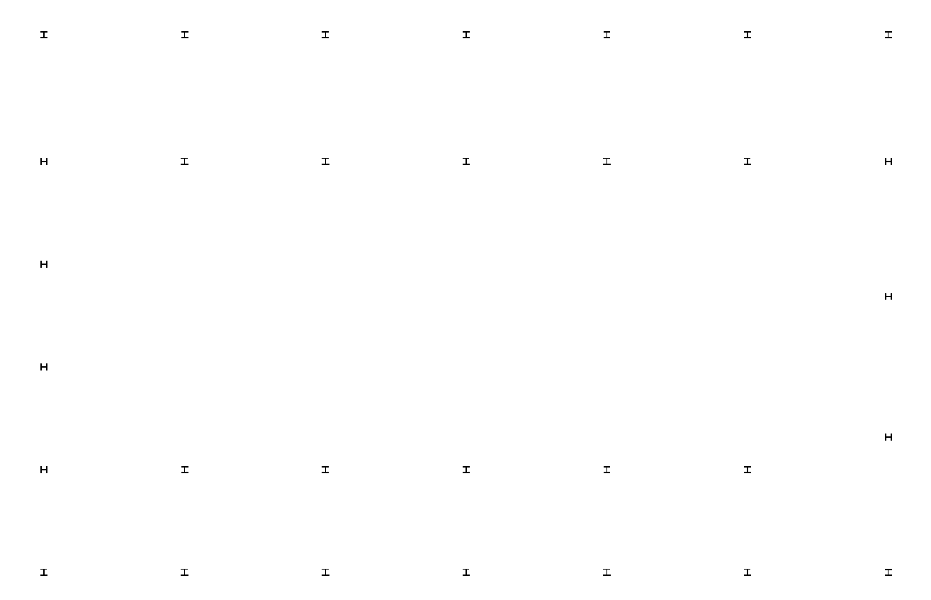
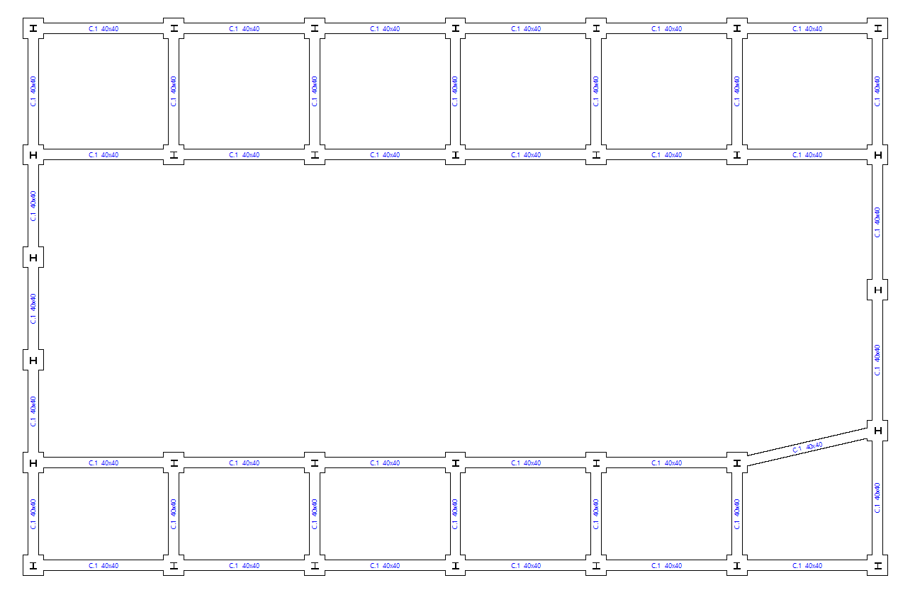
The "Generate footings and beams" option automatically creates footings and tie beams following the layout of the starting points in the floor plan.
If foundation elements have already been entered, the program then asks whether the foundation is to be completely regenerated.
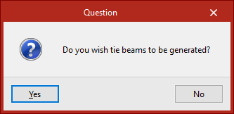
Then, in the following dialogue box, it is specified whether tie beams are to be generated.
Delete overlaps
Foundation elements overlapping with others at the same elevation may be found after manually modifying their geometry or performing the joint dimensioning of the foundation.
In this case, the geometry can be modified again to avoid the situation or the "Delete overlaps" option can be used to automatically delete the overlaps.
As a result, the program will place footings common to several starts at the places where the overlaps occur.
Check
The "Check" option checks all the elements of the foundation without making any changes, both foundations, pile caps and beams.
The elements that comply with all the checks are shown in green and those that do not are shown in red.
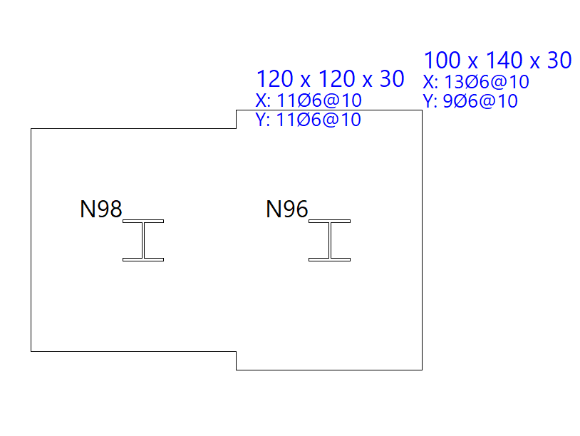
Hovering the mouse pointer over each element displays an information box with its data.
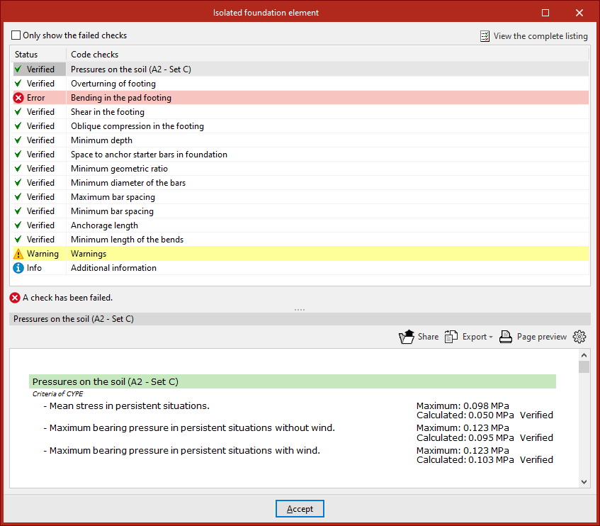
By left-clicking on each element, you can access the detailed list of checks.
By activating or deactivating the box at the top, you can indicate whether you want to "Show only the checks that are not fulfilled" or all of them.
In the central part, a list is shown with the "Status" of each "Check". By clicking on each of the lines, the detailed list of each check is displayed in the lower part of the viewer.
In the upper right-hand part it is possible to "View the complete list" of each element, which can be "Shared", "Exported" in different formats or "Print".
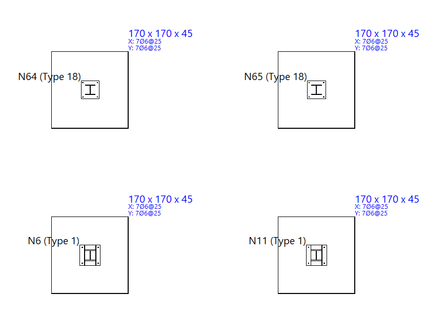
Design
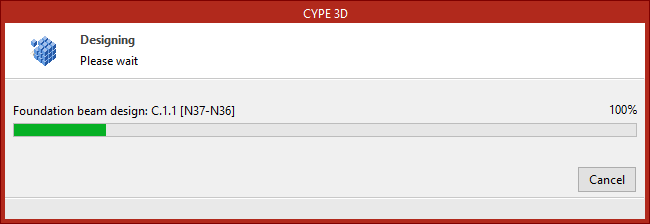
The "Design" option is used to simultaneously design the elements that make up the foundation, including both their geometry and reinforcement.
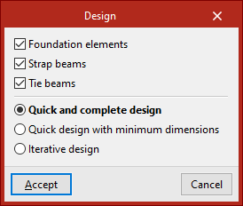
In the pop-up window that appears, the "Foundation elements", "Strap beams" and "Tie beams" boxes can be selected to define the elements to be designed.
Then, the type of design to be carried out is indicated.
- In the case of a "Quick and complete design", the design of all foundation elements is carried out in a single operation, without respecting the geometry entered by the user.
- If "Quick dimensioning with minimum dimensions" is selected, a single operation is also carried out, in this case checking the designs entered by the user and modifying them only if necessary.
- Finally, if "Iterative design" is selected, the design of all the foundation elements is carried out in three iterations, because if the stiffness of a centring beam varies, this influences the analysis of the footings to which it is linked.
After completing the design process, as with the "Check" option, hovering the mouse pointer over each element displays an information box with its data. If you click on it with the left button, you can access a detailed list of checks.
Issues
If the "Issues" option is activated, warning or error marks are displayed on the elements in which an issue has occurred.
If the mouse cursor is positioned over these marks, the error message can be displayed.
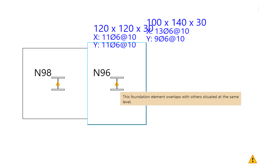
Table of contents
Complete your CYPE 3D journey by exploring the other available sections:
- Introduction
- Start: creating new projects, workflows, and examples
- Setting the work environment
- Setting the job data
- Defining the structure’s geometry
- Editing the properties of structural elements
- Entering and editing loads on the structure
- Designing and analysing connections
- Analyses, checks, and results
- Defining and editing reinforcement
- Designing and analysing foundation
- Printing documents and exporting data