Options in the "Project" tab
The upper tab "Project" (accessible within the lower tab "Structure") contains general options related to the configuration of the project and includes the following tools in the upper bar:
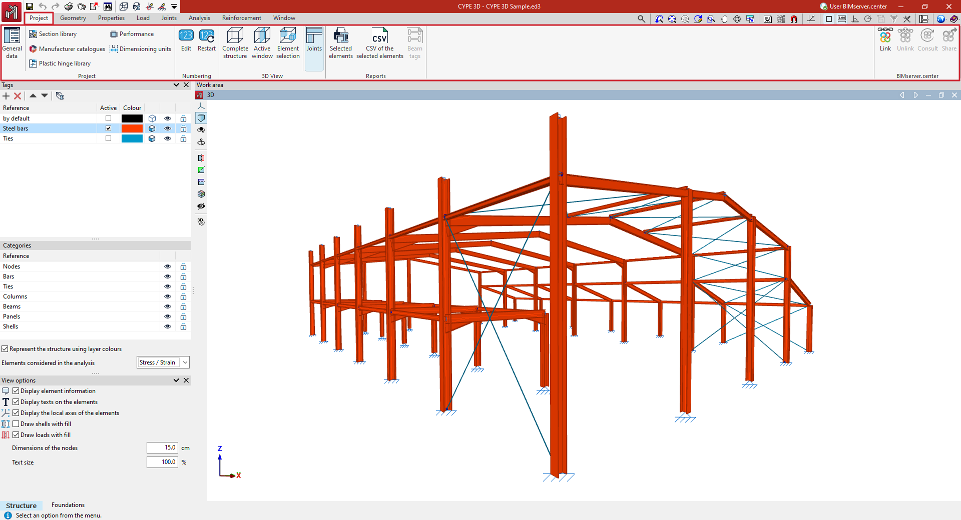
- in the "Project" group:
- access to the configuration of the general data of the project, such as the following:
- the codes to be verified;
- the materials used in the project;
- the loadcases and combinations of loadcases, including the data relating to the seismic action;
- the adjustment of other design configuration parameters, such as the reinforcement tables used or the design options for the different elements in the project.
- management of section library, manufacturer catalogues, plastic hinges library, performance options for non-linear analysis and configuration of dimensioning units;
- access to the configuration of the general data of the project, such as the following:
- in the "Numbering" group, the options for configuring the numbering of elements;
- in the "3D View" group, the options for obtaining a 3D view of all or part of the structure;
- in the "Reports" group, the options for obtaining reports and files of a selection of elements;
- and in the "BIMserver.center" group, the options for linking to a BIMserver.center project and for updating and exporting information to this platform.
Code configuration
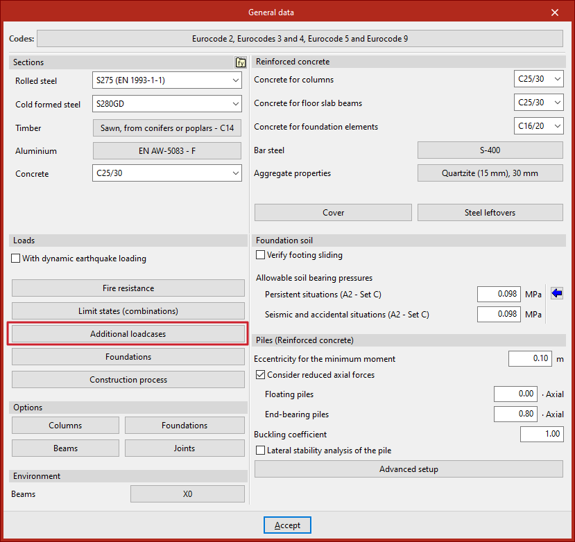
The configuration of the codes used in the analysis of the structure is done in the "Project" tab (in the “Structure” tab), by selecting the "General data" option in the "Project" group of the upper toolbar.

Code selection
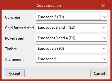
The "Codes" in the project are defined by clicking on the corresponding button.
The "Code selection" window is displayed, where the standards associated with the elements of the following materials are chosen:
- Concrete
- Cold formed steel
- Rolled steel
- Timber
- Aluminium
In each of them, we select the desired regulation from those available in the drop-down menu.
| More information: |
|---|
| The codes included in the CYPE programs can be found at this link. |
Material configuration in "Sections"
The configuration of the materials of the elements that make up the structure is carried out in the "Project" tab (in the "Structure" tab), by selecting the "General data" option in the "Project" group of the upper toolbar.
Material selection
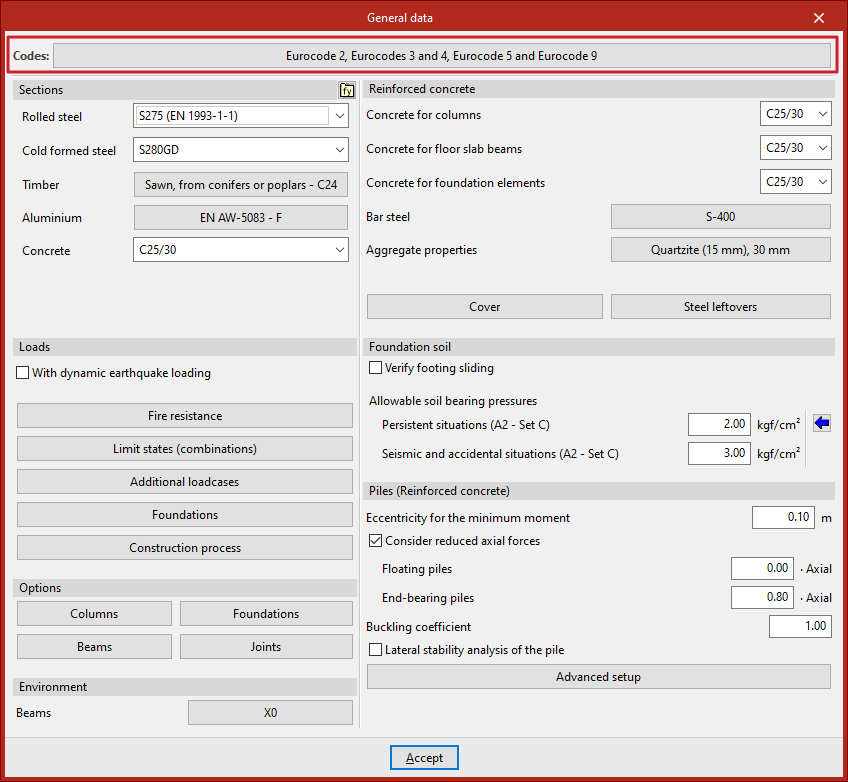
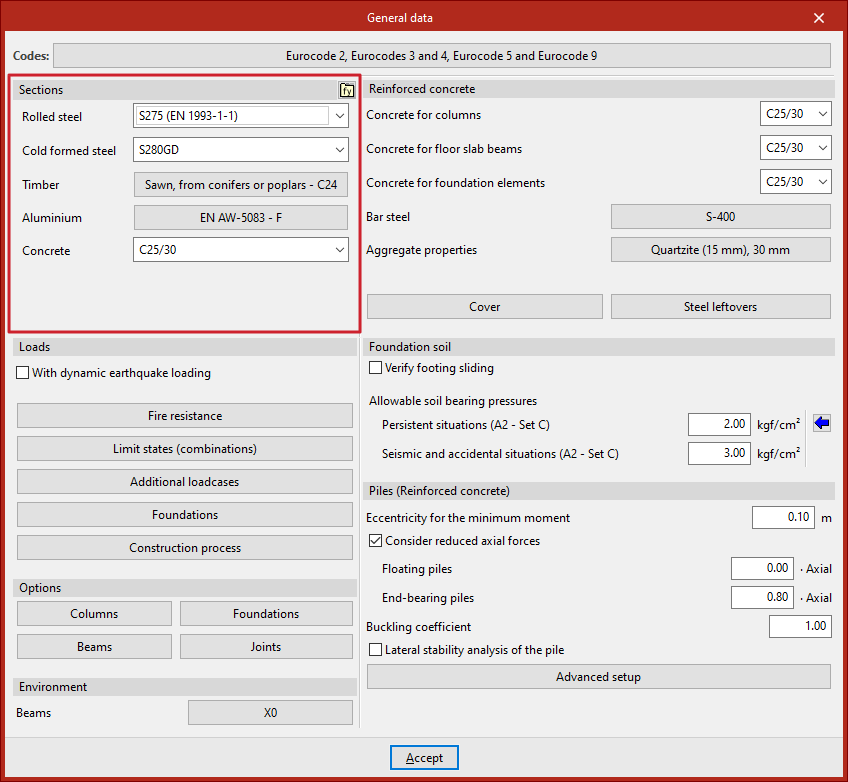
The default materials used in the project sections are defined in "Sections".
To define the steel of the sections, the drop-down menus "Rolled steel" and "Cold formed steel" are used.
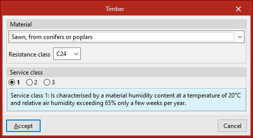
In "Timber", in the "Material" section of the pop-up window, the type of wood and the "Resistance class" associated with the elements of this material are selected. In the following sections, the "Service class" and the "Duration of the loads entered as live loads" are defined for each "Loadcase".
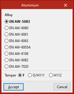
The "Aluminium" section can select the "Alloy" and the "Temper" to be applied to the aluminium elements.
In "Concrete", this material is defined for the generic concrete bars (entered from "Bar" and selecting "Generic", "Concrete bar").
| Note: |
|---|
| The materials available depend on the codes selected. |
Steel user library
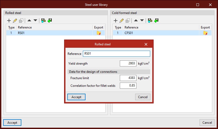
The "Steel user library" option, available in the upper right corner of the "Profiles" section, allows you to create and manage lists of user-defined steel types, either "Rolled steel" or "Cold formed steel".
For each one, a "Reference", its "Elastic limit" and, within the "Data for the design of connections", its "Fracture limit" and the "Correlation factor for fillet welds" are entered.
After creating a user steel, it can be selected from the corresponding drop-down lists in the "General data" window ("Rolled steel" and "Cold formed steel").
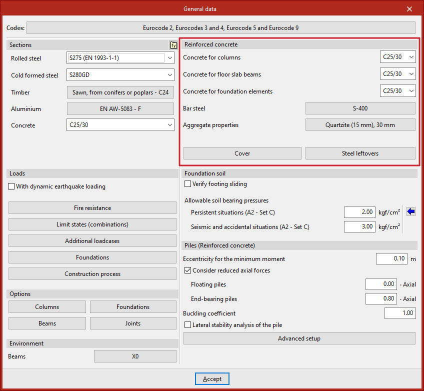
Reinforced concrete configuration
The configuration of the reinforced concrete used in the reinforced concrete elements is done in the "Project" tab (in the "Structure" tab), by selecting the "General data" option in the "Project" group of the upper toolbar.
Selecting concrete, rebar steel and aggregate properties
The characteristics of the default reinforced concrete used on site are defined in the "Reinforced concrete" section.
First, the type of concrete associated with each of the following elements is selected from the corresponding drop-down menus:
- Concrete for columns
Defines the concrete used by default in the bars entered in the "Structure" tab from the "Column" or "Bar", "Column" option. - Concrete for floor slab beams
Defines the concrete used by default in the bars entered in the "Structure" tab from the "Beam" or "Bar" option, "Beam". - Concrete for foundation elements
Defines the concrete used by default in the elements arranged in the "Foundation" tab (such as footings, pile caps, centring and tie beams).
| Note: |
|---|
| The materials shown in the different drop-down menus correspond to those covered by the selected codes. |
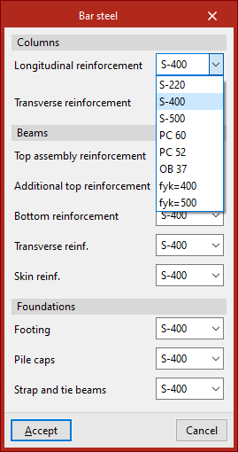
In the "Bar steel" section, the reinforcing steel to be used is selected in each of the following categories:
- Columns
Defines the steel for the following column reinforcement:- Longitudinal reinforcement
- Transverse reinforcement
- Beams
Defines the steel for the following reinforcement of floor beams:- Top assembly reinforcement
- Additional top reinforcement
- Bottom reinforcement
- Transverse reinforcement
- Skin reinforcement
- Foundations
Defines the reinforcement steel for the following foundation elements:- Footing
- Pile caps
- Strap and tie beams
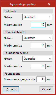
The "Aggregate properties" for each type of element ("Columns", "Floor beams", "Foundation beams" and "Foundations") are specified below.
In each case, the "Nature" and "Maximum size" of the aggregate is defined.
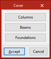
Covers
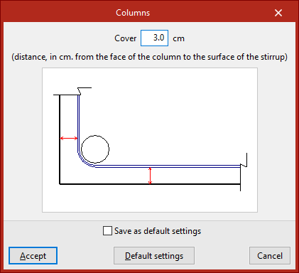
The "Covers" option can be used to define the cover for each type of reinforced concrete element:
- Columns
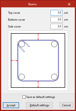
The column cover is defined as the distance from the face of the column to the face of the stirrup bar (geometric cover). - Beams
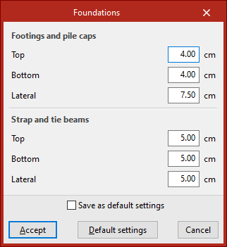
Defines the "Top cover", "Bottom cover" and "Side cover" of beams independently. In all cases, the covers are defined as the distance from the face of the beam to the face of the stirrup bar (geometric cover). - Foundation
Defines the "Top", "Bottom" and "Side" overlaps for both "Footings and pile caps" and "Tie and centering beams" independently, measured from the perimeter of the concrete section to the surface of the bars.
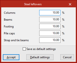
Steel leftovers
The "Steel leftovers" option can be used to enter percentages associated with steel leftovers or losses in "Columns", "Beams", "Footings", "Pile caps" and "Tie and centring beams", respectively.
These leftovers shall be considered as increments in the quantities measured automatically by the program.
Defining loadcases
The definition of loadcases for the analysis of the structure is done in the "Project" tab (in the "Structure" tab), by selecting the "General data" option in the "Project" group of the upper toolbar.
"Additional loadcases" option
The configuration of loadcases is done by clicking on "Additional loadcases" in the "Loads" section.
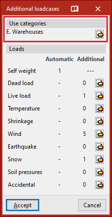
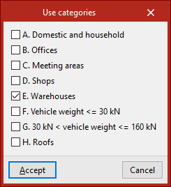
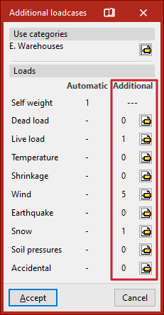
Use categories
In the "Use categories" section, all existing use categories on the job within the selected codes are declared. To do this, the edit button is used and the desired categories are activated (e.g. domestic and residential, offices, warehouses or vehicle traffic areas).
For the program, a use category constitutes a group of live load loadcases that are combined with the same combination coefficients with the other loadcases defined in the jobs.
Loadcases
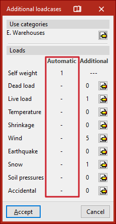
The "Loadcases" section defines the number and type of loadcases for the jobs.
Automatic loads
The "Automatic" column shows the loadcases automatically considered by the program, such as the loadcase of the "Own weight" of the structure.
If the "With seismic loading" option has been previously activated in the "General data" window, users will also find automatic loads added in the "Seismic" section, generated according to the selected codes.
Additional loadcases
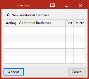
In the "Additional" column, additional loadcases can be added if needed.
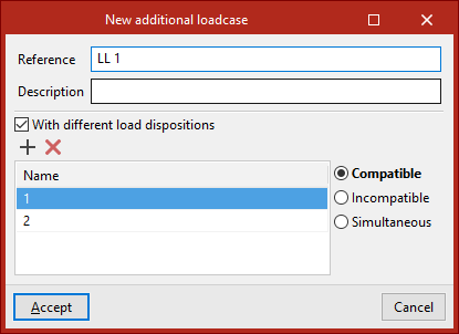
To do so, after clicking on the edit button within the desired category, click on "New additional loadcase" and indicate a "Reference" and a "Description".
Optionally, the program allows to activate the "With different load dispositions" option in each of the added scenarios. The load arrangement concept allows defining different load states grouped in the same scenario. The load arrangements can be "Compatible" with each other, "Incompatible" or "Simultaneous".
| Note: |
|---|
| If the CYPE 3D job has been generated from an export from Portal frame generator, the necessary additional loadcases will have been automatically created, such as live loads, wind loads or snow loads |
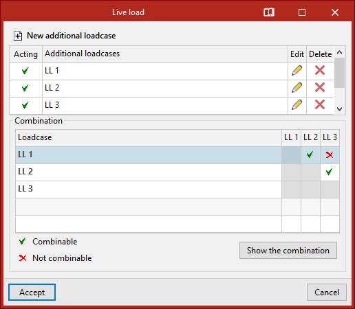
Loadcase combination
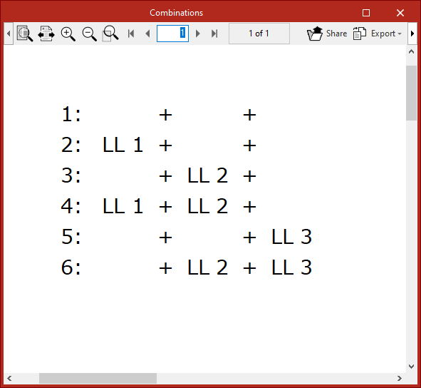
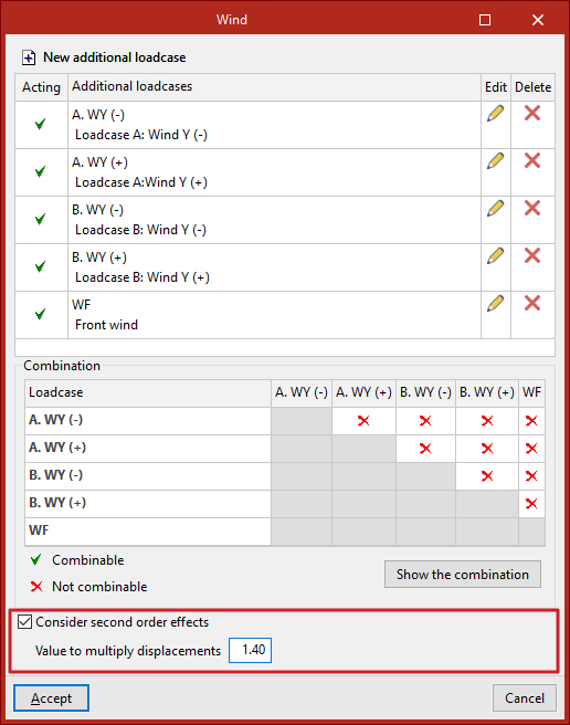
If several additional loadcases are added, the program displays a "Combination" table between different loadcases where their "Combinable" or "Non-combinable" status is indicated. The "Show combination" button is used to list the "Combinatorics" obtained after manipulation of the table.
| Note: |
|---|
| The number of load layouts or combinable loadcases should not be increased indiscriminately due to the large number of automatic combinations that can be generated. |
Considering second-order effects
For additional horizontal loads such as in the wind or earthquake loads, the program can "Consider second order effects" by activating the corresponding check box and typing in a "Value for multiplying displacements" to be estimated by the user.
| Note: |
|---|
| The displacement amplification value for concrete elements can be estimated at 1/0.7=1.43, corresponding to a stiffness reduction of 30 %, according to the Brazilian standard NBR 6118. As a higher value, 1/0.5=2 can be estimated, corresponding to a stiffness reduction of 50 %, according to the CEB-FIP 1990 Model Code. |
Options for configuring element references
From the "Numbering" group of the "Job" tab the element references (nodes, bars, parts and shells) can be configured according to the user's preference or to reset the numbering according to the current model data:

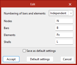
Edit numbering
The "Edit" tool can be used to configure the numbering of the elements of the structure.
The "Numbering of bars and parts" drop-down list can set the numbering of bars and parts in two alternative ways:
- By nodes
The program automatically assigns the numbering of the bars and parts based on the numbering of the end nodes (e.g. N1/N2, N2/N3, N3/N4, etc.). - Independent
The program automatically assigns the numbering to the bars and pieces independently, regardless of the numbering of the end nodes (e.g. B1, B2, B3, etc.).
From this dialogue box, it is also possible to define the prefixes for the numbering of "Nodes", "Bars", "Parts" and "Shells", by default N, B, Pz and L. The field can be left empty if you do not wish to define a prefix.
| More information: |
|---|
| References to items already entered are maintained when deleting or adding new items. |
Reset numbering
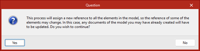
The "Reset" tool can be used to reset the numbering to the current model data. This can be useful if elements have been deleted and no jumps in the numbering are desired. The program will launch a warning informing you of the process to be carried out to confirm.
Assigning new references to elements may require revision and updating of documents already obtained from the model.