"Trim section" option
The "Trim section" option is used to trim the selected section based on the dimensions entered. The type of trim can also be defined: straight, with a radius or with a drill hole.

Inserting and defining section trims
To insert the trimming, click on the "Trim section" option in the top toolbar.
Then, in the first drop-down menu, select the "Section" to be trimmed from those available.
Next, indicate the "Position" of the trimming, which can be at the "Top" or "Bottom" of the section.
Under "Type of trim", specify whether it is "Straight", "With chord radius", or "With drill hole":
- In all three cases, the “X” and “Y” dimensions of the cut-out must be specified in the units shown.
- When using cut-outs "With chord radius" or "With hole", the "Chord radius" or the "Hole diameter" is also specified, respectively.
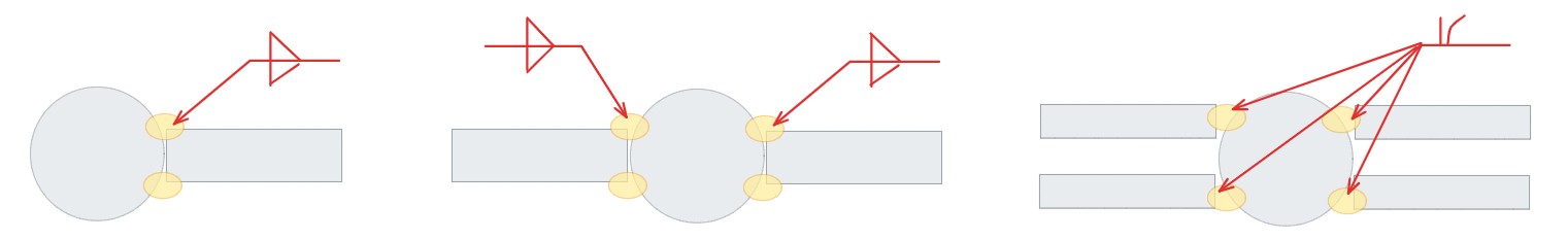
- The image below is provided as an aid to understand the reference system for these dimensions. All of them refer to the envelope of the section, that is, its original geometry prior to the application of adjustments.
- The "Display options" can be used to make the position of the envelope visible in the joint view. To do this, the "Sections" are shown as transparent by clicking in the cell of the "Drawing" column, and the display of the "Envelope" is activated on the right. After clicking "Accept", the envelopes of the sections are displayed in grey.
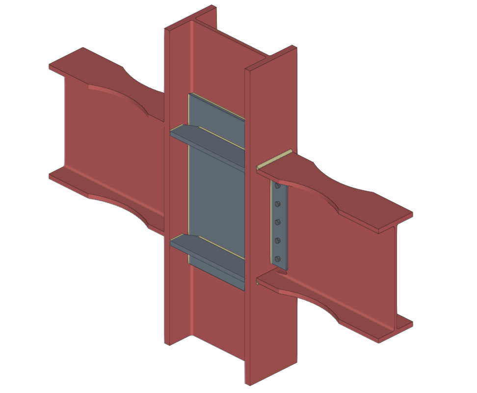
Example
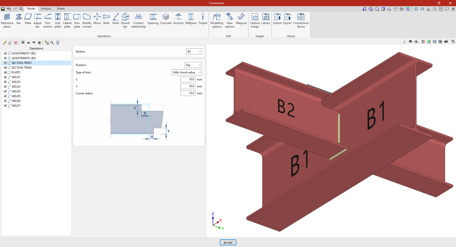
In the example shown here, corresponding to a connection between beams, adjustments have already been made to the sections of beams B2 and B3, which are perpendicular to beam B1.
Next, the necessary trims are made to avoid clashes identified by the program between the beam plates:
- In the first trim, one of the secondary beams, B2, is selected. The cut position is "Top", as the cut is to be made at the top of the section. A "Radius match" cut is used, with an X dimension of 10 millimetres, a Y dimension of 30 millimetres and a radius of 10 millimetres.
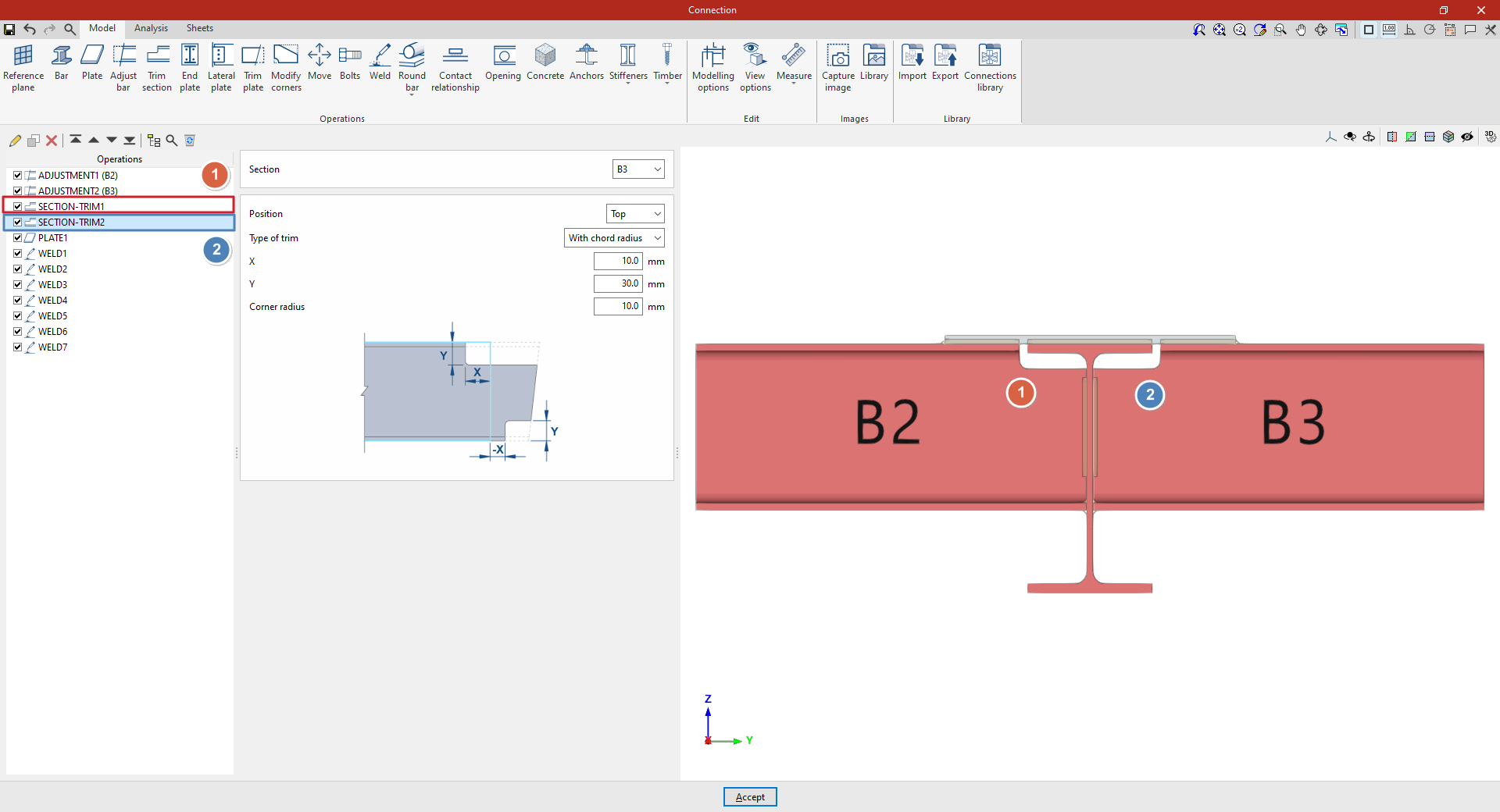
- To define the second trim, apply this operation to the other beam by selecting the first one and using the “Copy” option available at the top of the table on the left. In this new operation, in the "Section", beam B3 is selected, with the rest of the parameters remaining the same.
From this point onwards, the rest of the operations necessary to complete the joint model must be added before the "Analysis" of the connection can be performed.
Options for positioning bolts and anchors
StruBIM Steel and CYPE Connect offer various options for placing bolts and anchors. These options are available when using the "Bolt" or "Anchors" operations, located in the "Operations" group of the "Model" tab in the editing window for each connection. The available options are as follows.
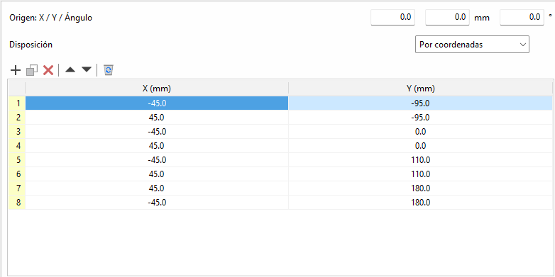
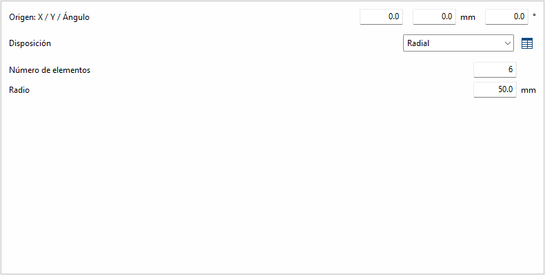
By coordinates
Elements can be placed by directly indicating their X and Y coordinates in a table. This is the ideal option for cases where a more precise location of each element is required.
The origin of the local reference system for openings, bolts and anchors can be edited. Above the coordinate editing table is the "Origin" section with the editing of the "X" and "Y" displacements and the rotation angle. These displacements are applied to the group of elements contained in the table. In bolts, the original reference system corresponds to that of the first plate. In anchors and openings, it corresponds to that of the selected plate.
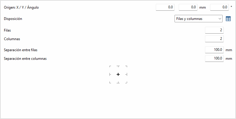
Rows and columns
Distributes the elements regularly in rows and columns, defining the number of elements per row and column and the spacing between them. This is a practical option for homogeneous configurations.
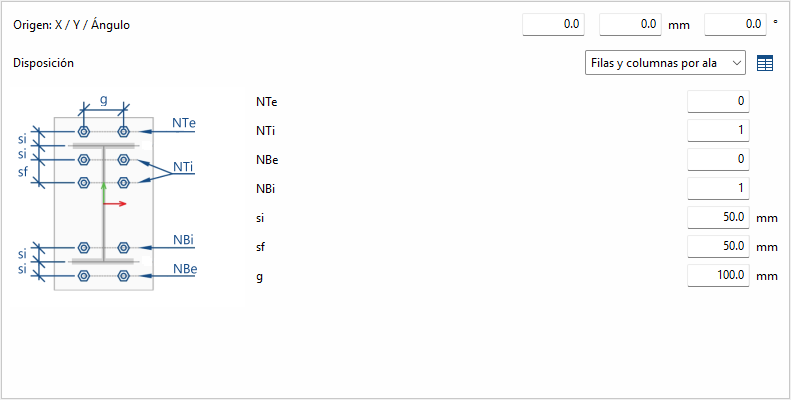
Rows and columns per flange
Typical distribution of end plates in I-sections. In the "End plate" operation, the edge of the bar that is joined to the plate is known, so it doesn't need to be inserted. In other operations, the edge between flange centres is requested.
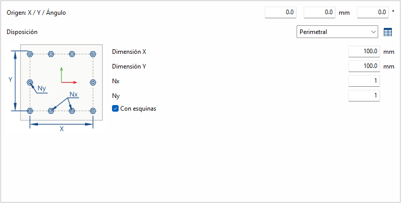
Perimeter
Given the dimensions "X" and "Y" of a rectangle, it allows the elements to be placed optionally in the corners, and the rest of the elements are distributed along each side according to the number indicated.
Radial
Given a radius and the number of elements, these are placed radially.
| Best practice: |
|---|
| Next to each option, except for "by coordinates", there is a button to convert the layout into a list of coordinates, allowing you to easily make changes if desired. |
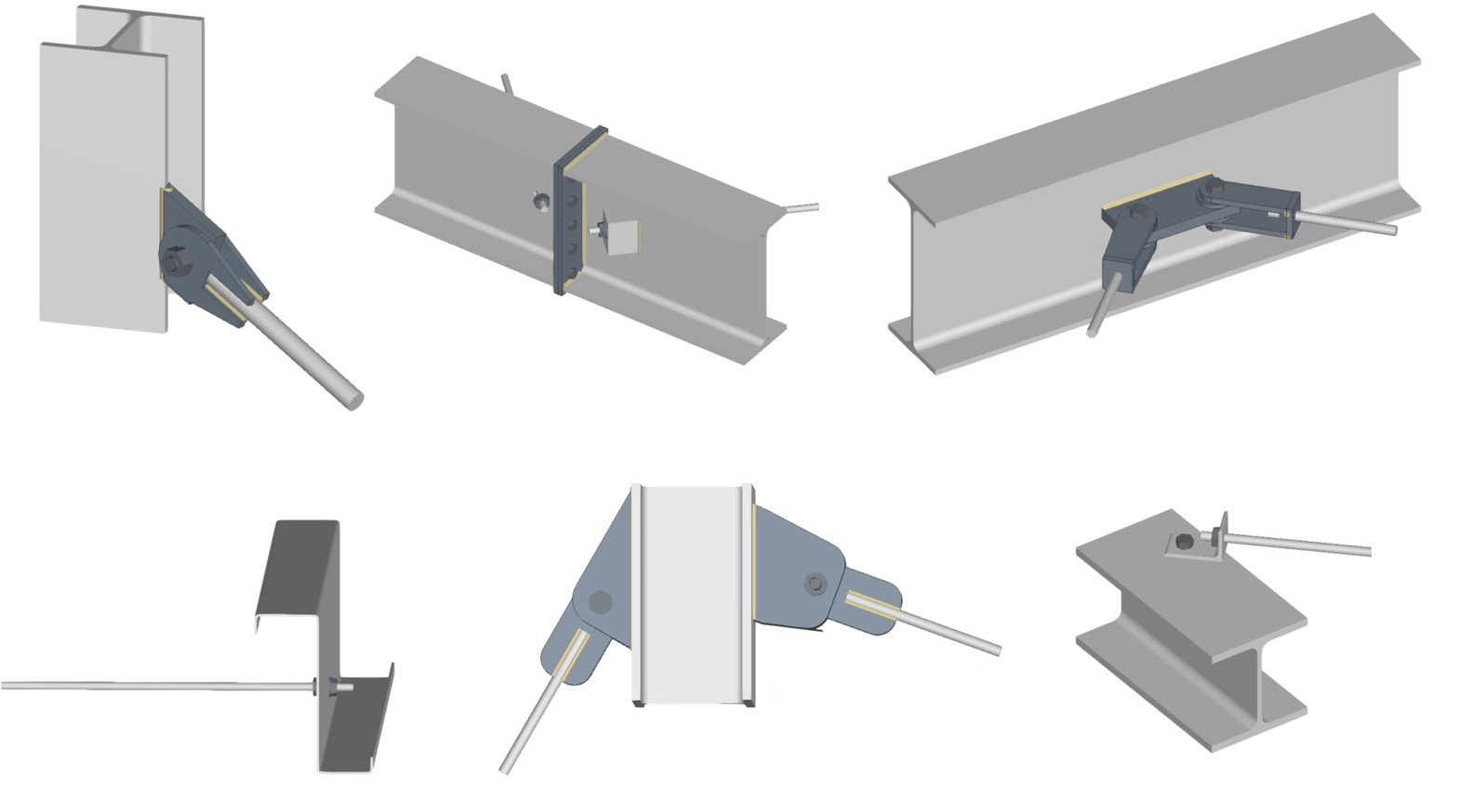
Connection with solid round bars
Connections with solid round bars can be used in CYPE Connect and StruBIM Steel. Unlike other bars, these bars are discretised with a linear element. Although the implementation focuses on solid round bars, if a solid square bar is used, it will be treated in the same way.
To do this, within the "Operations" group of the "Model" tab in the editing window of each connection, use the "Solid round" group, which displays a menu with the different operations available.
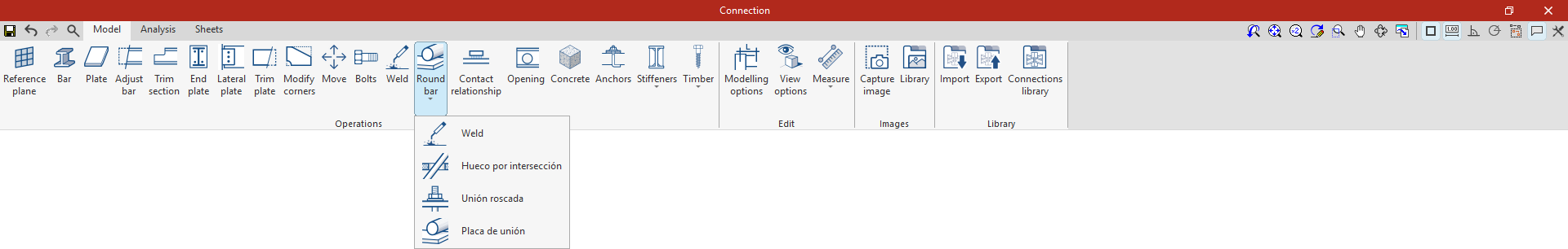
Welding
This operation allows you to weld a solid bar to a plate whose surface is parallel to the bar's directrix.
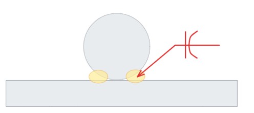
Welding can be done in two ways:
- Between the bar and the surface of the plate
Welding is allowed on one side or both sides of the bar. The weld will be of the flare-bevel weld type. - Between the bar and the edge of the plate
Different types of welding may be used: flared bevel, angle or edge preparation. The most suitable choice will depend on the thickness of the plate and the diameter of the bar.
Hole at intersection
In this operation, a bar and a plate are selected, and a hole is created in the plate at the point of intersection with the bar. The hole is shaped like an elongated drill hole.
Threaded connection
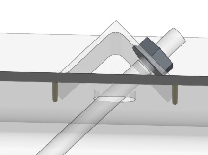
This operation allows the end of a round bar to be joined to a plate using nuts. To do this, the bar and the plate to which it is joined are selected.
There are several nut arrangements, and it is necessary to define the length of the tie rod from the last nut, as well as the clearance of the hole. In addition, the reference of the nut and the washer are requested. If the corresponding box is checked, it is possible to manually define the text string; by default, this is generated automatically based on the diameter of the bar. It should be noted that it is not linked to the references in the bolt libraries.
The bar does not have to be perpendicular to the plate. In these cases, users can specify the type of washer or additional device to be placed (see example). This case is not currently represented in the 3D view.
Connecting plate
This operation can place plates using a solid round bar as a reference. In addition to facilitating its positioning, it allows you to generate slots in the plate to fit the bar and apply welds.
| Note: |
|---|
| Bars are linear elements, so their designs and checks are carried out during the overall design of the structure, in programs such as CYPECAD or CYPE 3D. From StruBIM Steel and CYPE Connect, what is analysed and verified is the connection of the bar with the rest of the elements (plates, bolts, welds, etc.). |
Prequalified connections
Prequalified connections can be used in CYPE Connect and StruBIM Steel. To do this, within the "Operations" group of the "Model" tab in the editing window of each connection, the "Prequalified connections" operation is used, which allows a menu to be displayed with the different types available.

Definition and application
A prequalified connection is a structural connection whose geometry, construction detail and behaviour have been previously verified by testing and analysis, and which complies with the criteria set out in specific standards, especially in the field of earthquake-resistant construction.
Prequalified connections are applied and required in structures where the seismic-resisting system consists of moment frames (without bracing), particularly in the case of special frames (SMF) or intermediate frames (IMF), as defined in AISC 341.
Related regulations
In the program, the "Prequalified connections" operation only appears in projects that have one of the following steel codes selected:
- United States: AISC 360-22 (LRFD)
- Colombia: NSR-10
- Mexico: NTC-2023
Prequalified connection types available
The types of prequalified connections implemented are as follows:
- RBS (Reduced Beam Section)
- BEEP (Bolted Extended End Plate)
Includes types 4E (four-bolt unstiffened), 4ES (four-bolt stiffened) and 8ES (eight-bolt stiffened). - BFP (Bolted Flange Plate)
- WUF-W (Welded Unreinforced Flange-Welded Web)
The program can be used to define in detail the components of each prequalified connection in the operation's editing panel.
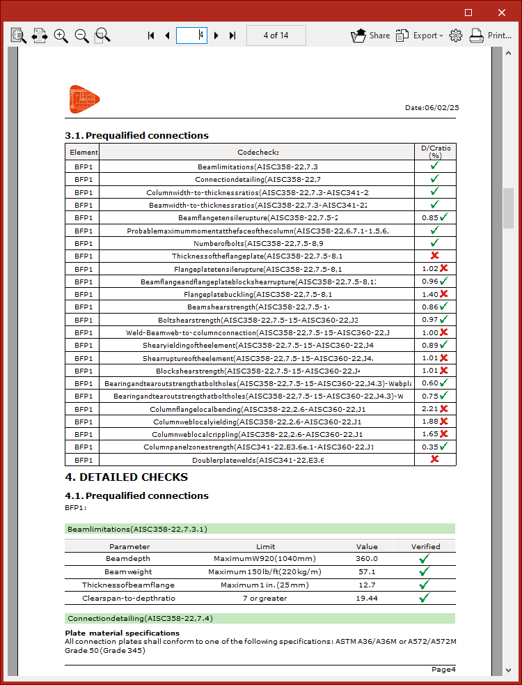
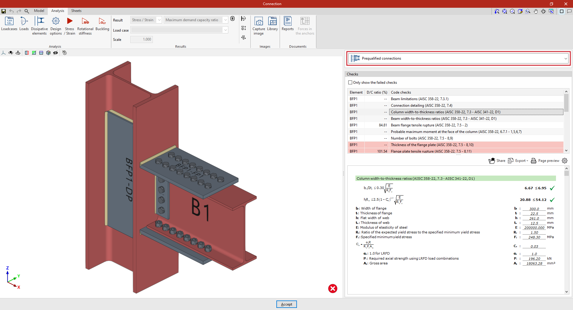
Checks on prequalified connections
In addition to the other checks carried out on the connection, the program carries out the specific checks defined in the AISC 341 and AISC 358 standards for prequalified connections.
These checks can be displayed on screen by selecting the "Prequalified connections" option, available in the corresponding drop-down in the "Analysis" tab of the connection editing window.
| Note: |
|---|
| Other operations can be defined at the same node where a prequalified connection has been inserted. This way, a different type of seismic-resisting system could be defined in each direction of the structure. In the direction where no pre-qualified connections are applied, the program will perform the usual checks after the finite element design. However, the prequalified connection check will not consider the effects of additional operations, displaying a warning in this case. |
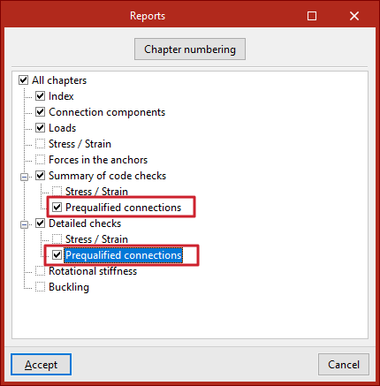
Prequalified connection check reports
The documents provided by the program include summarised and detailed reports of the checks carried out on the defined prequalified connections.
To obtain this, the corresponding sections of the report must be activated.