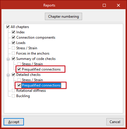
Options available when defining connections
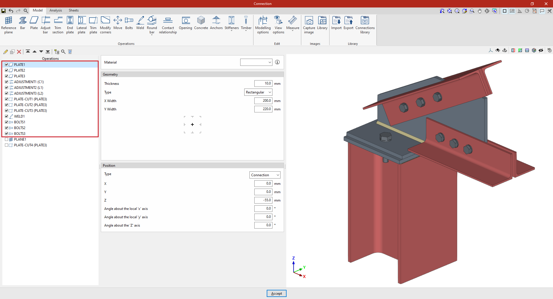
In the “Model” tab of the connection editing window, you must specify the “Operations” required to define the connection using the tools in the relevant panel. The available operations are as follows:
- Timber:
- Prequalified connections (only in the available standards)
To open the edit window for a “Connection”:
- In CYPE Connect, once the node has been created, select it from the table on the left-hand side of the interface and edit the “Connection” by clicking on the corresponding button at the top.
- In StruBIM Steel, select the "Edit" option for the connection in the "Model" tab (which was previously created using the "Connection" option).
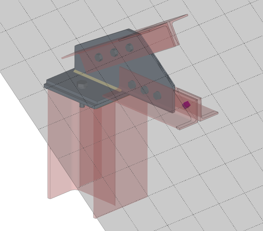
"Reference plane" function
The "Reference plane" function allows you to insert auxiliary reference planes when modelling connections; these can be used to create cuts in sections and plates, to adjust the extension or reduction of these planes, or as a reference when adding plates.

| Example (original situation): |
|---|
| In the example shown here, plates, bolts and welds have been added, and adjustments have been made to the connection sections and cut-outs in the plates. To complete the connection, a reference plane can be added, which can then be used to create the final cut-out on one of the plates in the model. |
Inserting the reference plane
To insert a reference plane, click on the “Reference plane” option in the top toolbar.
When you do this, the selected reference plane is displayed as a grey surface in the 3D view on the right.
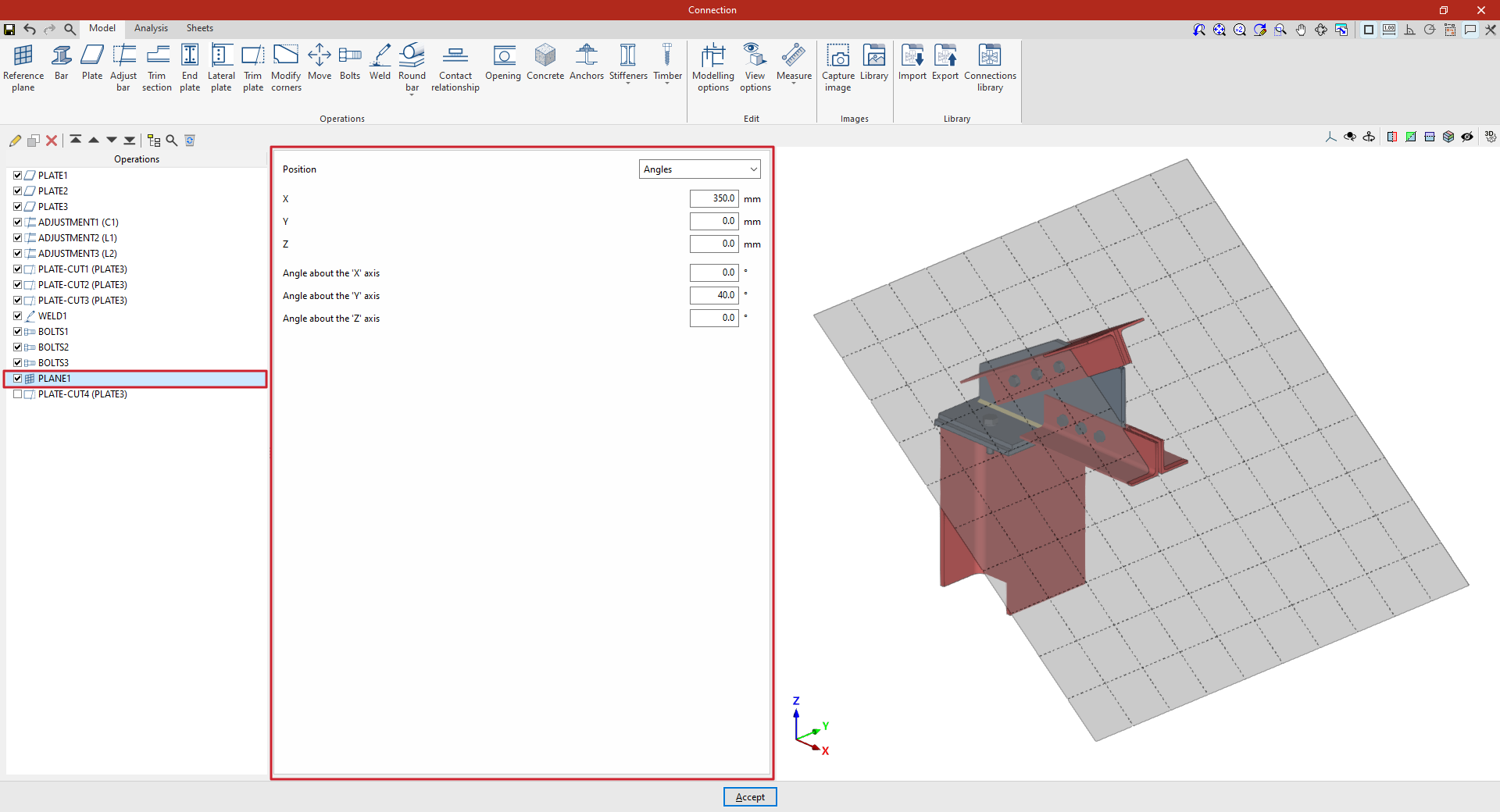
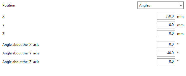
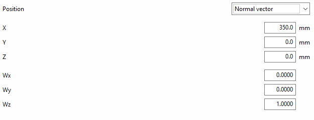
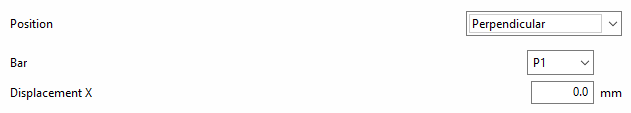
You can adjust the plane’s position using the options in the central panel. The “Position” can be set in the following ways, selected from the drop-down menu:
- By "Angles";
- Using a "Normal vector" to its surface;
- "Perpendicular" to a bar;
- "Defined by two bars" that make up the plane;
- On the "Bisector" between two bars;
- At the "Intersection" between two bars;
- At the intersection between a bar and the envelope of another (by selecting the "Intersection (Envelope)" option);
- Or perpendicular to the "Edge" of a plate.
| Example (continued): |
|---|
| Once the reference plane has been created, it can be used in other options such as “Trim section” and “Trim plate”, or to define the position of a “Slab” or a “Concrete” element. For example, you can define the “Position” using “Angles” and then add a slab trim that uses the “Reference plane” you have entered. This completes the connection model. From here, you can perform the “Analysis” of the connection in the tab provided for this purpose. |
Cutting a plate using a reference plane
The following options allow you to define planes in any position:
Angle-based reference plane
If “Position” is defined by “Angles”, you must first enter the “X”, “Y” and “Z” coordinates of a point on the plane.
The plane is then rotated by entering the “Angle about the ‘X’ axis” and the “Angle about the ‘Y’ axis”. These values refer to the global axes of the assembly’s coordinate system.
Reference plane using a normal vector
If the “Position” of the plane is defined by a“Normal vector” to its surface, the “X”, “Y” and “Z” coordinates of a point on the plane are specified first.
Next, the components “Wx”, “Wy” and “Wz” of the normal vector are written.
The following options allow the plane’s position to be referenced to other elements, meaning that if the dimensions or positions of the bars change, the plane’s position will also change. This is particularly useful when combined with the use of the connection library:
Reference plane perpendicular to a bar
To define the “Position”, you can specify that the reference plane is “Perpendicular” to a bar.
In this case, select “Bar” from the relevant drop-down menu.
You can then apply an “X displacement” to the plane along the section’s local X-axis; this can be either positive or negative.
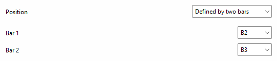
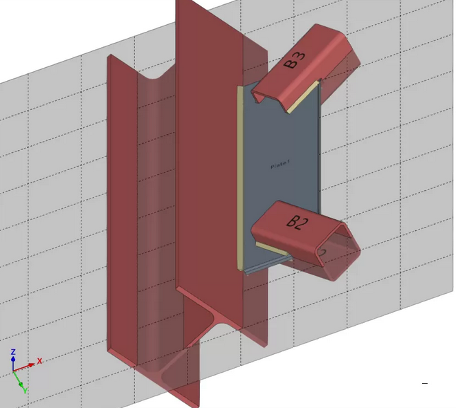
Reference plane based on two bars
To define the “Position”, it can be stated that the reference plane is established “Defined by two bars”.
In this case, select “Bar 1” and “Bar 2” from the relevant drop-down menus.
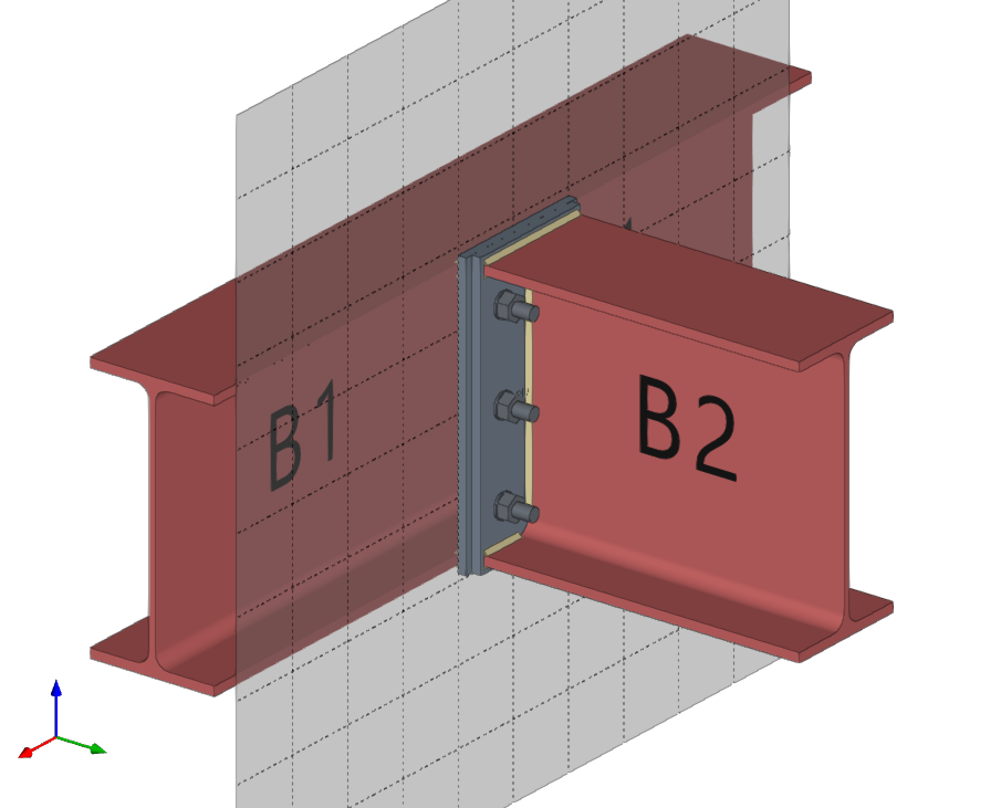
With this option, if the two selected bars lie in the same plane, the reference plane will be created at the point where their two local X-axes intersect. When the bars do not lie in the same plane, the reference plane will be created at the midpoint of their origins.
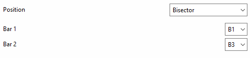
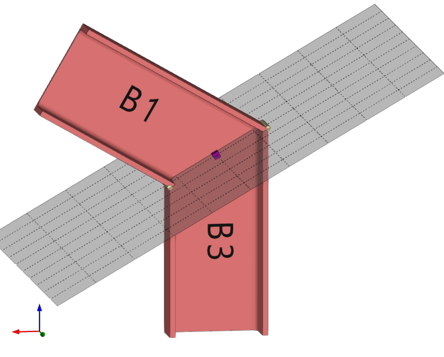
Reference plane on the bisector of two bars
To define the “Position”, one can state that the reference plane lies on the “Bisector” of two bars.
In this case, select “Bar 1” and “Bar 2” from the relevant drop-down menus.
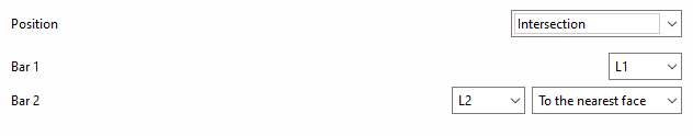
Reference plane at the intersection between a bar and one of the plates of another bar
To define the “Position”, it can be stated that the reference plane lies at the “Intersection” between a bar and one of the plates of another bar.
In this case, select “Bar 1” and “Bar 2” from the relevant drop-down menus.
You must specify the plate or part of the second bar with which you wish to obtain the intersection, for example, "To the nearest face", "To the furthest face", the "Flange" or the "Web" of an L-shaped section.
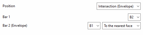
Reference plane at the intersection of one bar and the envelope of another bar
To define the “Position”, you can specify that the reference plane lies at the intersection of one bar and the envelope of another bar (using the “Intersection (Envelope)” option).
In this case, select “Bar 1” from the first drop-down menu and the bar for which you wish to analyse the envelope from the second drop-down menu (“Bar 2 (Envelope)”).
You must specify the face of the envelope with which you wish to obtain the intersection, whether it be "To the nearest face", "To the furthest face", the top face ("Top face"), the bottom face ("Bottom face"), the left face ("Left face") or the right face ("Right face").
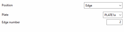
Reference plane at the edge of a plate
To define the “Position”, one can specify that the reference plane lies on the “Edge” of a plate.
In this case, select “Plate” from the first drop-down menu, and enter the “Edge number” of the plate where you wish to place the drawing in the corresponding field.
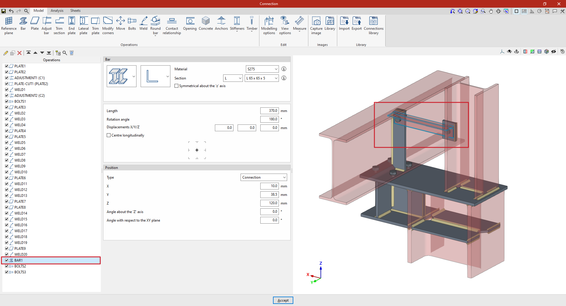
"Bar" function
The "Bar" function in connection modelling allows you to add additional bars to the connection that have not been previously included in the node’s section definition, enabling you to simulate sagging, support elements, reinforcement brackets, etc.

Inserting the additional bar
To insert the additional bar, click on the “Bar” option in the top toolbar.
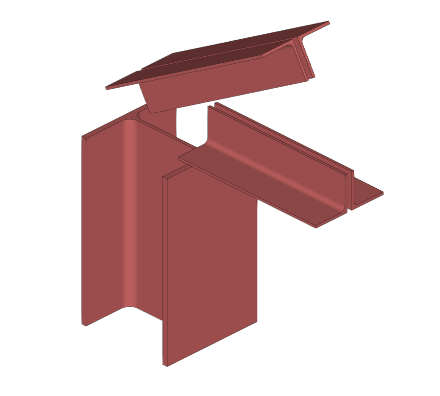
| Example: |
|---|
| In the example shown here, plates, bolts and welds have been added, and adjustment operations have been carried out on the connection sections. To complete the connection, an auxiliary bar is inserted between the plates welded to column C2 and beam B1. This bar was not previously included in the definition of the connection sections. |
Model of the connection before and after the insertion of the additional bar
Selection of material and cross-section for the additional bar
In the “Beam” section, use the drop-down menus to select whether the section is made of rolled steel, formed steel, metal tubing or timber, and then select the type of cross-section:
- In the case of rolled steel bars, these may be rolled I, simple U, angle, T section, round bars or square bars
- In the case of shaped steel bars, these may be U-shaped, C-shaped, simple Z-shaped, stiffened Z-shaped, L-shaped or stiffened L-shaped
- In the case of steel hollow sections, these may be rectangular or circular hollow sections
- And in the case of wooden bars, the cross-section is solid rectangle
On the right, select the “Material” from the drop-down menu.
Next, select the "Section" from the drop-down menus below, choosing a specific section from the available series and a particular section within that series.
The information buttons on the right allow you to view the material properties and the geometric properties of the section.
On the right-hand side, you can specify the “Resistance depending on the thickness”.
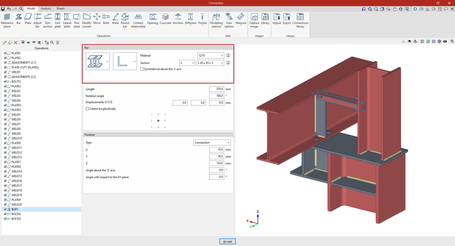
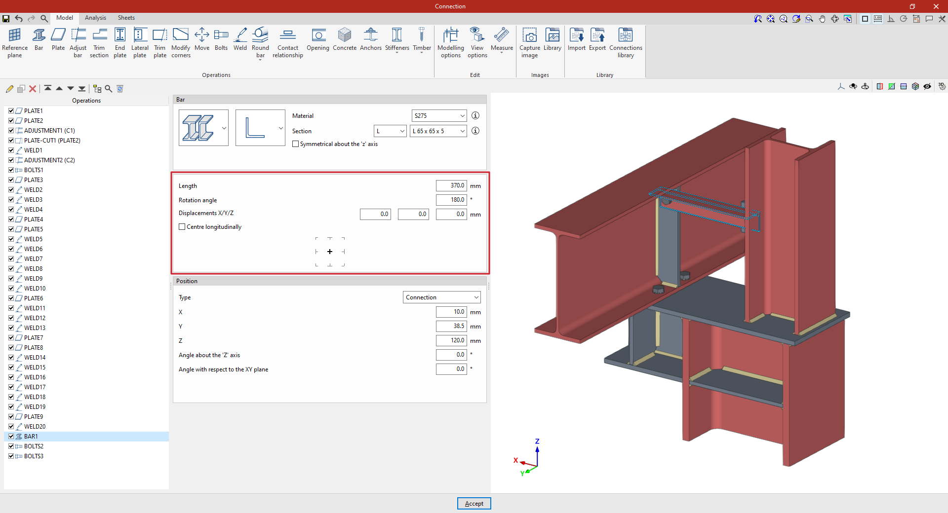
Determining the length and positioning of the additional bar
Next, enter the “Length” of the section.
The following parameters allow you to adjust the bar’s layout. The “Rotation angle” and the “X displacement”, “Y displacement” and “Z offset” refer to the section’s local coordinate system. For example, you can enter a value of 180 degrees, with no offsets, to rotate the section about its axis. These offsets modify the bar’s position relative to its default position.
If the "Centre longitudinally" checkbox is ticked, the section will be positioned so that its longitudinal centre coincides with the reference point defined in the following section. If it remains unticked, the end of the section will be aligned with that point.
Further down, you can select the reference point for the additional bar in the diagram: either the axis of the section, the centre of one of its faces, or one of its corners.
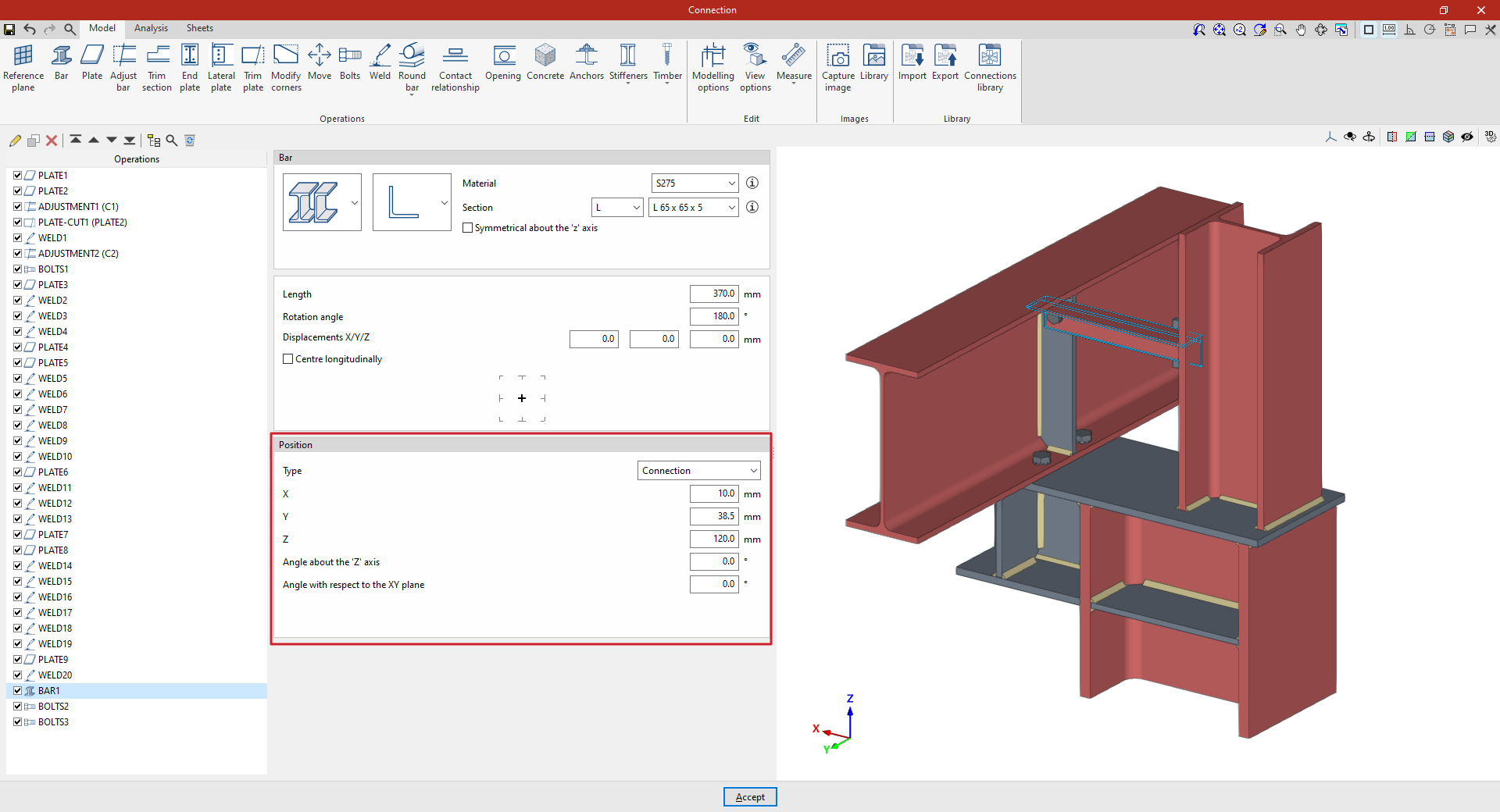
Adjusting the position of the additional bar
The “Position” section defines the reference point for the bar’s position. This can be one of the following, depending on the selection made in the “Type” drop-down menu:
- If "Connection" is selected, the additional bar will be positioned using the centre of the connection as a reference. The "X", "Y" and "Z" distances from the section's local coordinate origin to the centre of the connection are then specified.
Furthermore, the “Angle about the Z-axis” or vertical axis of the connection allows a rotation in plan view, and the “Angle with respect to the XY plane” applies a rotation in the vertical plane containing the section. - If you select "In the direction of a bar", the additional bar you enter will be positioned along the direction of the selected bar. First, select an existing "Bar".
From here, you can enter "X/Y/Z displacements" in the local coordinates of that beam, as well as enter the "Angle around the local 'y' axis" and the "Angle around the local 'z' axis" of the selected beam to adjust the orientation of the additional beam relative to it.
At the bottom, you can also select the reference point for the additional beam in the diagram, whether this is the centreline of the section, the centre of one of its faces, or one of its corners.
From this point onwards, you must add the remaining operations required to complete the connection model before you can perform the “Analysis” for it in the relevant tab.
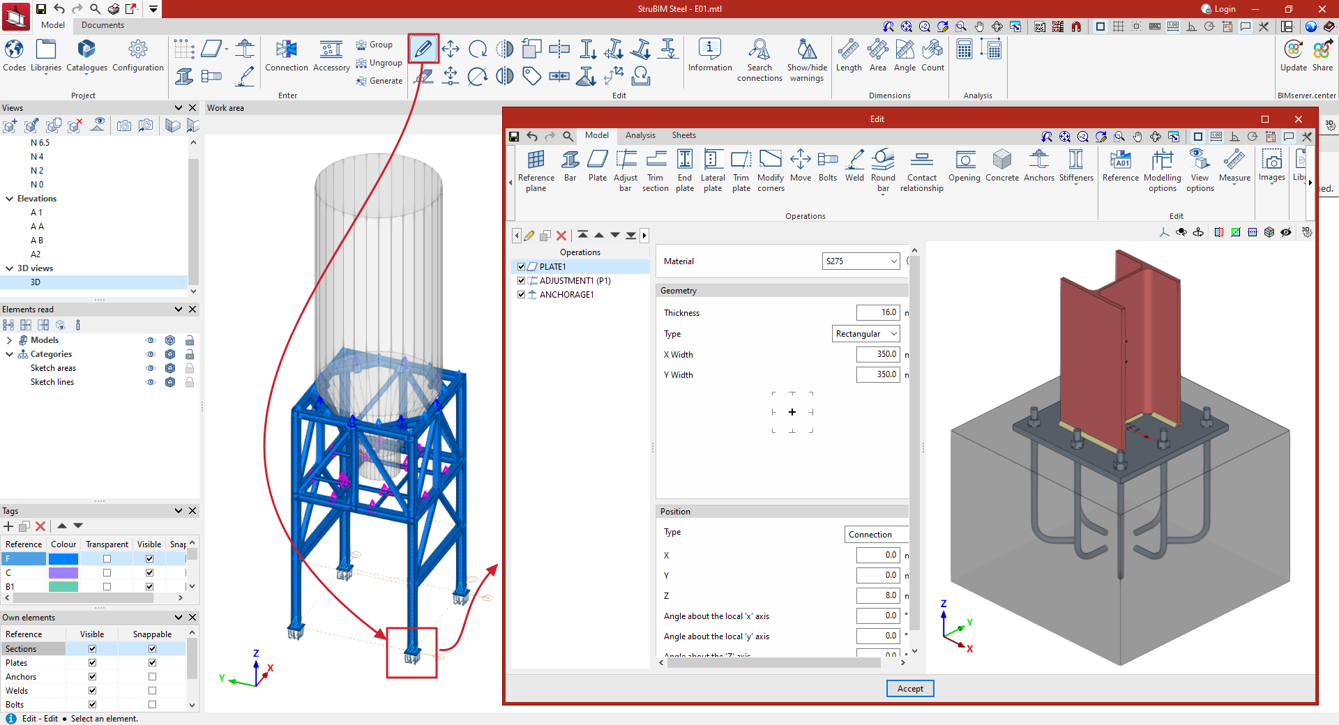
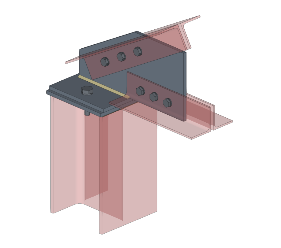
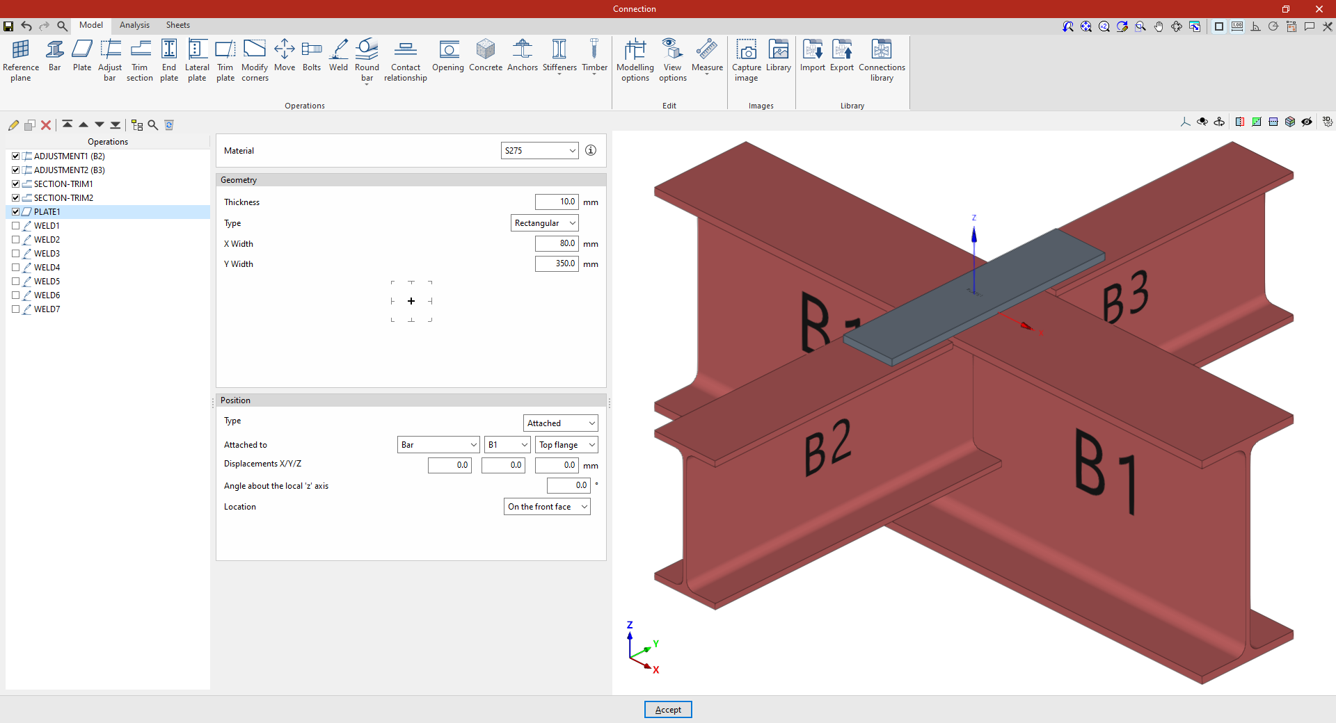
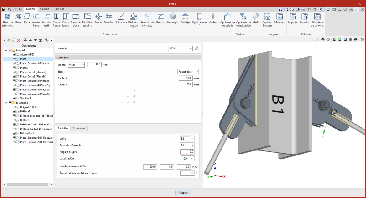
"Plate" function
The "Plate" tool allows you to create rectangular and polygonal plates and insert them into the connection model. Polygonal plates can be defined using coordinates, and you can copy and paste tables directly from spreadsheets.

Inserting the plate
To insert a plate, click on the “Plate” option in the top toolbar.
| Note: |
|---|
| In the example shown here, adjustment operations have already been carried out on the sections to modify their geometry. Next, three plates are added to complete the connection between the sections. |
Inserting plates to resolve the intersection between different sections
Selecting plate material
First, select the “Material” for the plate from the drop-down menu. If you click on the information button on the right, you can view its properties.

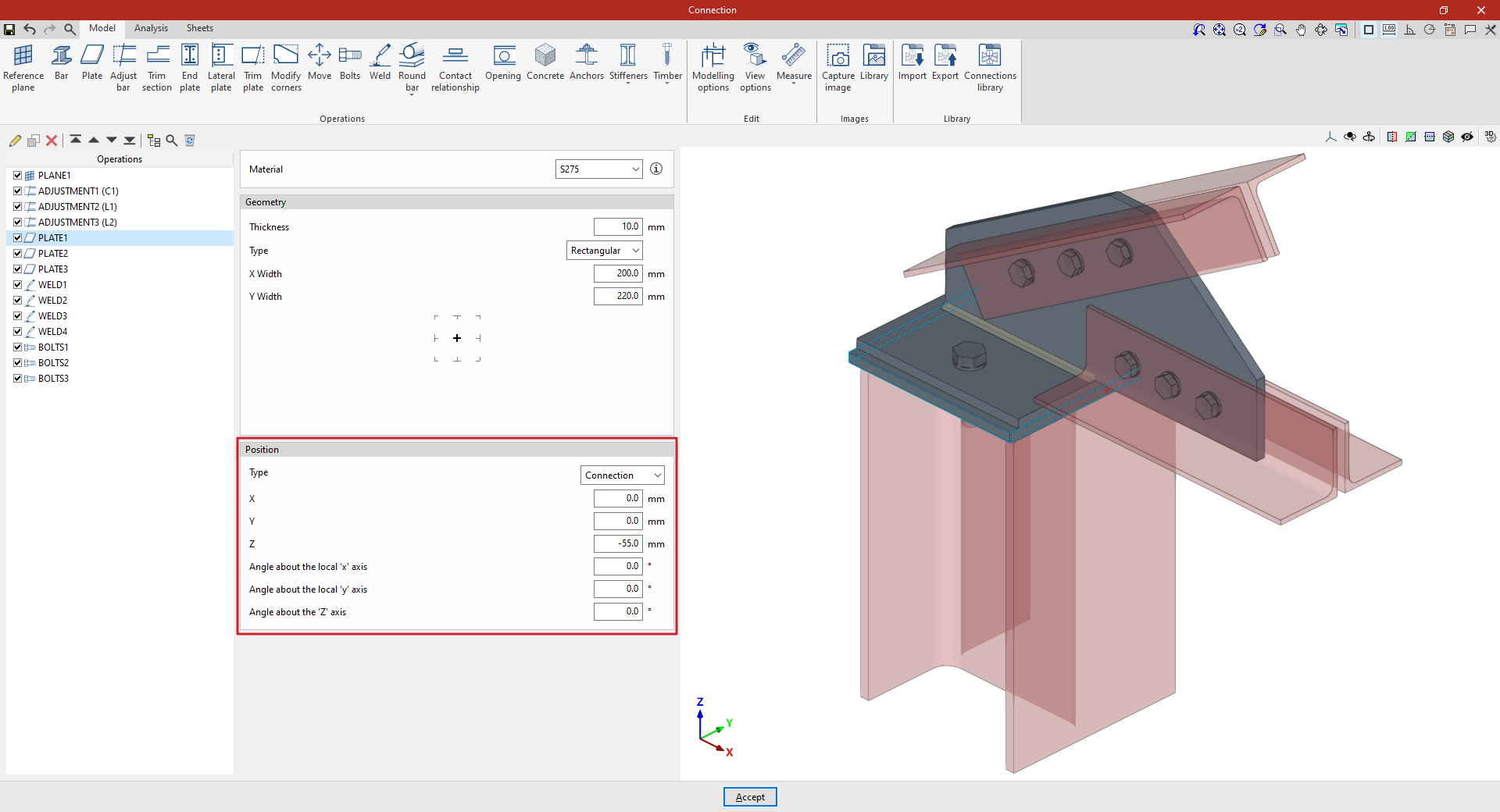
Defining the plate geometry
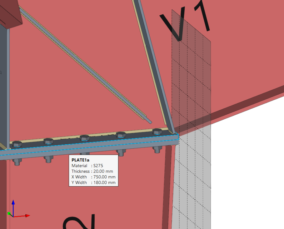
The following section defines the “Geometry” of the plate. Enter the “Thickness” and select the “Type” of plate from the drop-down menu: “Rectangular”, “Circular” or “Polygonal”.
Rectangular plates
If “Rectangular” is selected, you must specify the “Width X” and “Width Y”.
Circular plates
If you select “Circular”, simply enter its “Diameter”.
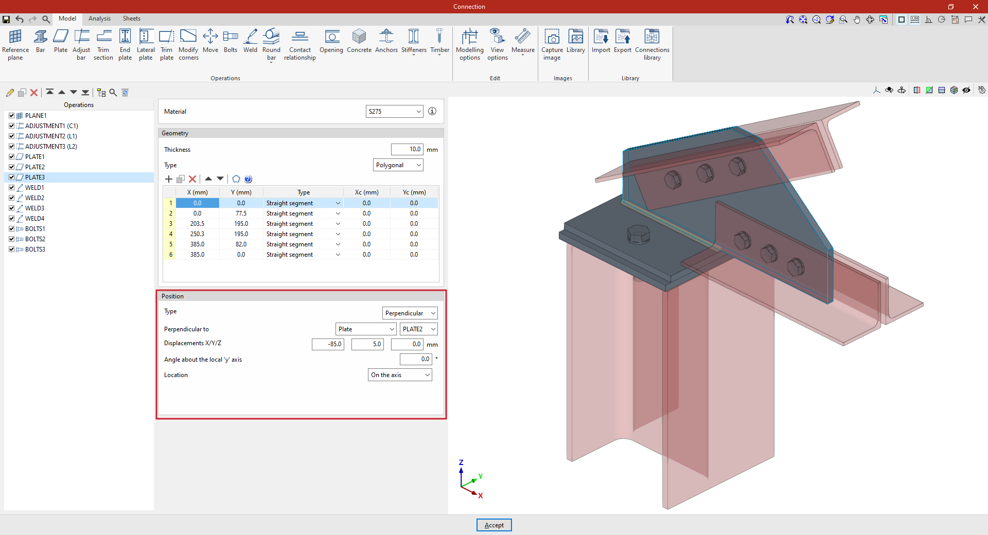
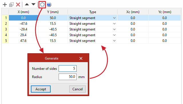
Polygonal plates
If “Polygonal” is selected, a table appears in which the geometry of the plate is defined by entering its vertices using coordinates:
- The options in the top bar allow you to "Add", "Copy", "Delete" and reorder vertices in the list.
- If it is a straight section, select "Straight span" in the "Type" column and define the "X" and "Y" coordinates of the starting vertex. The section will extend to the "X" and "Y" coordinates of the next vertex.
- If the section is curved, select "Curved span" in the "Type" column and define the coordinates of the centre of the arc, "Xc" and "Yc". The section will extend from the "X" and "Y" coordinates defined for it to the "X" and "Y" coordinates of the next vertex.
- The program also features a "Generate" tool at the top of the list, which allows you to automatically generate vertices for polygonal plates with straight sections by entering the "Number of sides" and the "Radius" of the circle circumscribed around the plate’s vertices. Using this tool will clear any data previously entered in the list.
- To make it easier to enter this data, the program displays a "Help" image when you click on the relevant button at the top of the list.
Defining the plate position
Finally, the “Position” of the plate is defined. The position of the plate may be relative to the centre of the “Connection”, or the plate may be “Attached” to or “Perpendicular” to another plate, another beam or a reference plane.
The inserted plate can be viewed in the 3D view on the right.
Plate positioned relative to the centre of the connection
In the “Type” drop-down menu, select “Connection” to define the position of the plate by entering the “X”, “Y” and “Z” coordinates relative to the centre of the connection.
If the plate needs to be rotated, you can enter the “Angle about the local ‘x’ axis”, the “Angle about the local ‘y’ axis” and the “Angle around the ‘Z’ axis”.
Panel attached to another element
To define the “Position”, select the “Attached” “Type”. This allows you to specify that the plate is “Attached to” another “Plate”, a “Section” or a “Reference plane”.
If required, you can enter an “X displacement”, a “Y displacement” and a “Z displacement”, as well as an “Angle around the local ‘z’ axis”, which allows you to adjust the position of the plate.
Finally, the “Location” of the plate is specified, which may be “On the front face”, “On the back face” or “On both faces”; in the latter case, two plates are produced.

A plate perpendicular to another component
If you select the “Perpendicular” option under “Position”, you can specify that the plate is “Perpendicular to” another “Plate”, a “Section” or a “Reference plane”, which can be selected from the drop-down menu on the right.
Next, enter the “X/Y/Z displacements”, which allow you to adjust the position of the plate in space. You can also enter an “Angle about the local ‘z’ axis”.
The “Location” of the plate is also indicated; this may be “On the front face”, “On the back face” or “On both faces”, in which case two plates are generated.
From this point onwards, the remaining operations required to complete the connection model—such as welds and bolts—must be added before the connection can be analysed.
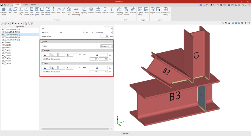
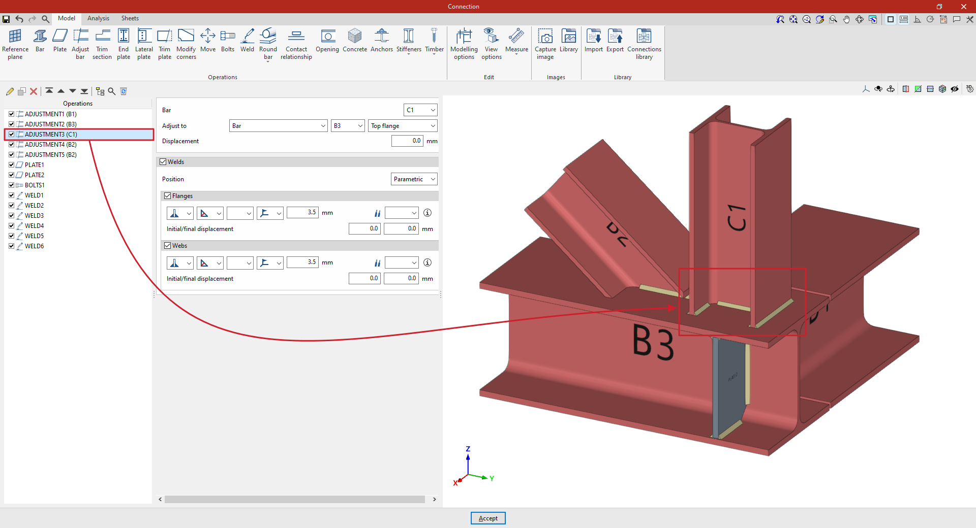
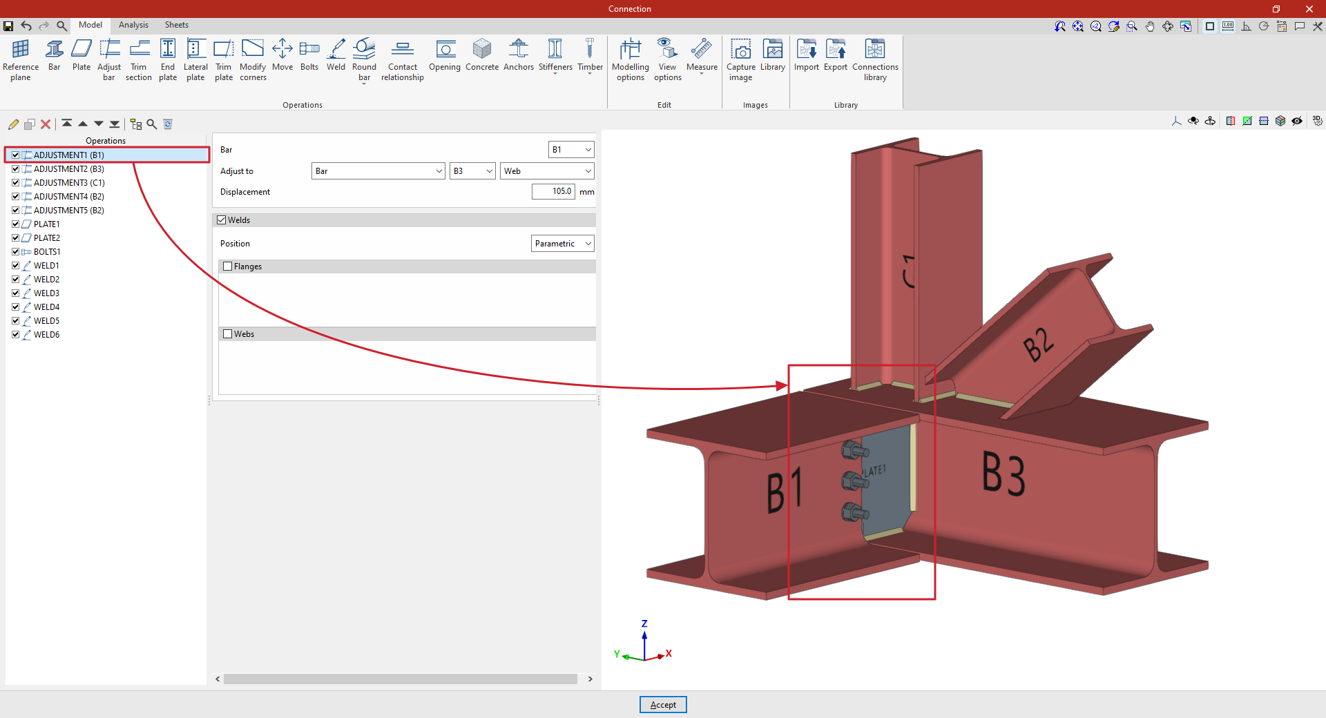
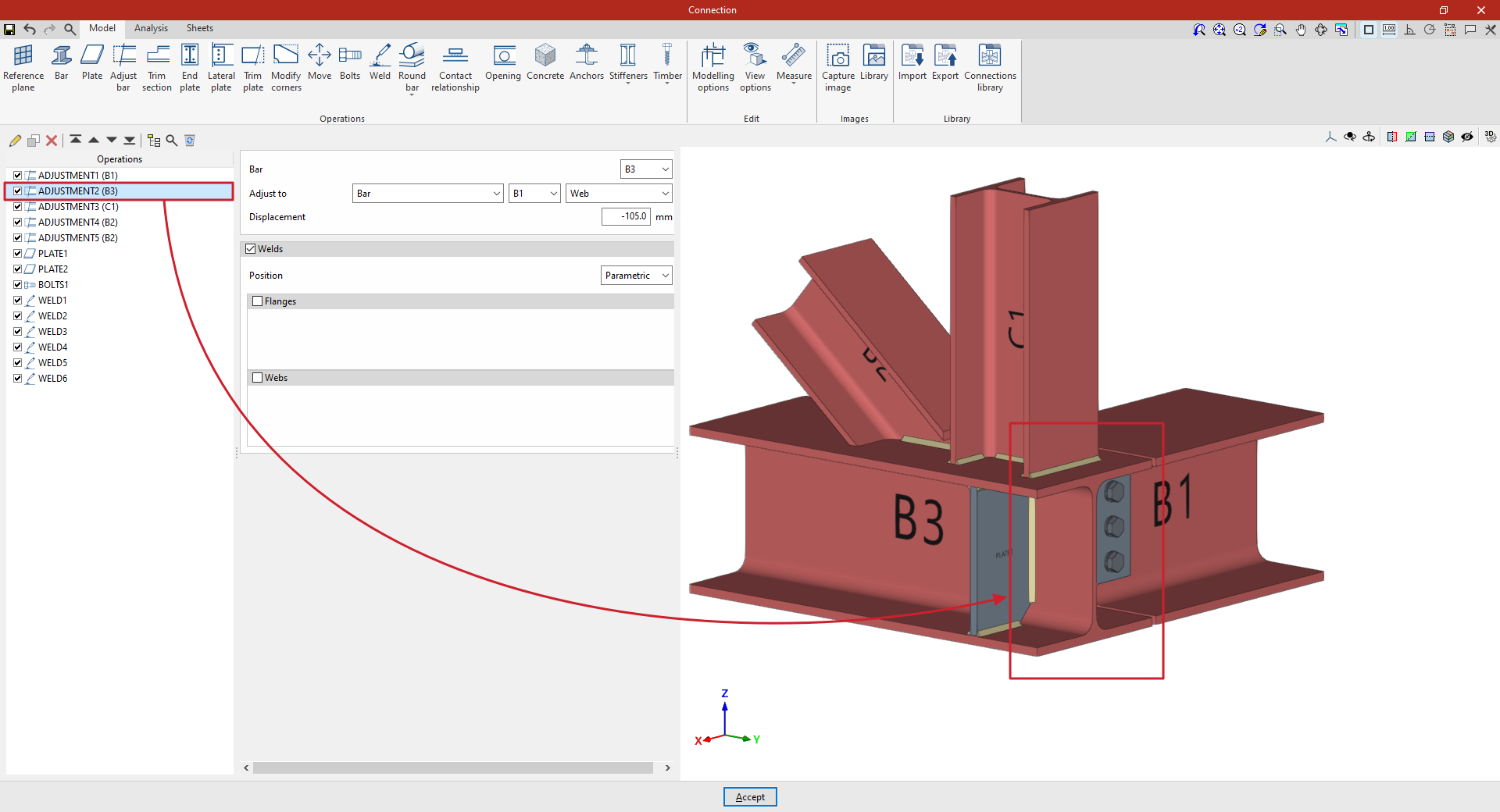
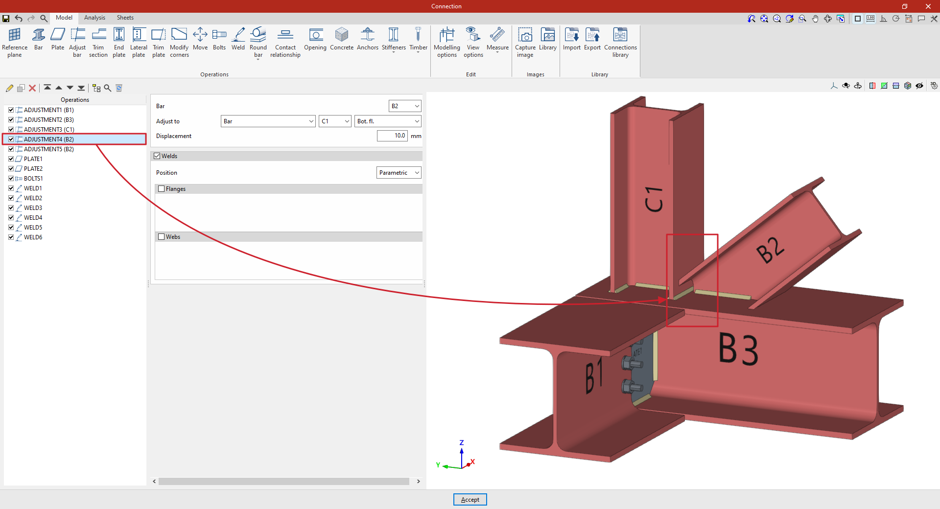
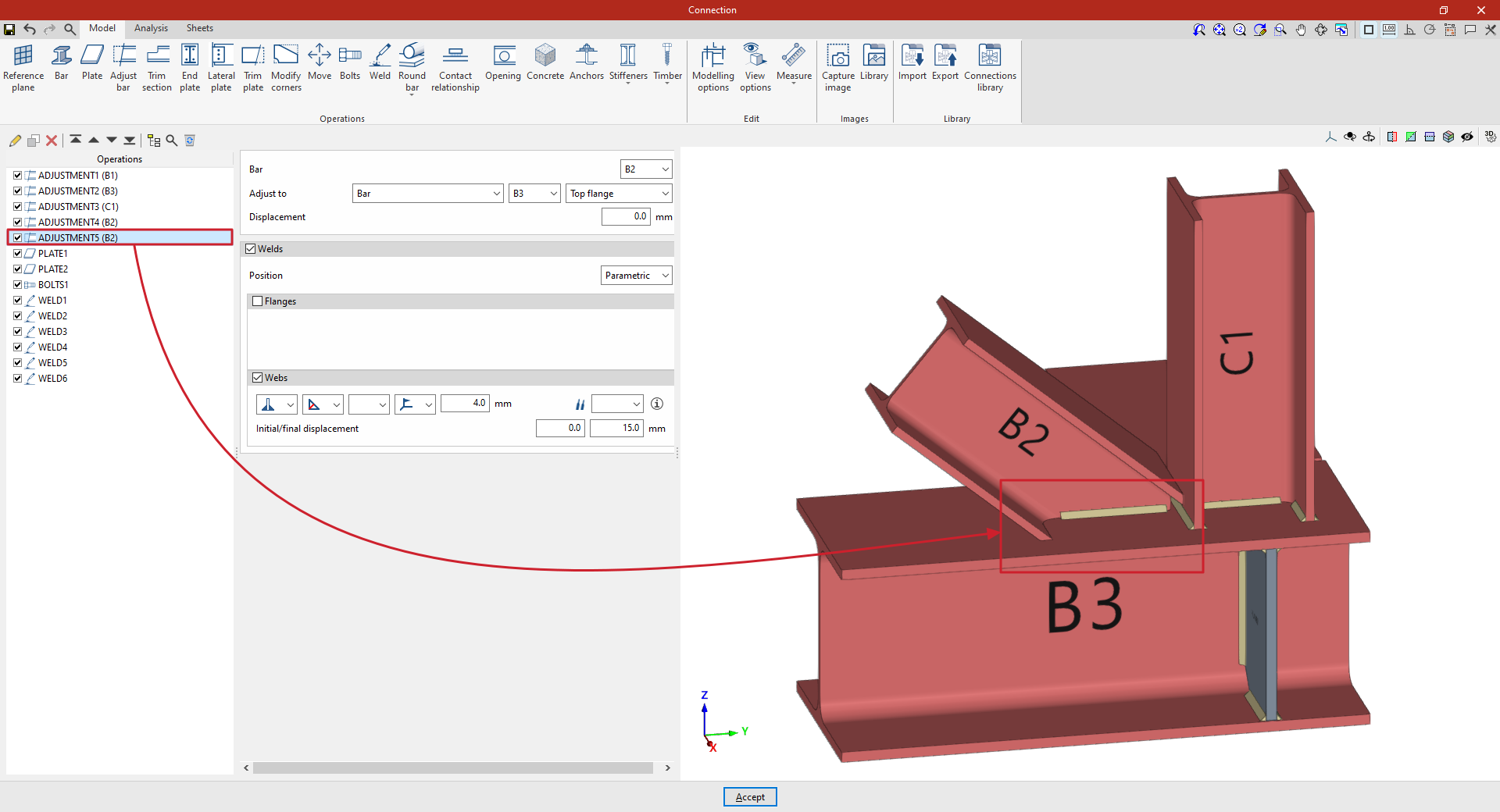
"Adjust bar" function
The "Adjust bar" operation allows you to lengthen or shorten a bar by aligning it with another bar, a reference plane or a plate. It also allows you to generate welds after alignment.

Inserting bar adjustments and selecting elements
Clicking the “Adjust bar” option adds an adjustment operation. While the operation remains selected in the left-hand table, you can configure its parameters using the options in the central panel.
Use the drop-down menus at the top to select the “Beam” to be aligned. You can “Align to” a “Beam”, the envelope of a beam (“Beam (Envelope)”), a “Plate”, a “Reference plane” or a “Plane perpendicular to the beam”.
In the “Displacement” field, you can enter a value to adjust the position of the setting.
Using the adjustment tools, the section is lengthened or shortened to the specified point. The result of the operation is displayed in the viewport on the right.

Defining welds in bar adjustments
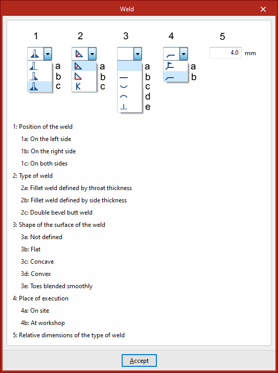
The program allows you to enter the “Welds” for the “Flanges” and “Webs” directly by ticking the relevant boxes. Within each section:
- The first drop-down menu shows various options for defining the position of the weld bead:
- On the left-hand side,
- On the right-hand side,
- Or on both sides.
- In the second drop-down menu, select the type of weld from the available options, which are as follows:
- At an angle, defined by the throat depth,
- At an angle, defined by the thickness of the weld side,
- Or flush-mounted with a double bevel.
- The third drop-down menu allows you to define the shape of the weld surface, which can be undefined, flat, concave, convex or with smooth transition curves.
- The fourth drop-down menu specifies the location where the work will be carried out, whether on-site or in the workshop.
On the right, you can select the “Electrode” from those available. The information button on the right allows you to view its parameters, such as its reference number or the resistance of the filler metal.
You must specify whether the welds have “Initial/final displacement” values. By default, the program places the weld on the flat part of the web, interrupting the weld bead at the radius specified by the section.
Example
In the example shown here, bar adjustment operations are entered to resolve a connection between four bars (C1, B1, B2 and B3):
From this point onwards, the remaining operations required to complete the connection model must be added before the “Analysis” can be carried out.
"Trim section" function
The "Trim section" option is used to trim the selected section based on the dimensions entered. The type of trim can also be defined: straight, with a radius or with a drill hole.

Inserting and defining section trims
To insert the trimming, click on the "Trim section" option in the top toolbar.
Then, in the first drop-down menu, select the "Section" to be trimmed from those available.
Next, indicate the "Position" of the trimming, which can be at the "Top" or "Bottom" of the section.
Under "Type of trim", specify whether it is "Straight", "With chord radius", or "With drill hole":
- In all three cases, the “X” and “Y” dimensions of the cut-out must be specified in the units shown.
- When using cut-outs "With chord radius" or "With hole", the "Chord radius" or the "Hole diameter" is also specified, respectively.
- The image below is provided as an aid to understand the reference system for these dimensions. All of them refer to the envelope of the section, that is, its original geometry prior to the application of adjustments.
- The "Display options" can be used to make the position of the envelope visible in the connection view. To do this, the "Sections" are shown as transparent by clicking in the cell of the "Drawing" column, and the display of the "Envelope" is activated on the right. After clicking "Accept", the envelopes of the sections are displayed in grey.
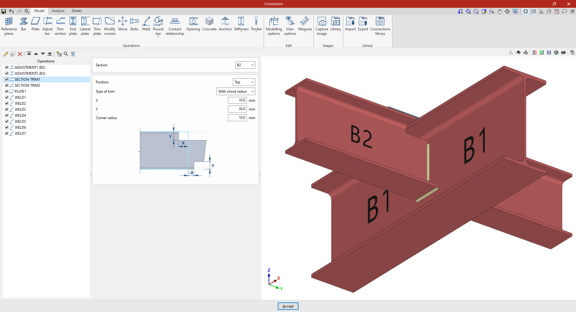
Example
In the example shown here, corresponding to a connection between beams, adjustments have already been made to the sections of beams B2 and B3, which are perpendicular to beam B1.
Next, the necessary trims are made to avoid clashes identified by the program between the beam plates:
- In the first trim, one of the secondary beams, B2, is selected. The cut position is "Top", as the cut is to be made at the top of the section. A "Radius match" cut is used, with an X dimension of 10 millimetres, a Y dimension of 30 millimetres and a radius of 10 millimetres.
- To define the second trim, apply this operation to the other beam by selecting the first one and using the “Copy” option available at the top of the table on the left. In this new operation, in the "Section", beam B3 is selected, with the rest of the parameters remaining the same.
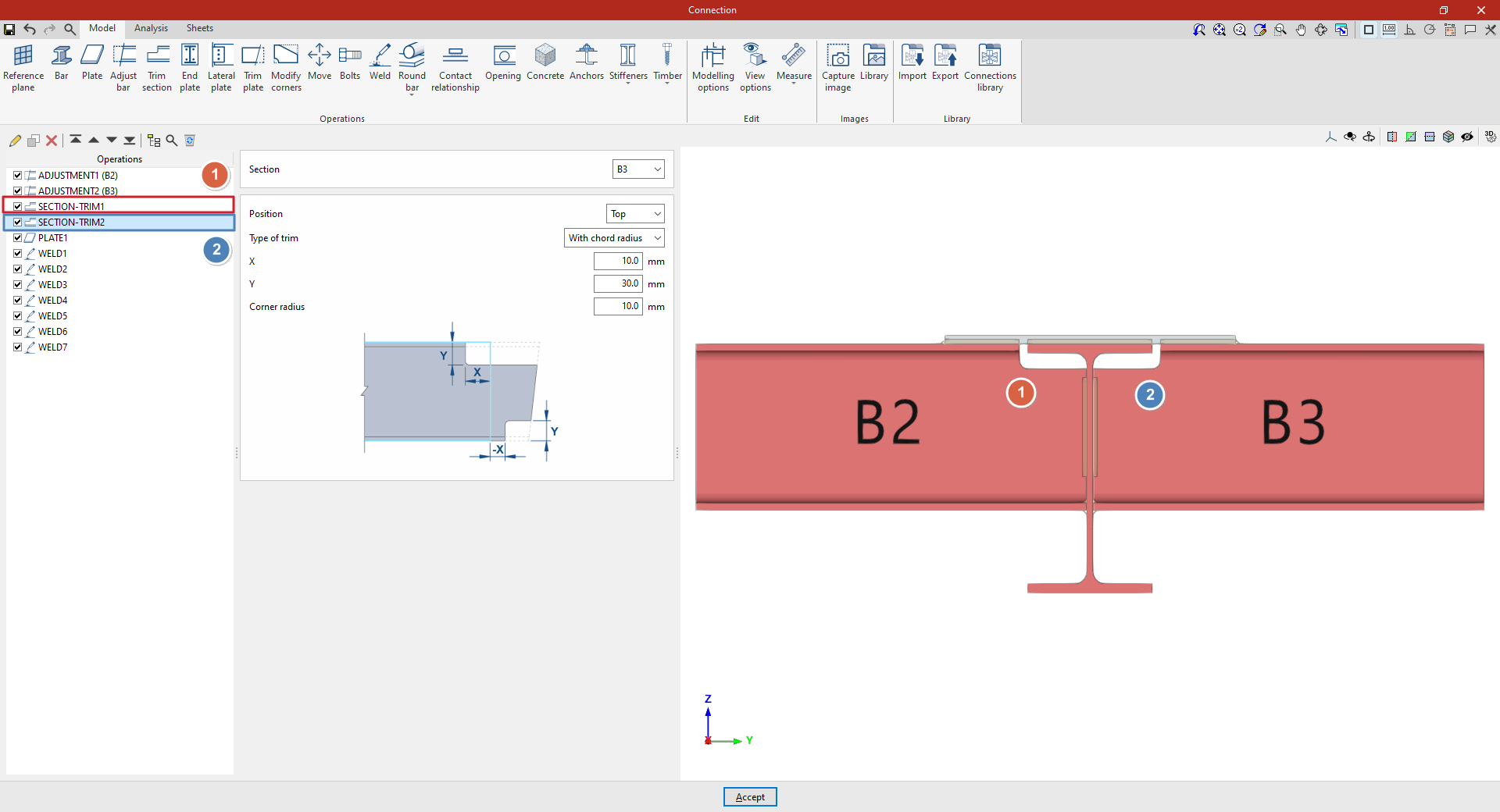
From this point onwards, the rest of the operations necessary to complete the connection model must be added before the "Analysis" of the connection can be carried out.
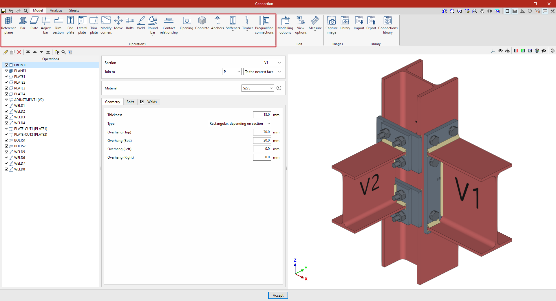
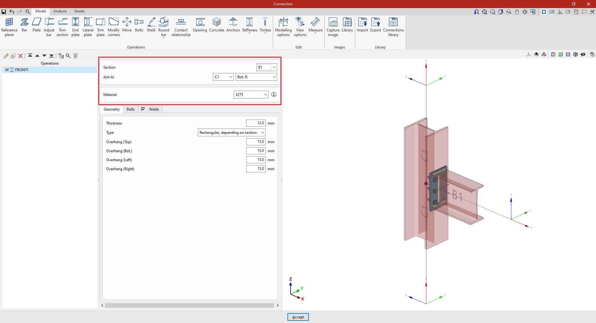
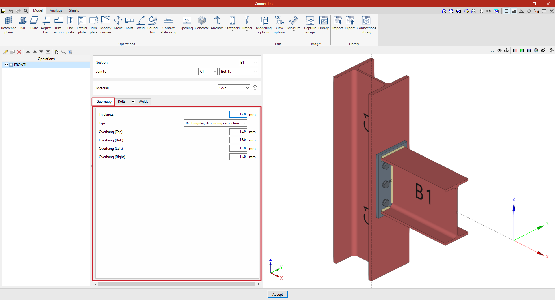
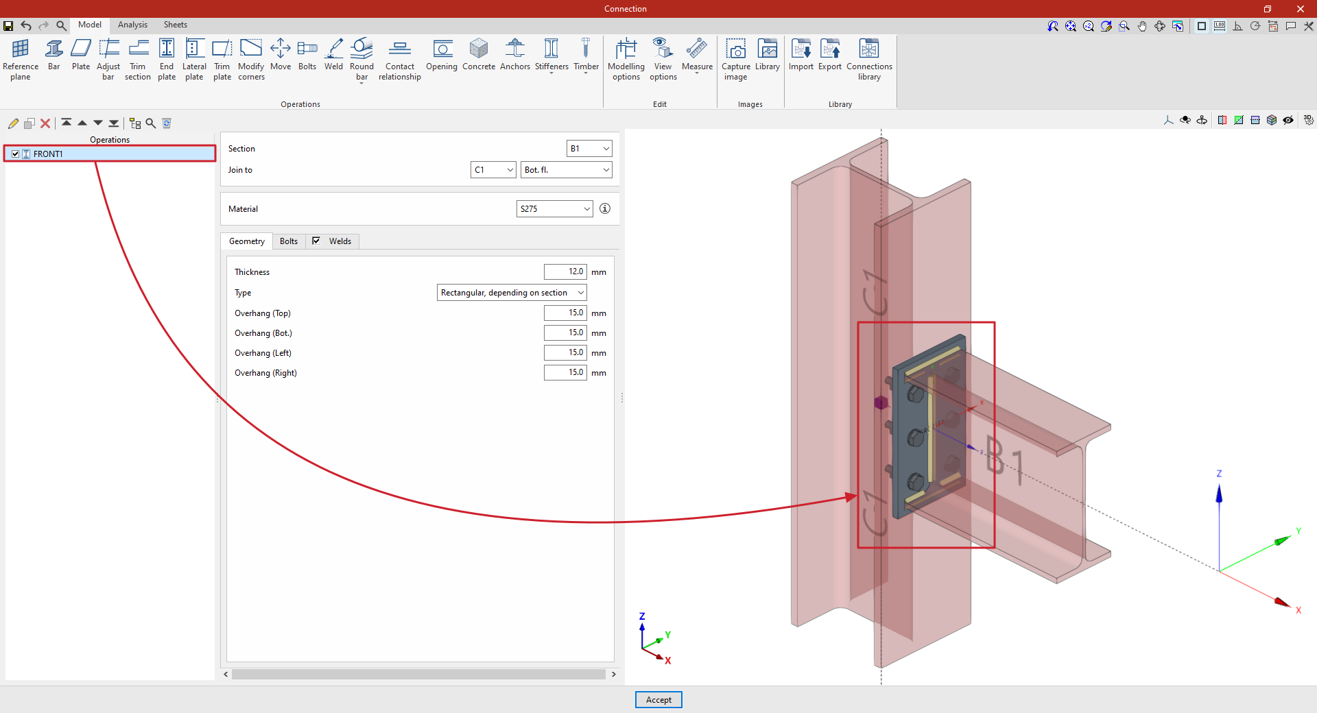
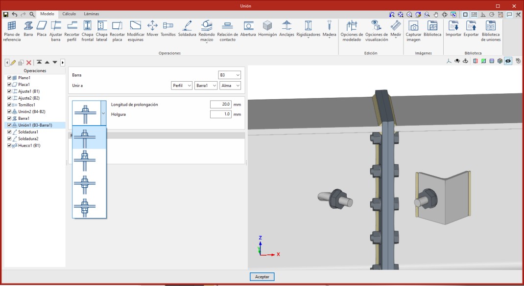
"End plate" function
The "End plate" operation allows one section to be joined to another using an end plate. You can weld the section to the plate and insert bolts between the plate and the section.

Inserting the end plate and selecting the section and material
To insert an end plate, click on the “End plate” option. Once the operation has been selected in the left-hand table, you can configure its parameters using the options in the central panel.
Use the drop-down menus at the top to select the “Section” where the plate is to be placed.
Next, under "Join to", select the bar to which the plate is to be joined. This can be done "To the nearest face", to the top flange ("Top flange"), to the bottom flange ("Bottom flange") or to the "Web" of that bar.
Next, select the “Material” of the plate from those available. The information button on the right allows you to view its specifications.
| Note: |
|---|
| You can use the “Display Options” to identify the upper or lower flange of the sections. To do this, display the “Sections” and “Plates” as transparent by clicking on the cells in the “Drawing” column, and also enable the display of the “Axes”. After clicking “Accept”, you will see that the Z-axis of each beam, shown in blue, points towards its top flange. |
Defining the end plate geometry
In the “Geometry” tab, you define the “Thickness” of the plate.
Next, select the type of plate from the “Type” drop-down menu. This can be:
- “Rectangular, based on section”, defining the top, bottom, left and right overhangs based on the selected section (“Top overhang”, “Bottom overhang”, “Left overhang” and “Right overhang”);
- “Rectangular”, entering the dimensions of the plate directly using “Width X” and “Width Y”;
- or "Circular", in which case the "Diameter" is specified.
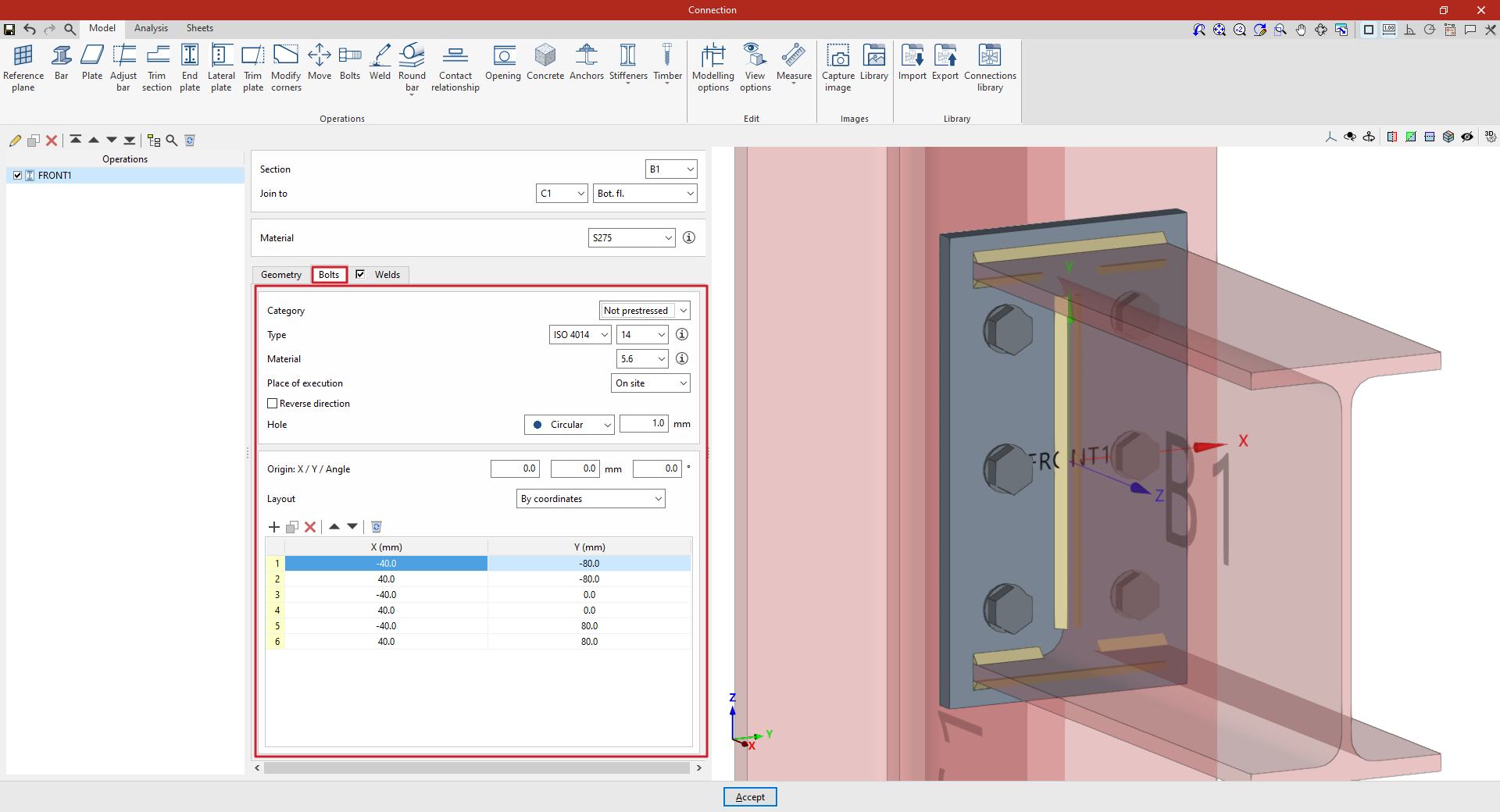
Defining the end plate bolts
The “Bolts” tab is used to specify the bolts that secure the end plate to the bar.
First of all, the following parameters are defined:
- You must specify the "Category" of the bolt as either "Non-preloaded" or "Preloaded".
- Below, you can specify the “Type” of bolt by selecting its series and nominal diameter.
- The “Material” of the bolt is specified below.
- The drop-down menu below allows you to select the "Location", either "On-site" or "In workshop".
- The "Reverse direction" box can be ticked to change the orientation of the bolts.
- Finally, the bolt's "Hole" is specified. This can be:
- "Circular", in which case a "Space" is defined between the hole and the bolt,
- or "Elongated" in either of the two local directions (X or Y) of the sheet metal. In this case, the ratio between the length and the diameter of the hole ("L/d") is defined, with 1 being equivalent to a circle, as well as the "Space" between the hole and the bolt.
Next, in the following section, the bolts are positioned on the plate:
- You must define the local X and Y coordinates and the angle of the positioning origin for the bolts on the sheet metal by entering this data in the "Origin: X / Y / Angle" fields.
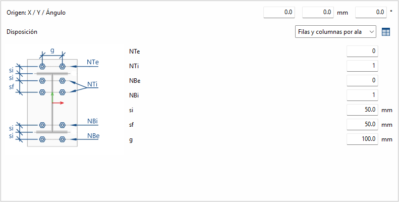
- Below, it is indicated whether the "Layout" of the bolts on the plate is:
- "By coordinates",
- by "Rows and columns",
- by "Rows and columns per flange" (in end plates on rolled I sections),
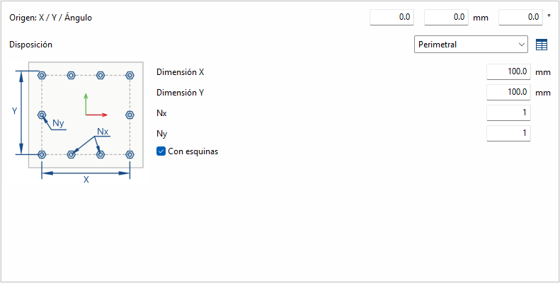
- "Perimeter" on the sheet metal,
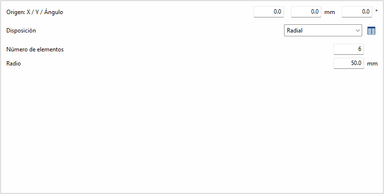
- or "Radial".
| Note: |
|---|
| Further information on these layout options can be found via the following link. The local axes of the plate can be displayed in the viewer via the "Display options" to assist with configuring the bolt layout, with red representing the X-axis and green the Y-axis. |
Defining the welds on the end plate
By selecting the “Welds” tab, you can directly define the welds that join the end plate to the sections on which it is located.
The program allows you to specify a "Perimeter" weld along the contour of the section, or a "Parametric" weld, in which case you must specify the "Welds" for the "Flanges" and the "Webs" by ticking the relevant boxes. Within each section:
- The first drop-down menu shows various options for defining the position of the weld bead:
- On the left-hand side,
- On the right-hand side,
- Or on both sides.
- In the second drop-down menu, select the type of weld from the available options, which are as follows:
- At an angle, defined by the throat depth,
- At an angle, defined by the thickness of the weld side,
- Or flush-mounted with a double bevel.
- The third drop-down menu allows you to define the shape of the weld surface, which can be undefined, flat, concave, convex or with smooth transition curves.
- The fourth drop-down menu specifies the location where the work will be carried out, either on-site or at a workshop.
On the right, you can select the “Electrode” from those available. The information button on the right allows you to view its parameters, such as its reference number or the resistance of the filler metal.
You must specify whether the welds have “Initial/Final displacement” values. By default, the program places the weld on the flat part of the web, interrupting the weld bead at the radius specified by the section.
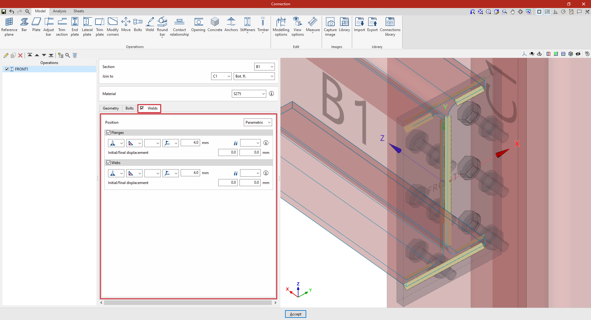
Example
In the example shown here, an end plate is inserted to connect a beam to a column using an end plate:
- The beam is positioned on the "Section" of beam B1, which is to be "Joined to" column C1, specifically to its "Bottom flange". In this case, S275 steel is selected.
- The “Thickness” is 12 millimetres. The type is “Rectangular, depending on section”, and a value of 15 millimetres is entered for all sides.
- Non-prestressed bolts from the ISO 4014 series, with a nominal diameter of 14 mm and made of 5.6 grade steel, are selected. “Circular” type holes with a “Space” of 1 millimetre are specified.
- There are three rows and two columns of bolts, and angled weld beads are defined by the groove depth, which measures 4 millimetres.
At this point, once the model has been completed, you can continue by going to the "Analysis" tab to carry out the analysis of the connection.
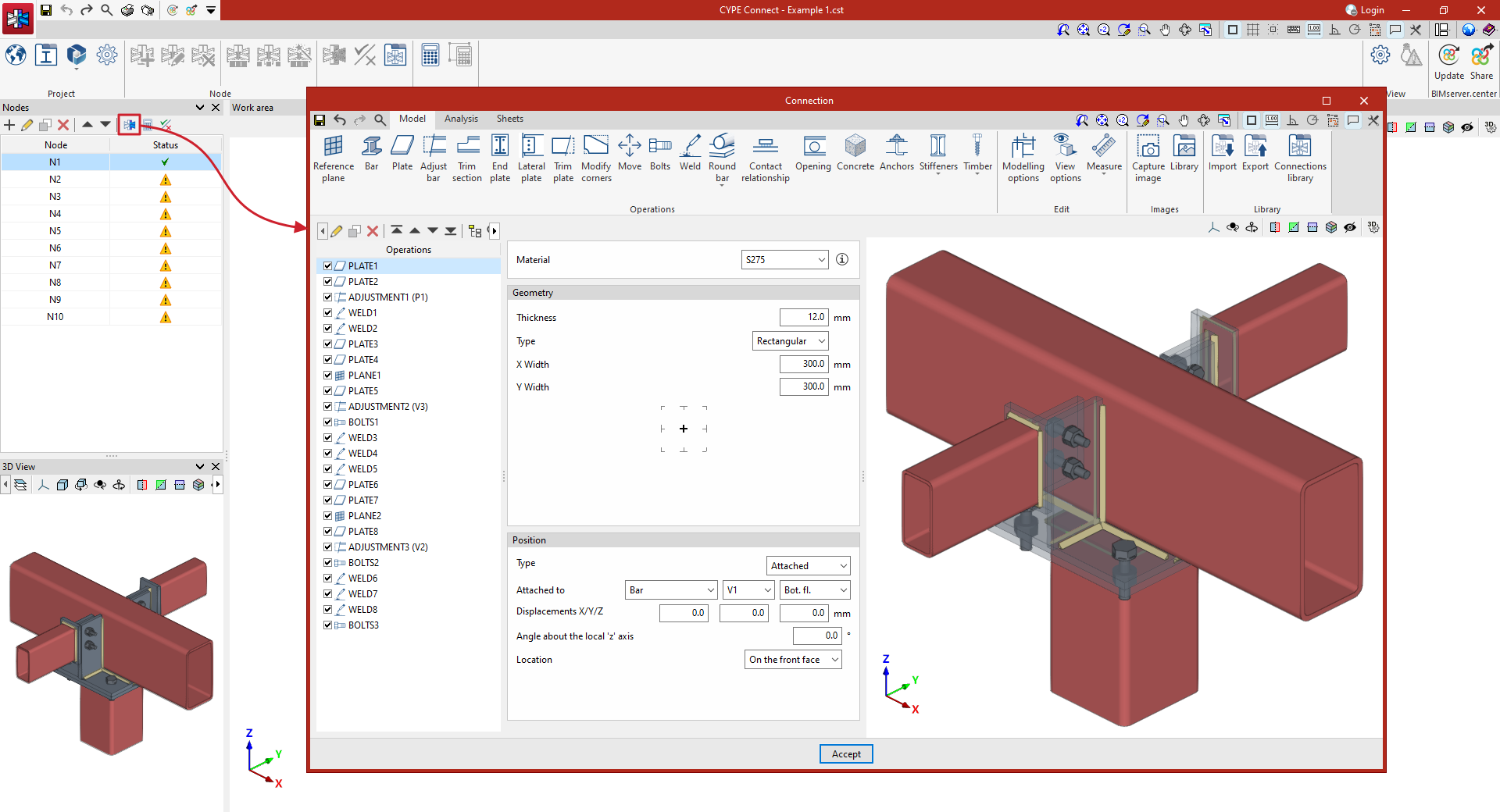
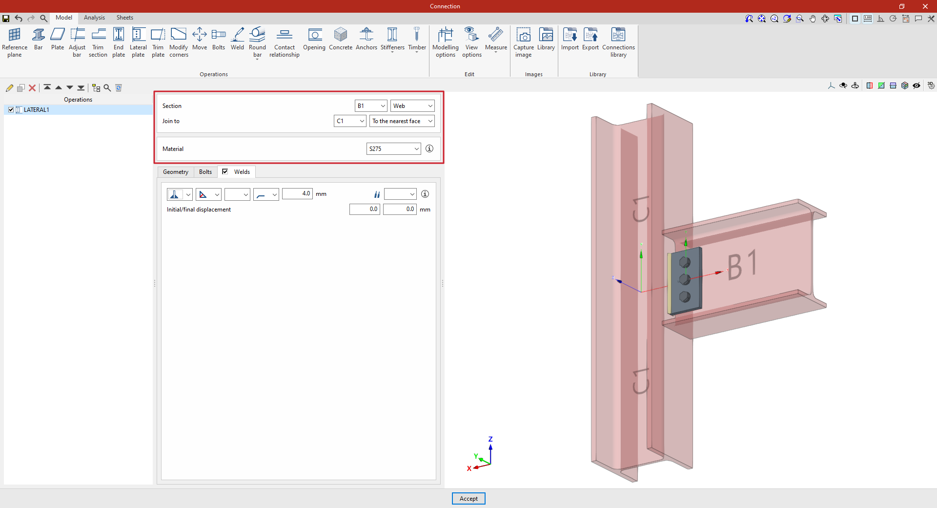
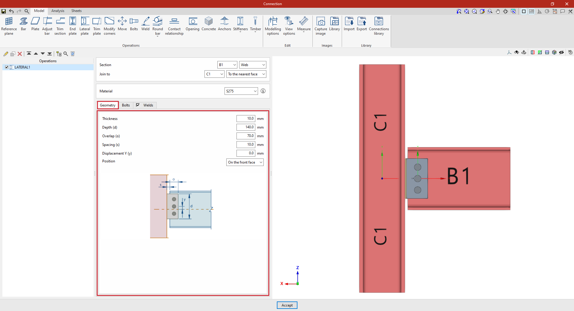
"Lateral plate" operation
The "Lateral plate" method involves joining sections together using a plate that is welded to one of them and bolted to the other.

Inserting lateral plates and selecting sections and material
To insert a lateral plate, click on the "Lateral plate" option. Once the operation has been selected in the left-hand table, you can configure its parameters using the options in the central panel.
Use the drop-down menus at the top to select the “Section” where the plate is to be placed.
Next, under "Join to", select the bar to which the plate is to be joined. This can be done "To the nearest face", to the top flange ("Top Flange"), to the bottom flange ("Bottom Flange") or to the "Web" of that bar.
Next, select the “Material” of the plate from those available. The information button on the right allows you to view its specifications.
Defining the lateral panel geometry
In the “Geometry” tab, the following parameters are defined:
- the “Thickness” and the “Depth (d)” of the lateral plate
- the “Overlap (or)” between the lateral plate and the section where it is fitted
- the “Spacing” between the section on which the sheet metal is placed and the section to which it is attached
- and a “Y-axis offset” of the sheet metal axis relative to the section axis on which it is placed.
You can use the help available via the button at the top right of this section to guide you through setting these values.
You also select the “Position” of the plate, which can be “On the front side”, as in this case, “On the back side” or “On both sides”.
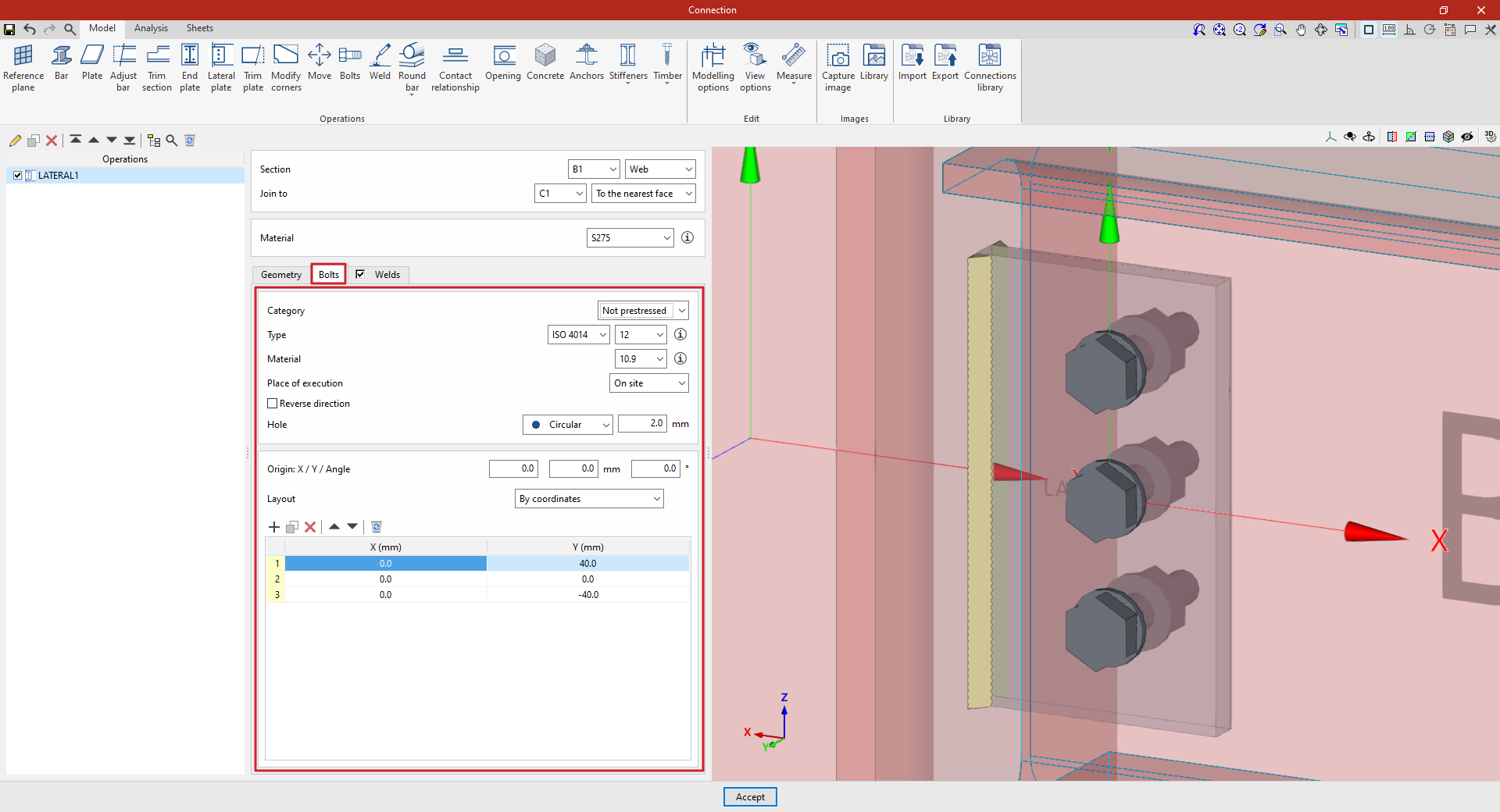
Specifications for the lateral plate bolts
The “Bolts” tab is used to define the bolts that secure the end panel to the section on which it is placed.
First of all, the following parameters are defined:
- You must specify the "Category" of the bolt as either "Non-preloaded" or "Preloaded".
- Below, you can specify the “Type” of bolt by selecting its series and nominal diameter.
- The “Material” of the bolt is specified below.
- The drop-down menu below allows you to select the "Location", either "On site" or "At workshop".
- The "Reverse direction" box can be ticked to change the layout of the bolts.
- Finally, the bolt's "Hole" is specified. This can be:
- "Circular", in which case a "Space" is defined between the drill bit and the bolt,
- or "Elongated" in either of the two local directions (X or Y) of the sheet metal. In this case, the ratio between the length and the diameter of the hole ("L/d") is defined, with 1 being equivalent to a circle, as well as the "Space" between the hole and the bolt.
Next, in the following section, the bolts are positioned on the plate:
- You must define the local X and Y coordinates and the angle of the positioning origin for the bolts on the sheet metal by entering this data in the "Origin: X / Y / Angle" fields.
- Below, it is indicated whether the "Layout" of the bolts on the plate is:
- "By coordinates",
- By "Rows and columns",
- "Perimeter" on the sheet metal,
- Or "Radial".
| Note: |
|---|
| Further information on these layout options can be found via the following link. The local axes of the plate can be displayed in the viewer via the "Display options" to assist with configuring the bolt layout, with red representing the X-axis and green the Y-axis. |
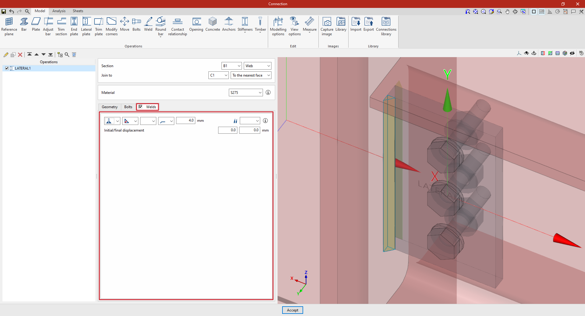
Defining the lateral panel welds
By selecting the “Welds” tab, you can define the welds that join the lateral plate to the bar it is attached to.
- The first drop-down menu shows various options for defining the position of the weld bead:
- On the left-hand side,
- On the right-hand side,
- Or on both sides.
- In the second drop-down menu, select the type of weld from the available options, which are as follows:
- At an angle, defined by the throat depth,
- At an angle, defined by the thickness of the weld side,
- Or flush-mounted with a double bevel.
- The third drop-down menu allows you to define the shape of the weld surface, which can be undefined, flat, concave, convex or with smooth transition curves.
- The fourth drop-down menu specifies the location where the work will be carried out, either on-site or at a workshop.
On the right, you can select the “Electrode” from those available. The information button on the right allows you to view its parameters, such as its reference number or the resistance of the filler metal.
Under “Initial/Final displacement”, you can specify the initial or final displacement values for the ends of the weld bead to adjust its length. If these values are set to zero, the default length is applied across the entire sheet.
Example
In the example shown here, a beam is connected to a column using a lateral plate:
- The plate is positioned on the “Web” of beam B1. It is then specified that it is to be “Join to” column C1, and specifically “To the nearest face”.
- In this case, S275 steel is selected.
- In “Geometry”, a “Thickness” of 10 millimetres, a “Depth (d)” of 140, an “Overlap (o)” of 70, a “Spacing (s)” of 10 and a “Y displacement (y)” of zero are defined.
- Three bolts are added with an “X” coordinate of 0 and “Y” coordinates of 40, 0 and −40 millimetres. Bolts from the ISO 4014 series with a nominal diameter of 12 are selected. The bolt “Material” is 10.9 steel. A “Clearance” of 2 millimetres is specified.
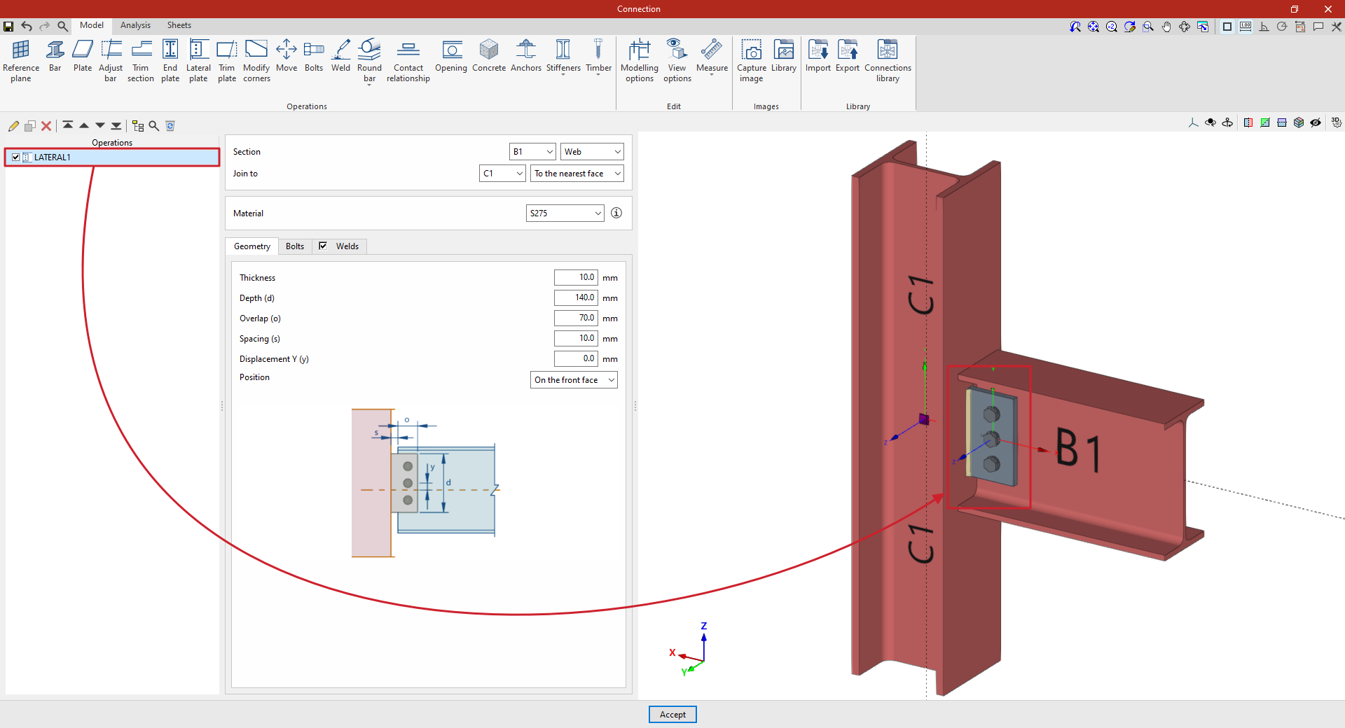
At this point, once the model has been finalised, you can continue by going to the "Analysis" tab to carry out the analysis of the connection.
"Trim plate" function
The "Trim plate" operation allows you to trim a plate using another element. The cut can be made relative to the face of a section, a previously defined reference plane, or another plate.

Inserting a trim in a panel
To trim a plate, click on the “Trim plate” option in the top toolbar.
At the top of the central panel, select the “Plate” you wish to trim from the available options.
You are then prompted to specify whether you want to “Slice with” a “Beam”, another “Plate” or a “Reference plane”, after which you select the beam, plate or plane that defines the trim.
In the case of a beam, in addition to selecting it, you must specify the flange that defines the cross-section, such as the bottom flange (“Bottom flange”), the top flange (“Top flange”) or the “Web” of a double-T section.
The direction of the cut is indicated below; it can be either "On the front" or "On the back".
If desired, you can apply a “Displacement” to the cut-out to adjust its position, as well as add “Welds” by selecting the relevant option.
On the right, in the 3D view of the connection, you can see the effect of the trim made to the plate.
Example
In the example shown here, several plates have been added to connect the section, including top plates for the column and a vertical plate perpendicular to them.
In addition, section adjustments have already been carried out to modify their geometry.
A reference plane has also been defined for use in one of the plate cutting operations.
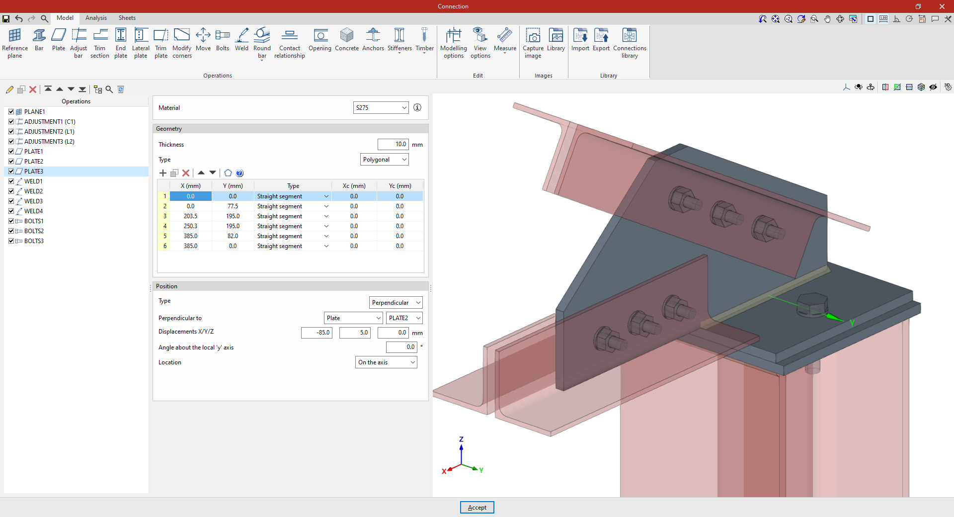
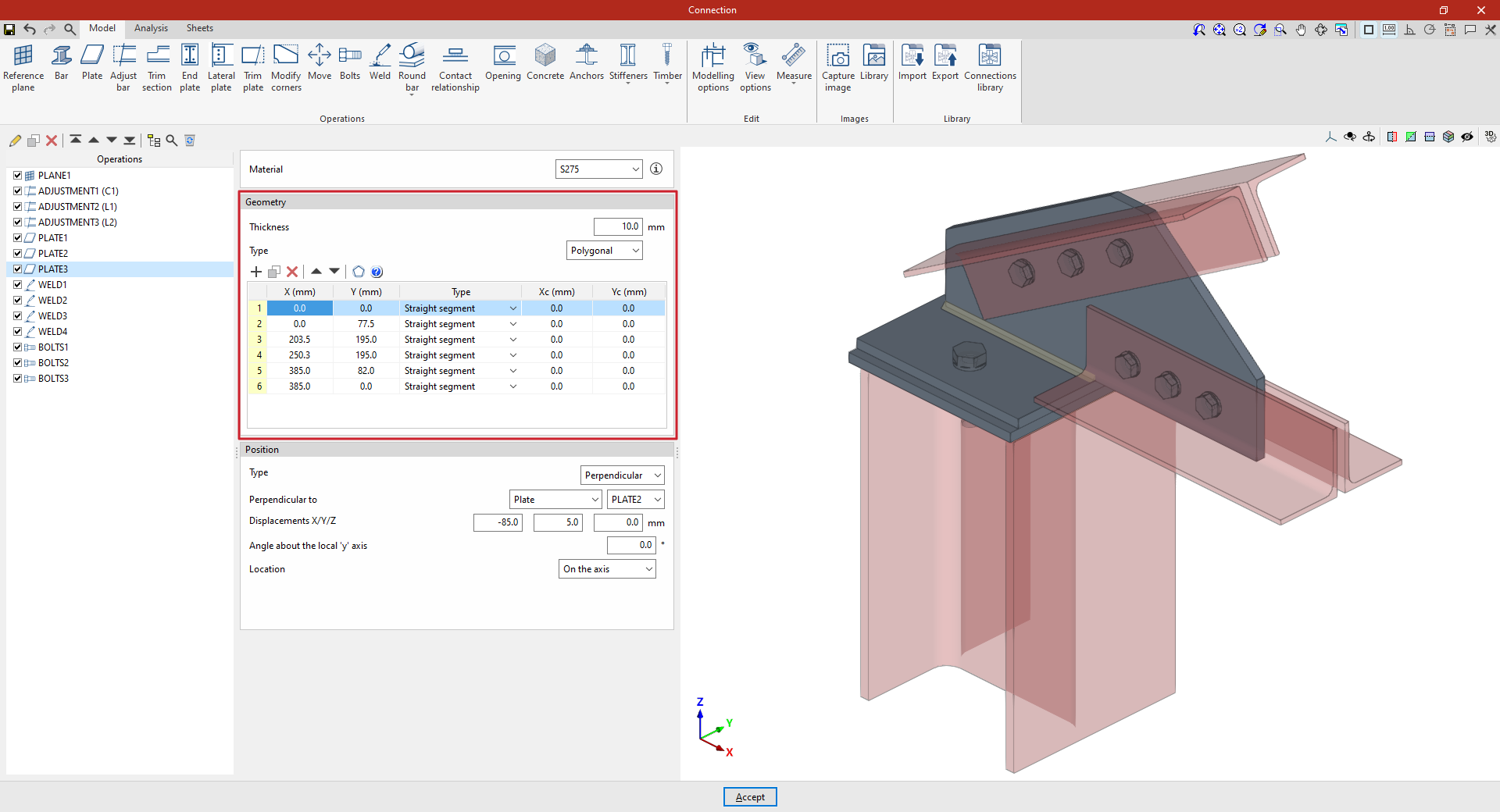
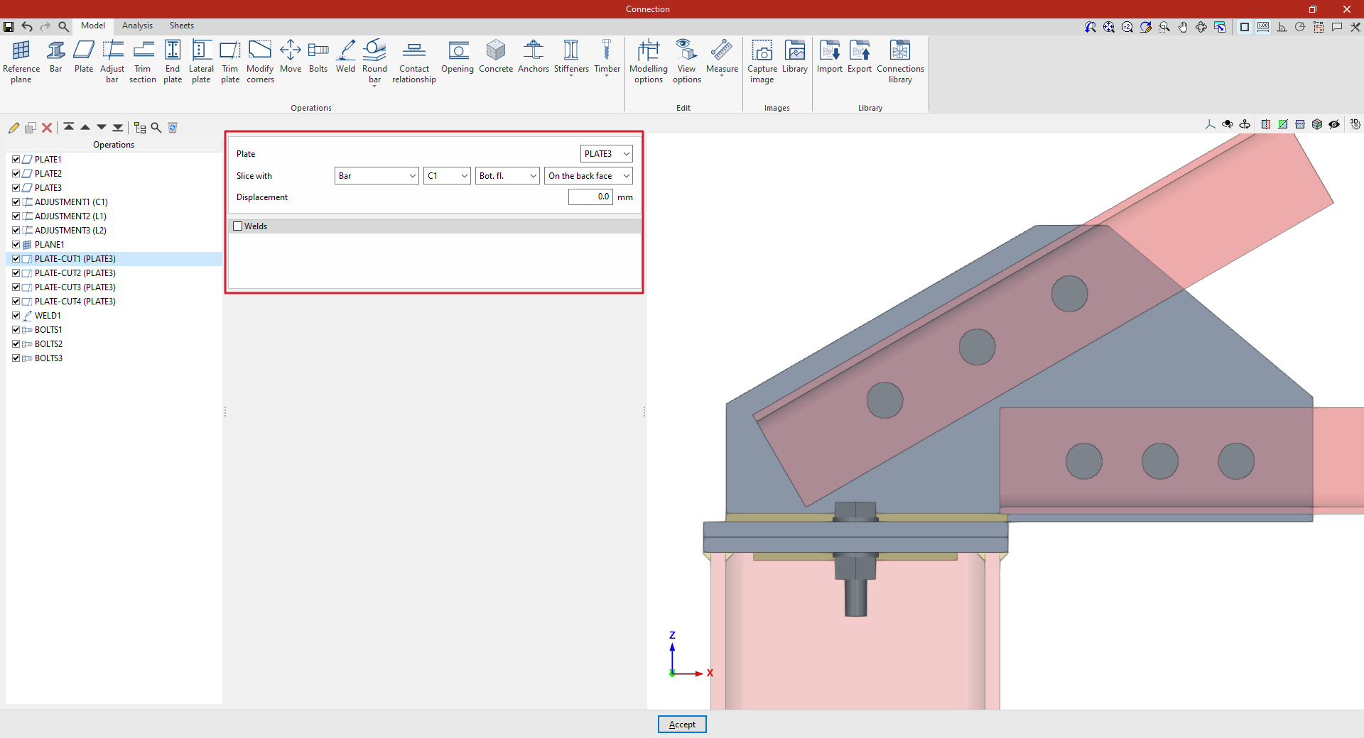
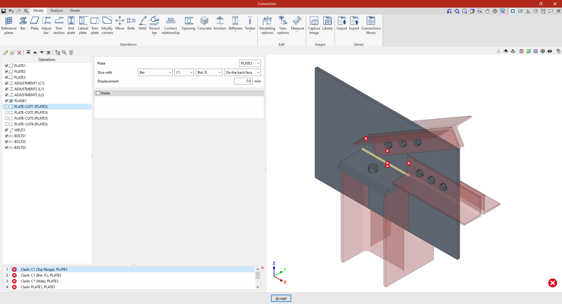
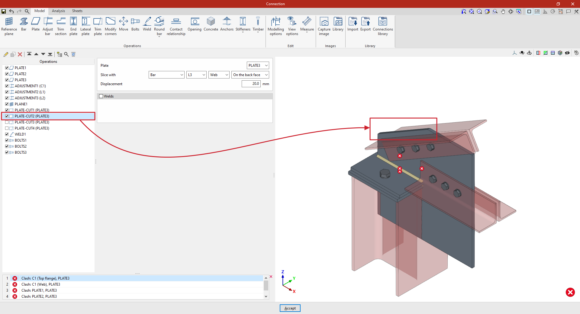
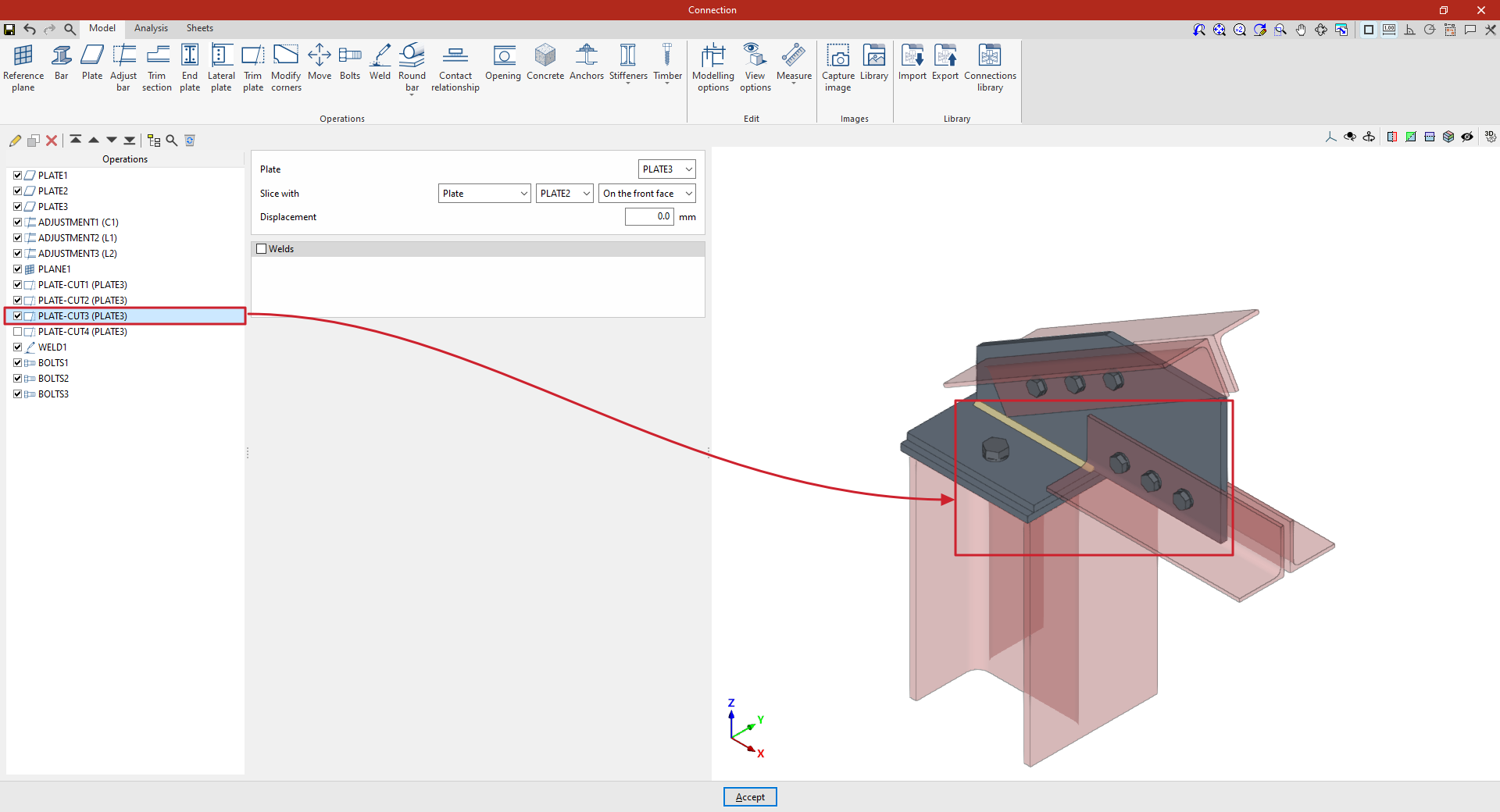
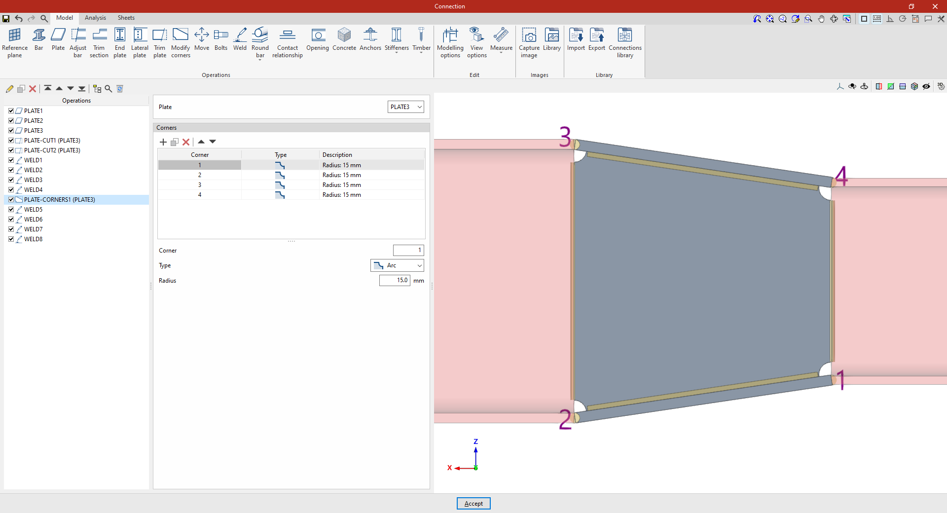
Next, cut-out operations are defined for the vertical plate ('PLATE3') that connects the angle sections to the top cap of the column:
- In the first cut, select “Bar” C1, “Bottom flange”, and “On the back face”.
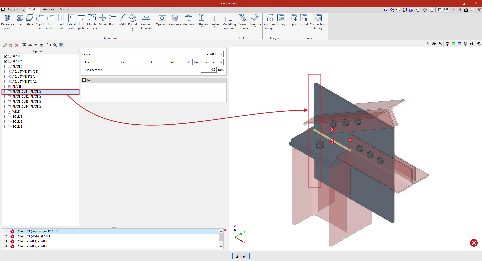
- To create a copy, select the operation in the left-hand table and click the “Copy” button at the top. Next, cut out the same “Plate” using “Section” L3 and, specifically, its “Web”, ensuring that the trim is made “On the back face”. In this case, enter an “Offset” of 20 millimetres.
- The operation is repeated to perform a third trim. In this case, the cut is made using another “Plate”, by selecting its reference from the drop-down menu and then choosing “On the back face”.
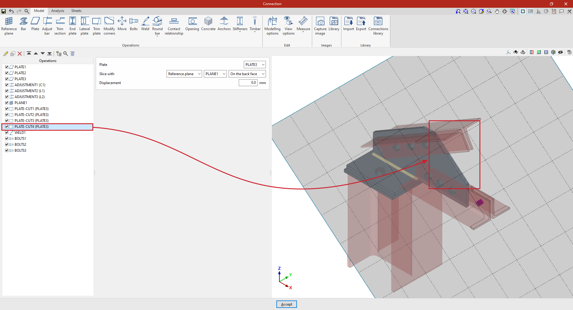
- Finally, a final cut-out is defined on the same “Plate” using a “Reference plane”. Select the plane reference from the drop-down menu and define a trim, once again, “On the back face”.
From this point onwards, the remaining operations required to complete the connection model must be added before the “Analysis” can be carried out.
"Modify corners" function
The "Modify corners" function allows you to edit the shape of the plates by adding cuts to their corners, such as a bevel, chamfer, notch, round or arc.

Overview of the corner modification operation
To perform this operation, click on the “Modify corners” option in the top toolbar.
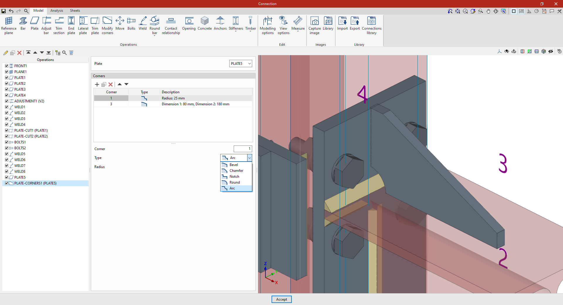
To do this, after adding the operation, select the "Plate" you wish to edit from the drop-down menu. In the viewer on the right-hand side of the screen, the coordinates of each corner of the selected plate are displayed.
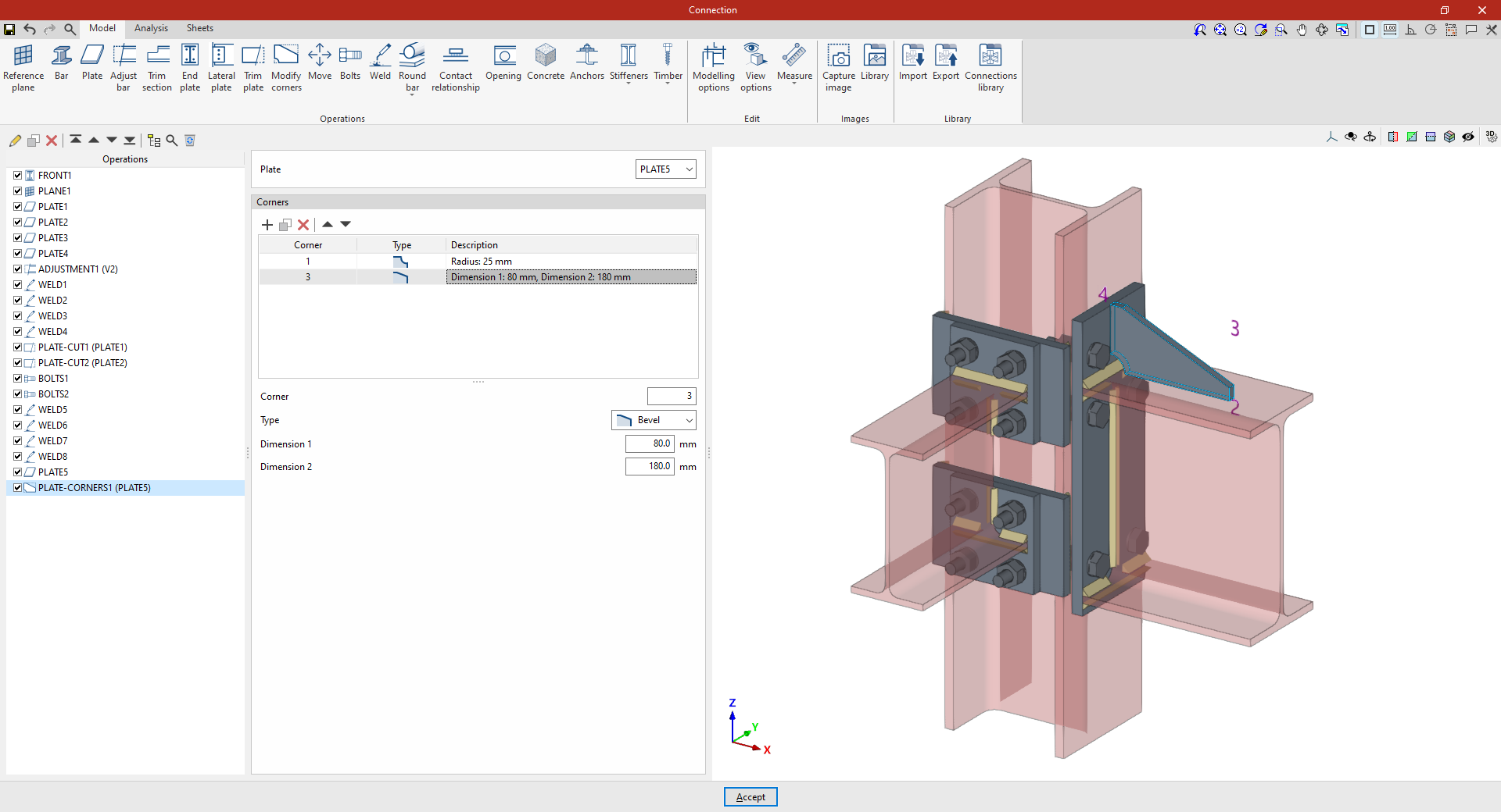
In the "Corners" table, you can define cut-outs at each corner. When you select each row in the table, the "Corner" number is displayed at the bottom; you then define the "Type" of cut and enter its dimensions.
The types of cuts are as follows:
- Bevel
Trims the corner using a bevel. Define the "Dimension 1" and "Dimension 2" of the bevel. - Chamfer
Trims the corner using a symmetrical chamfer. The "Dimension" of the chamfer is defined. - Notch
Inserts a rectangular notch that may have a rounded inner corner. The "Dimension 1", "Dimension 2" and "Radius" of the notch are defined. - Round
Rounds the corner. You can set the "Radius" of the rounding. - Arc:
Trims the corner with an arc, creating a concave shape. The "Radius" of the arc is defined.
Example 1
In the first example, the aim is to modify the geometry of a plate perpendicular to a beam.
A new cut is added to corner ‘1’ in the "Corners" table. In this case, select a "Chamfer" cut and enter a "Dimension" of 25 mm.
Next, a new row is added to the table for “Corner” ‘3’, specifying a "Type" of cut as “Bevel”, with a “Dimension” of 80 mm in one direction and 180 mm in the other.
Thus, when this operation is applied to the selected sheet, it is transformed from a rectangular shape into the desired shape after the cuts are made at the corners.
Example 2
In the second example, a stiffener has been defined that is bolted to the secondary beam, and cuts are to be applied to it.
Add the “Modify corners” operation and, in the “Plate” drop-down menu, select the stiffener.
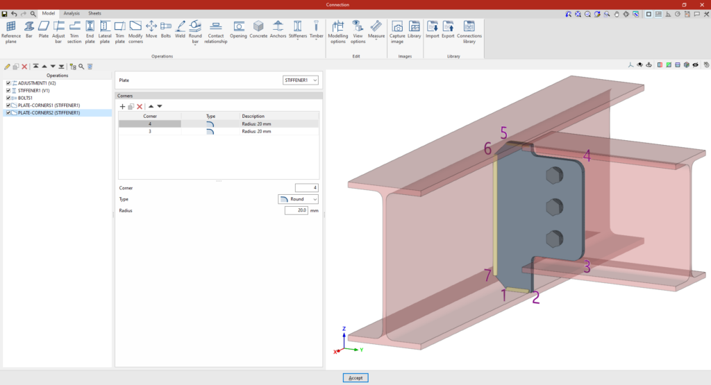
In the “Corners” table, a cut is added to “Corner” ‘6’, of “Type” “Notch”, with dimensions of 20 mm and 105 mm, and a “Radius” of 10 mm.
A new line is added for the ‘5’ corner, with a notch measuring 105 mm by 70 mm and a radius of 10 mm.
As a result, the stiffener is now shown as a cut-out.
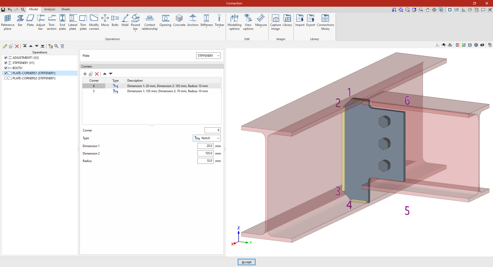
If a “Modify corners” operation is added again, the available corners are those resulting from the previous operations. For example, changes can be applied to corners ‘3’ and ‘4’. To do this, two new rows are added to the table for these “Corners”, selecting “Rounding” as the “Type” in both cases with a “Radius” of 20 mm.
Example 3
In the third example, we want to make cuts at each of the corners of a slab situated between two beams.
Once again, select the “Modify corners” operation and choose “Plate” from the drop-down menu.
Next, add a fillet with a radius of 15 mm at corner ‘1’. Finally, you can create new fillets using the "Copy" option for corners ‘2’, ‘3’ and ‘4’.
"Move" function
The "Move" function allows you to move bars or plates using another element as a reference.

Defining the movement of plates and/or bars
To start the operation, click on the “Move” option in the top bar.
Firstly, the “Direction” of movement of the element is specified in relation to its axes, either “In the Z axis” or “In the XY plane”.
Next, specify the “Element” to be moved, whether it is a “Plate” or a “Bar”, indicating in this case the plate or section of the bar to be considered for the movement.
Next, you must specify the “Edge” you wish to use as a reference point for the movement, whether it is the “Nearest”, the “Furthest” or one specified by the “User”.
Finally, you specify that you wish to “Move to” another “Plate”, another “Bar” or a “Reference plane”, and you can also select “On the front face” or “On the back face” to indicate which face defines the movement.
If necessary, an additional “Displacement” can be applied to the movement.
In this way, the plate moves in its plane until one of its edges reaches the plane defined by the face of the specified element, or the bar is moved by selecting its plates, until its faces are flush with the faces of other elements. For this movement to be possible, both faces must be parallel.
If the reference element changes its dimensions or position, the selected element moves with it automatically.
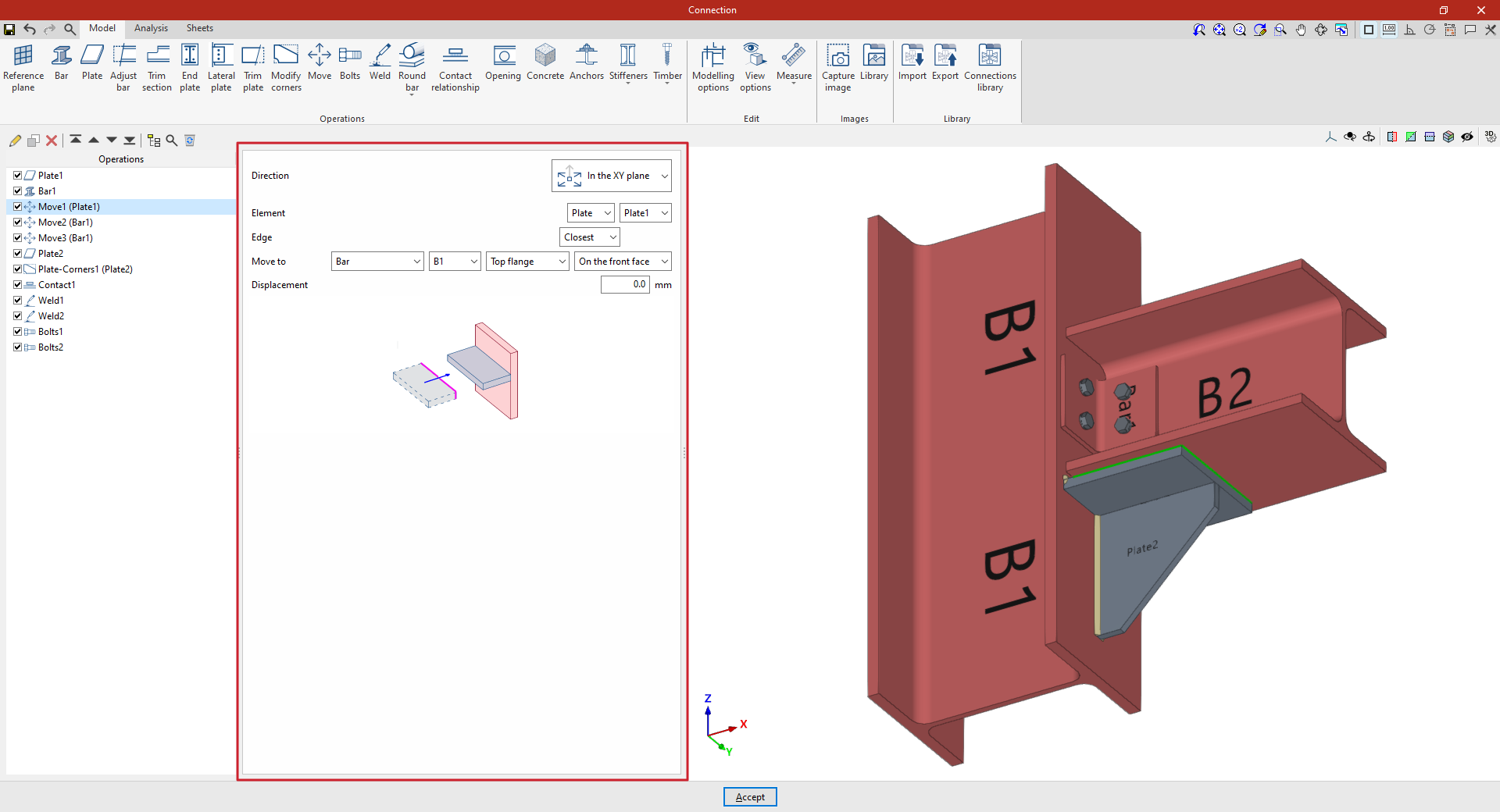
Example
In this example, a plate has been inserted beneath the beam, and an angle section has also been added to form the connection between the beam and the column.
These elements are then moved to adjust their position.
- In the first step, select “In the XY plane” and choose the “Nearest” edge. The plate moves to “Bar” “B1”, specifically to the “Upper flange”, and is positioned “On the front face”.
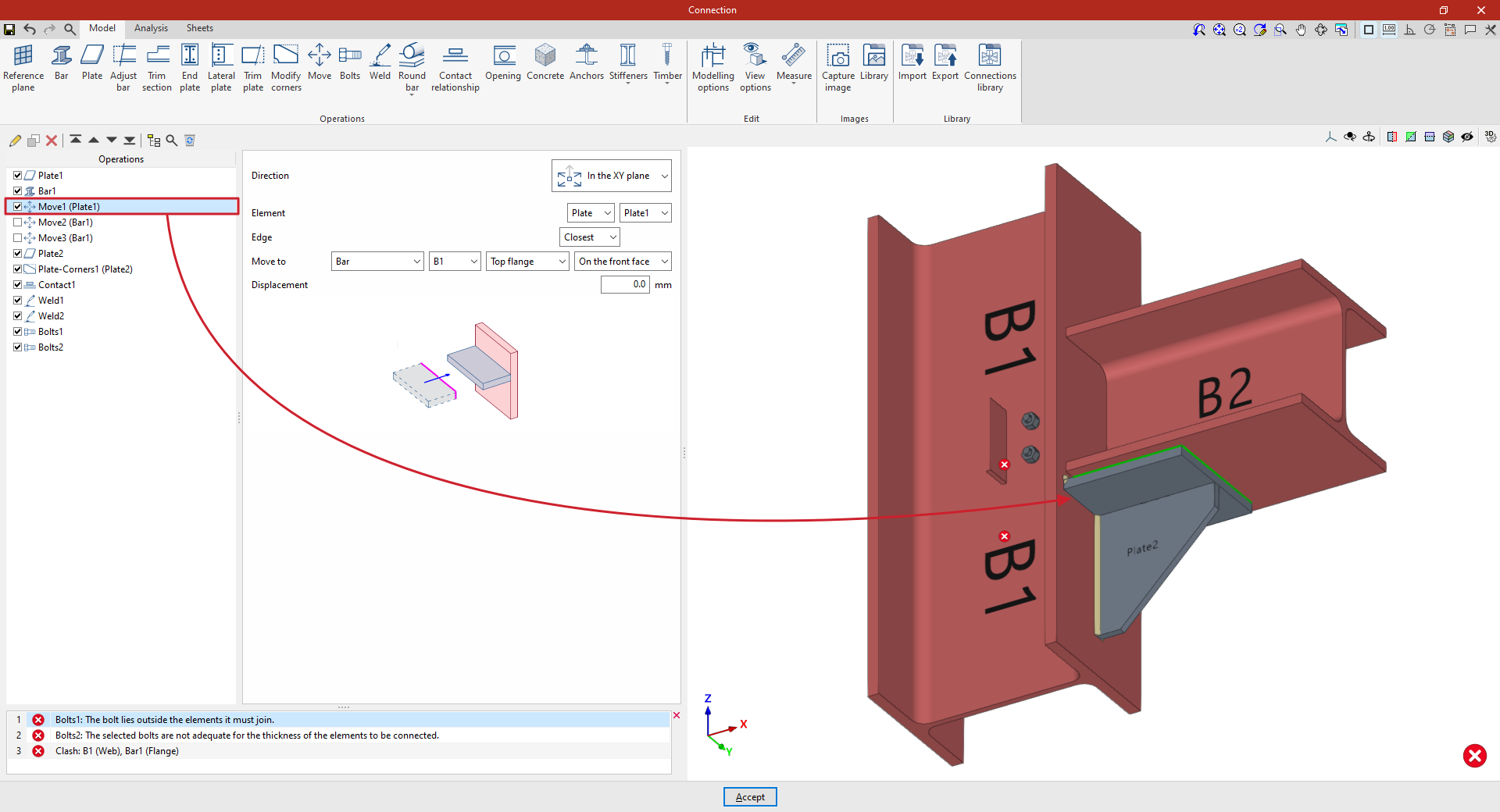
Later on, you can add new “Move” operations to adjust the position of the angle section:
- In the first of these, you specify that you wish to move the beam “Along the Z-axis” and select the “Beam” corresponding to the angle bracket as the “Element”. In the drop-down menu on the right, select the section flange to be considered in the movement; in this case, the “Web”.
Next, specify that you wish to “Move to” the web of beam B2, positioning it “On the back face”.

- By copying the operation, you can define a second adjustment movement. In this case, for the same beam, you specify that you wish to move its “Flange” to the “Top flange” of column B1.
From this point onwards, you should add the remaining operations required to complete the model. Once this is done, you can continue by opening the “Analysis” tab to carry out the connection analysis.
"Bolts" function
The "Bolts" operation is used to insert bolts to join several bars or plates together.

Inserting bolts and selecting elements to be bolted
To add bolts to the connection, click on the “Bolts” option in the top toolbar.
At the top of the central panel, select the “Element” to be bolted from those available; this can be a “Section” or a “Plate”. If a section is selected, you must select the plate or part of the section to be bolted, such as the upper flange (“Top flange”), the bottom flange (“Bottom flange”) or the “Web” of rolled I sections.
Next, in the "Bolt to" drop-down menu, select the second element to be bolted to the first. Again, this can be a “Section” or a “Plate”; if you select a section, you must select the plate or part of the section where you want to place the bolt.
| Note: |
|---|
| If you wish to join more than two elements, simply select the two end elements of the connection. The program automatically detects whether there are any other elements between those selected in the drop-down menus, for example, a plate between two sections. |

Selecting and defining bolts
The following section defines the following parameters:
- You must specify the "Category" of the bolt as either "Not prestressed" or "Prestressed".
- Further down, the “Type” of bolt is defined by selecting its series and nominal diameter. If desired, you can click on the button on the right to open a window where you can view the part number and geometric properties of the “Bolt”, the “Nut” and the “Washer”, as well as the “Available lengths”. At the bottom, it indicates whether the bolt is “Prestressed” or “With lock nut”, as well as the “Number of washers on the side of the head” and the “Number of washers on the side of the nut”.
- The “Material” of the bolt is specified below. By clicking on the button on the right, you can view its specifications, including its “Reference”, “Description”, “Modulus of elasticity”, “Yield strength” and “Fracture limit”, as well as the material of the nut and washer.
- The drop-down menu below allows you to select the "Location", either "On site" or "At workshop".
- The "Reverse direction" box can be ticked to change the orientation of the bolts.
- Finally, the bolt's "drill bit" is specified. This can be:
- "Circular", in which case a "Space" is defined between the drill bit and the bolt,
- or "Elongated" in either of the two local directions (X or Y) of the sheet metal. In this case, the ratio between the length and the diameter of the hole ("L/d") is defined, with 1 being equivalent to a circle, as well as the "Space" between the hole and the bolt.
Bolt layout
Next, in the following section, the bolts are positioned:
- You must define the local X and Y coordinates and the angle of the positioning origin for the bolts on the plate or bar by entering this data in the "Origin: X / Y / Angle" fields.
- Below, it is indicated whether the "Layout" of the bolts on the plate or bar is:
- "By coordinates",
- by "Rows and columns",
- by "Rows and columns per flange" (in front plates on double-T sections),
- "Perimeter" on the sheet metal,
- or "Radial".
| More information: |
|---|
| Further information on these layout options can be found via the following link. |
| Note: |
|---|
| The reference system for the bolt coordinates is the envelope of the selected element, i.e. its original geometry prior to any adjustments being applied. You can use the“Display options” to make the envelopes of the sections visible in the connection view. To do this, display the “Sections” in transparent mode by clicking on the cell in the “Drawing” column and activate the display of the “Envelope” in the right-hand panel. After clicking “Accept”, the section envelopes are displayed in grey. If this function is enabled, the program displays the coordinate origin of the bolts in the viewer, showing the X-axis in red and the Y-axis in green. |
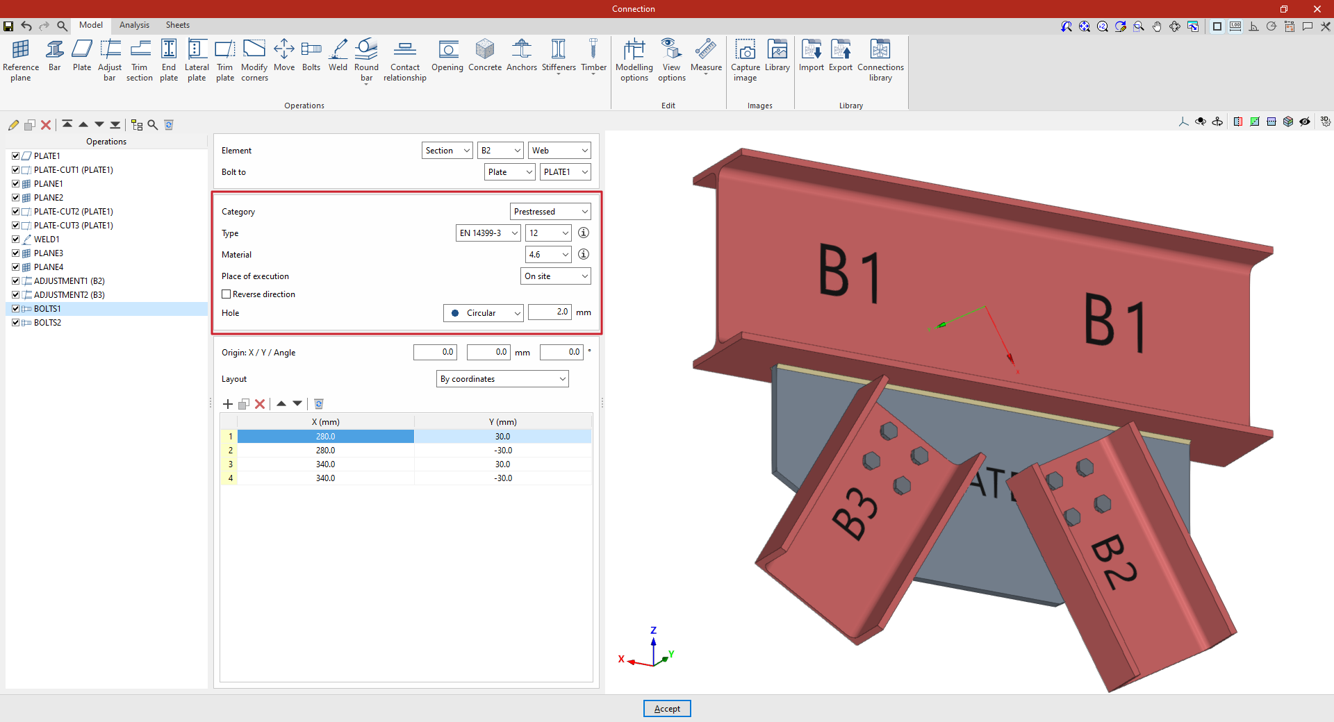
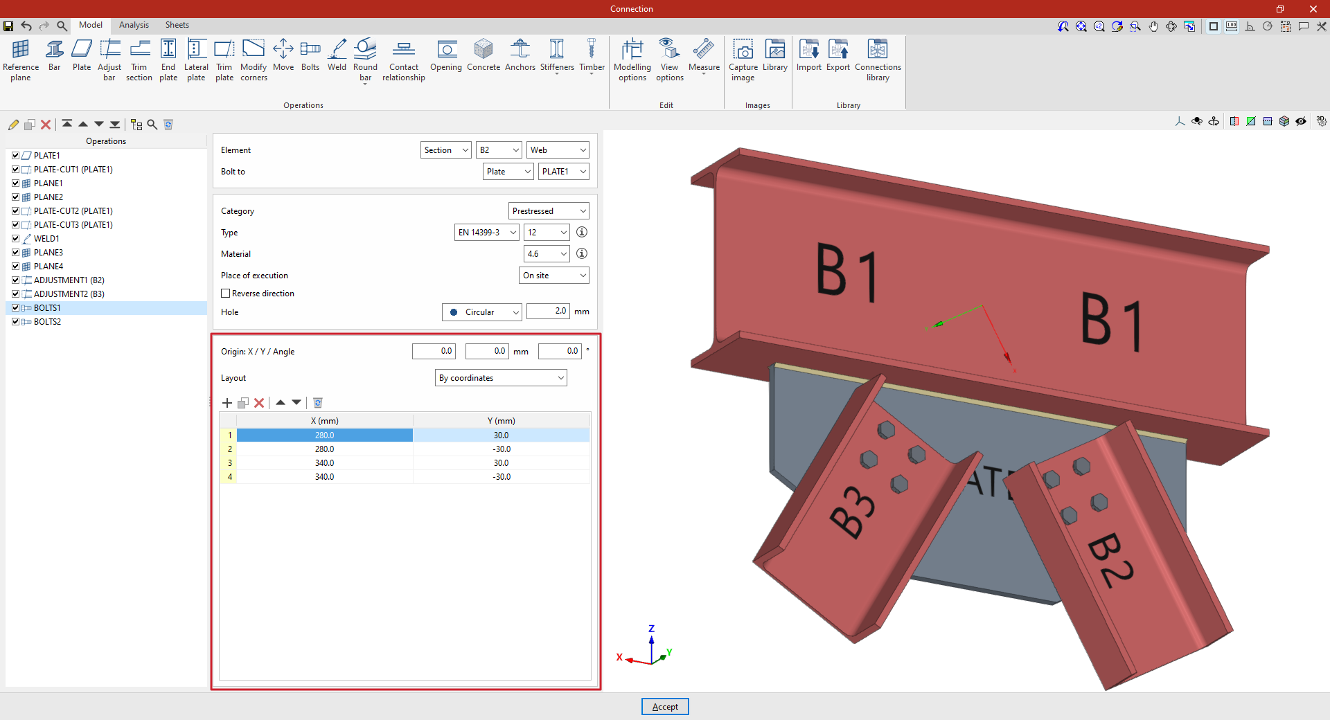
Example
In this example, bolts are used to join a beam to two braces.
A welded plate has been added perpendicular to the lower flange of the beam, and trimming operations have been carried out to modify its geometry. In addition, the sections of the braces have been adjusted to avoid overlapping with the beam.
Next, insert the bolts between each of the diagonal braces and the plate:
- Step 1
First, select “Section” B2, then select “Web”. Specify that you wish to “Bolt to” a “Plate”, selecting the only plate included in the model from the drop-down menu on the right.
Select the EN 14399-3 series and a nominal diameter of 12 from the drop-down menus. Select steel grade 4.6 and set a “Space” of 2 millimetres.
Next, manually define the position of the bolts by clicking “Add” to include them in the table and entering their “X” and “Y” coordinates in the units shown. In this case, four bolts are created manually with X and Y coordinates of 280 and 30; 280 and -30; 340 and 30; and 340 and -30 millimetres.
This adds the bolts connecting diagonal B2 to the welded plate.
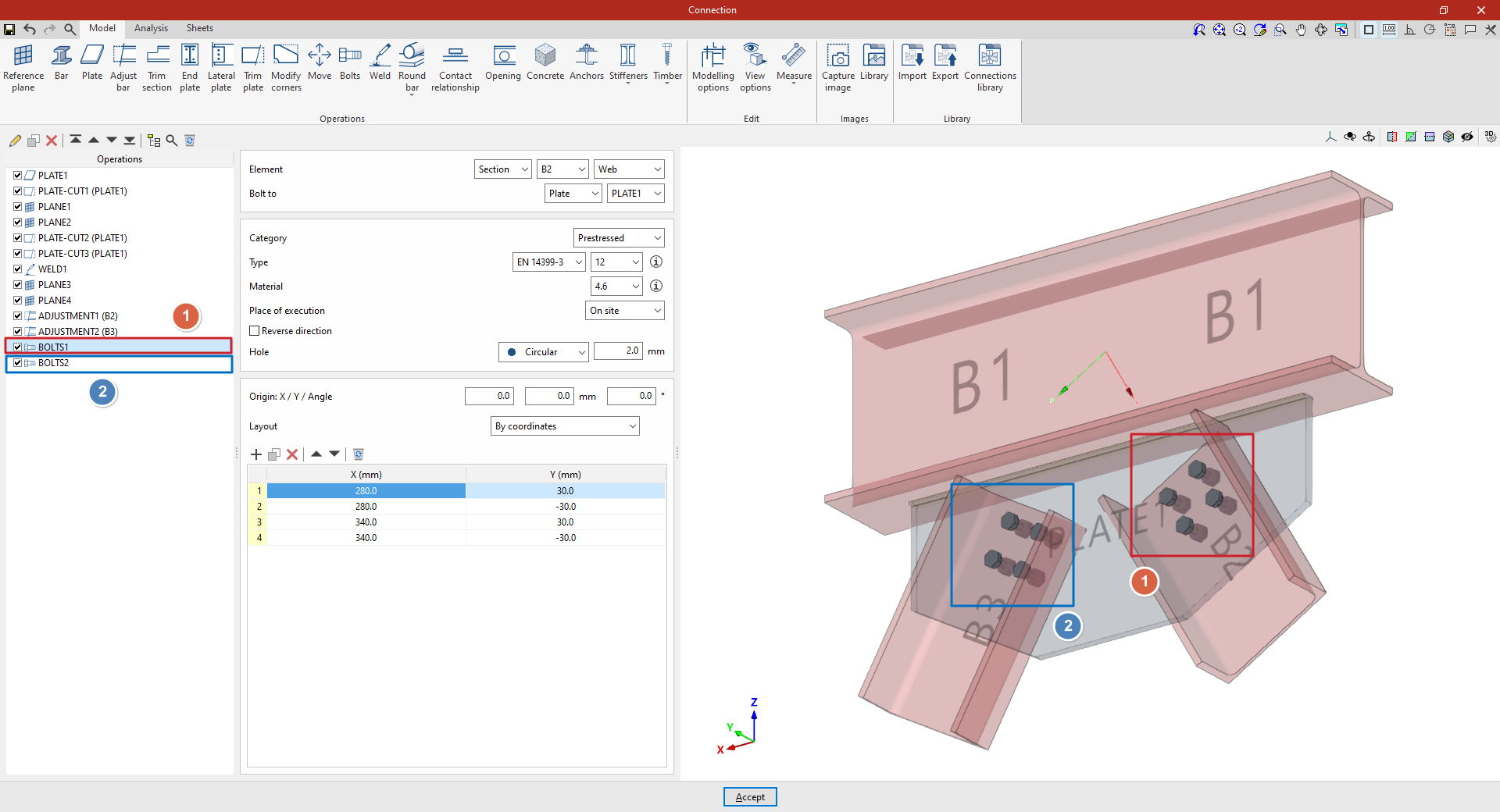
- Step 2:
To add the bolts connecting diagonal B3 to the same plate, select the step from the table on the left and click the "Copy" button at the top. Then, in the new step, change only the "Element" in the drop-down menu at the top to B3, leaving the other parameters unchanged.
At this point, once the model is complete, you can continue by opening the “Analysis” tab to carry out the analysis of the connection.
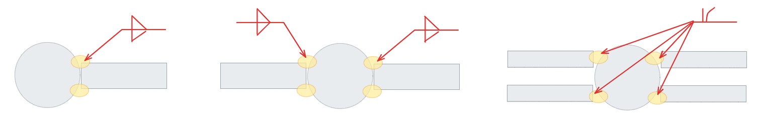
Options for the layout of bolts and anchors
StruBIM Steel and CYPE Connect offer various options for placing bolts and anchors. These options are available when using the "Bolt" or "Anchors" functions, located in the "Operations" group of the "Model" tab in the editing window for each connection. The available options are as follows.
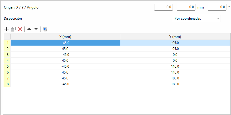
By coordinates
Elements can be placed by directly indicating their X and Y coordinates in a table. This is the ideal option for cases where a more precise location of each element is required.
The origin of the local reference system for openings, bolts and anchors can be edited. Above the coordinate editing table is the "Origin" section with the editing of the "X" and "Y" displacements and the rotation angle. These displacements are applied to the group of elements contained in the table. In bolts, the original reference system corresponds to that of the first plate. In anchors and openings, it corresponds to that of the selected plate.
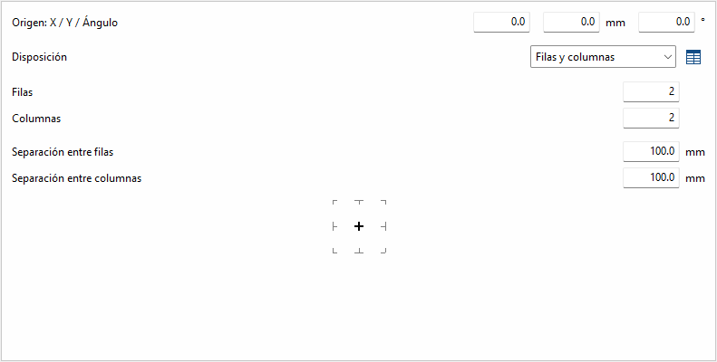
Rows and columns
Distributes the elements regularly in rows and columns, defining the number of elements per row and column and the spacing between them. This is a practical option for homogeneous configurations.
Rows and columns per flange
Typical distribution of end plates in I-sections. In the "End plate" operation, the edge of the bar that is joined to the plate is known, so it doesn't need to be inserted. In other operations, the edge between flange centres is requested.
Perimeter
Given the dimensions "X" and "Y" of a rectangle, it allows the elements to be placed optionally in the corners, and the rest of the elements are distributed along each side according to the number indicated.
Radial
Given a radius and the number of elements, these are placed radially.
| Best practice: |
|---|
| Next to each option, except for "By coordinates", there is a button to convert the layout into a list of coordinates, allowing you to make changes easily if desired. |
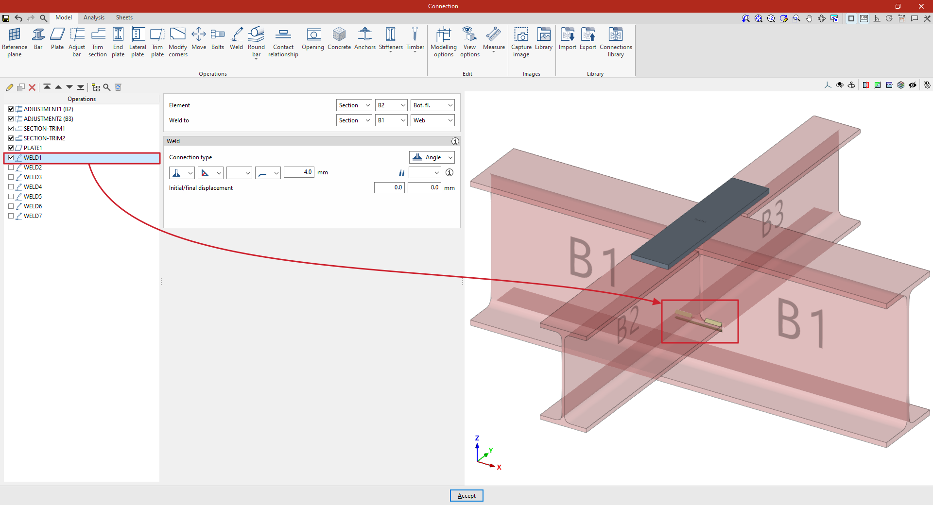
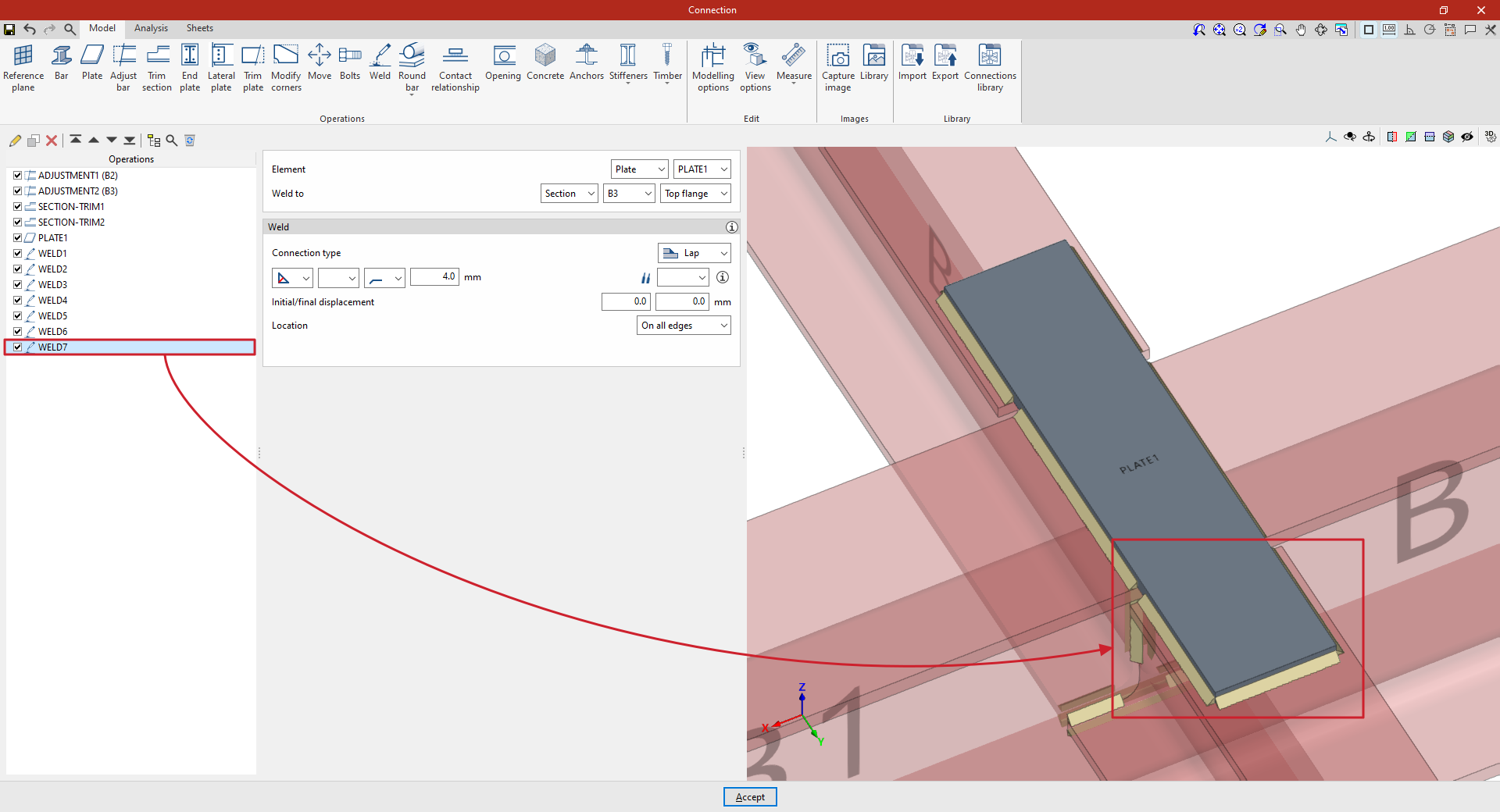
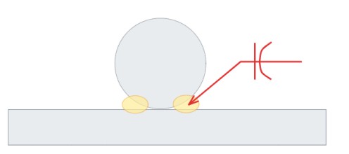
"Welding" function
The "Welding" function is used to insert welds between two components, enabling the creation of fillet, butt and lap welds.

Inserting and defining welds
To insert welds, click on the “Weld” option in the top toolbar.
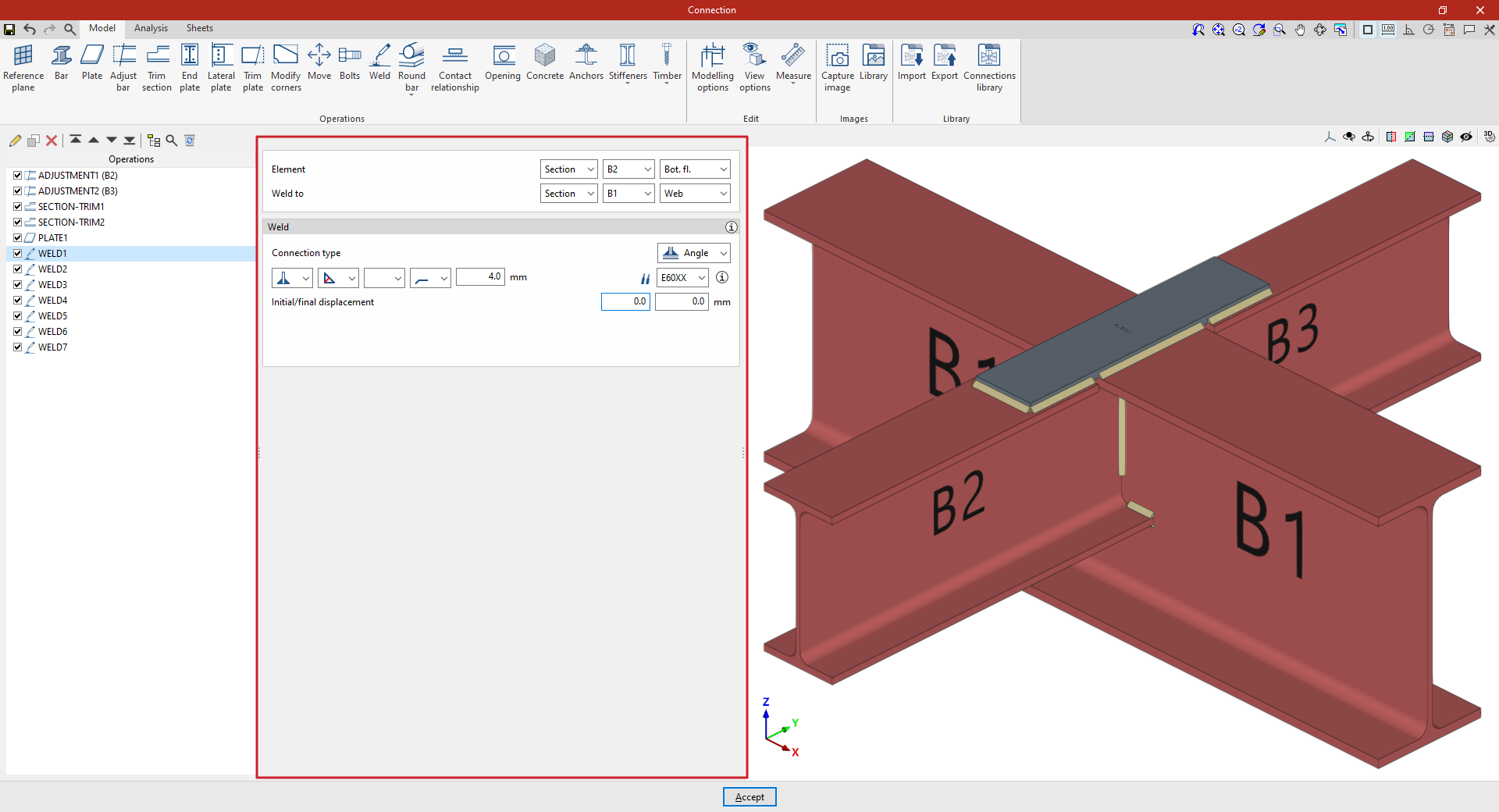
At the top of the central panel, select the “Element” to be welded from those available; this can be a “Section” or a “Plate”. If a section is selected, you must select the plate or part of the section to be welded, such as the upper flange (“Top flange”), the lower flange (“Bottom flange”) or the “Web” of rolled I sections.
Under “Connection type”, select whether the weld is a “Fillet weld” or a “Lap weld”.
The following welding parameters are defined below in the various drop-down menus:
- The first drop-down menu shows various options for defining the position of the weld bead:
- On the left-hand side
- On the right-hand side
- Or on both sides
- In the second drop-down menu, select the type of weld from the available options, which are as follows:
- At an angle, defined by the throat thickness
- At an angle, defined by the side thickness
- Or flush-mounted with a double bevel
- The third drop-down menu allows you to define the shape of the weld surface, which can be undefined, flat, concave, convex or with smooth transition curves.
- The fourth drop-down menu specifies the location where the work will be carried out, either on-site or at a workshop.
The program provides a help section in the top-right corner, where you can find further information about these options.
On the right, you can select the “Electrode” from those available. The information button on the right allows you to view its parameters, such as its reference number or the resistance of the filler metal.
Finally, you specify whether the welds have an “Initial or final displacement”. By default, the program places the weld on the flat section of the wing, with the weld bead interrupted at the radius specified by the section.
In addition, for lap connections, the “Location” option appears, which can be set to “On all edges” or “On a given edge”. In the latter case, the“Edge number” must be specified; this can be found in the connection view.
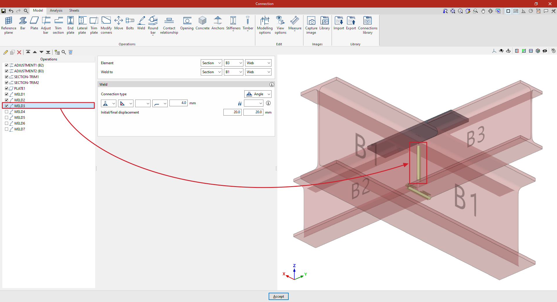
Example
The example shown here demonstrates how to carry out welding operations to join beams.
| Note: |
|---|
| In modelling this connection, adjustments and trimming have been made to the cross-sections of secondary beams B2 and B3, which connect perpendicularly to the main beam B1. In addition, a plate has been attached to the upper flange of beam B1. The necessary welds between the beam cross-sections and between the plate and the beams are then inserted. |
1. First, we describe how to add the welds for the lower flanges of a secondary beam to the web of the main beam. In this case, select “Section” and, from the drop-down menus on the right, select beam B2 and “Bottom flange”. Specify that you wish to “Weld to” another “Section”, corresponding to beam B1, and specifically to its “Web”.
Next, select “Angled” and, in the first drop-down menu, choose the option for both sides. Angled weld beads are defined by the groove depth, set to 4 millimetres.
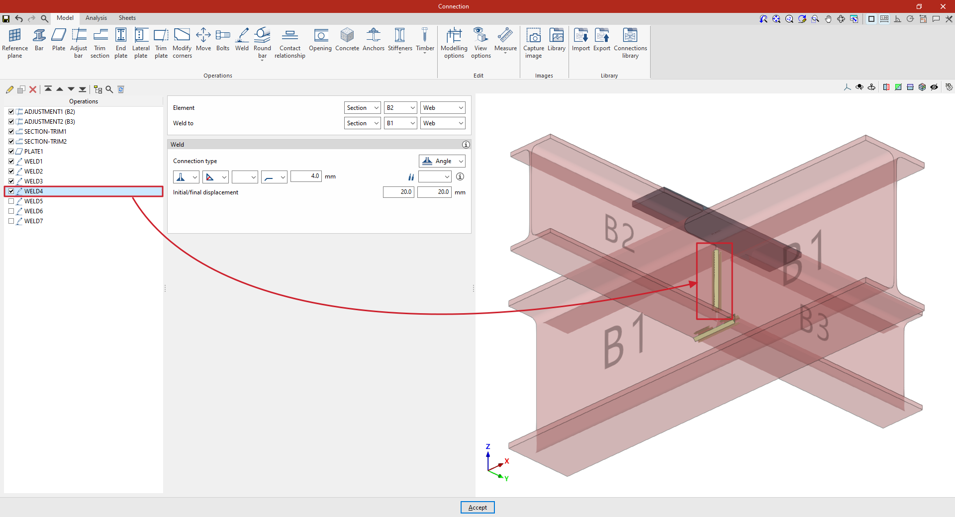
2. To apply this operation to the other beam, after selecting the operation, use the “Copy” option at the top of the table on the left. In the new operation, under the “Element” section, select beam B3, leaving the other parameters unchanged.
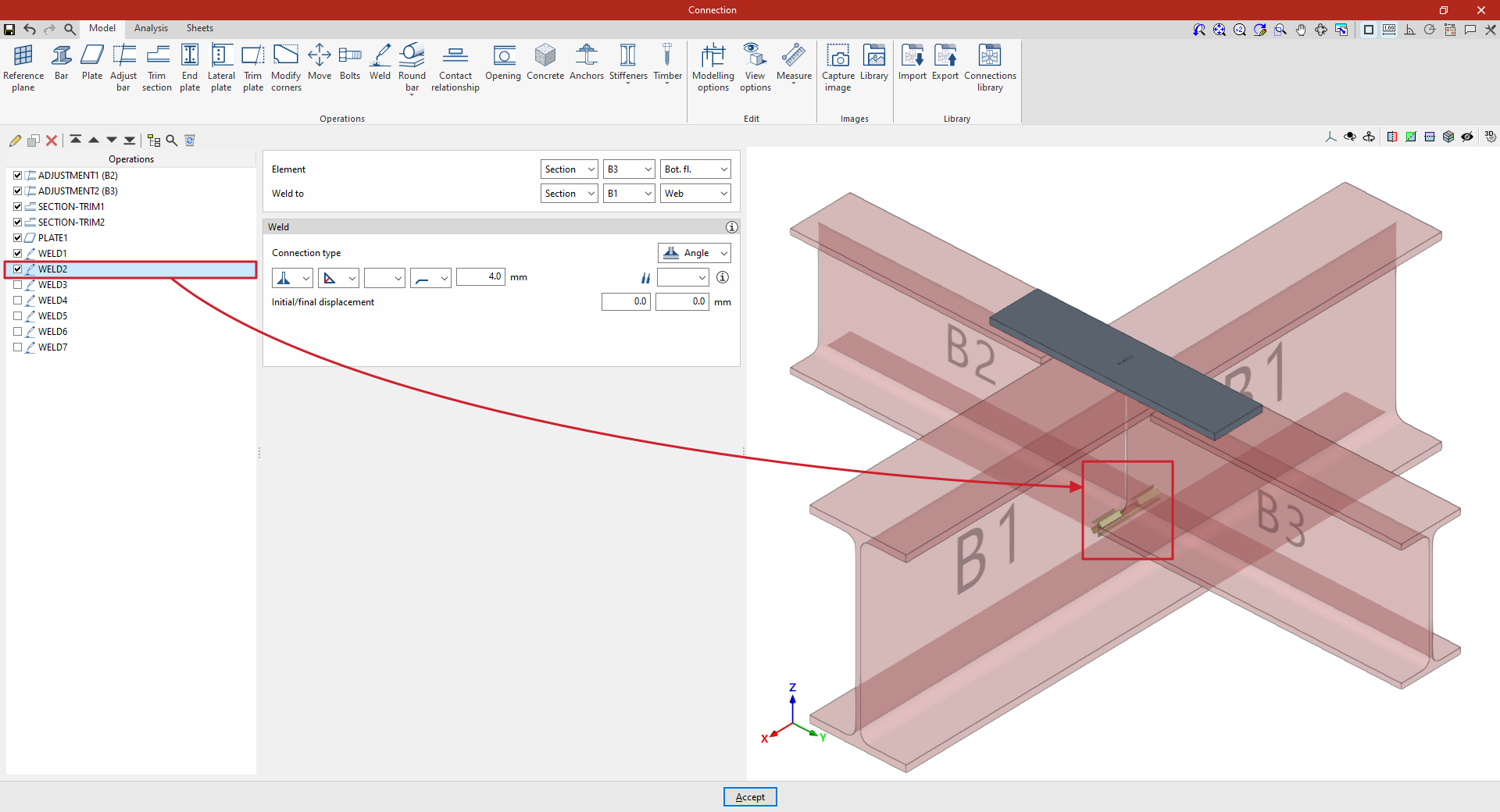
3. A new copy of the previous operation is created to apply it to “Section” B3, and specifically to its “Web”.
This defines the weld on the web of the secondary beam, which by default runs along its entire length. The length of the weld can be adjusted by entering an “Initial and final displacement” of 20 millimetres in both cases.
4. This procedure is repeated to apply it to the “Web” of “Section” B2, thereby completing the welds between the beam sections.
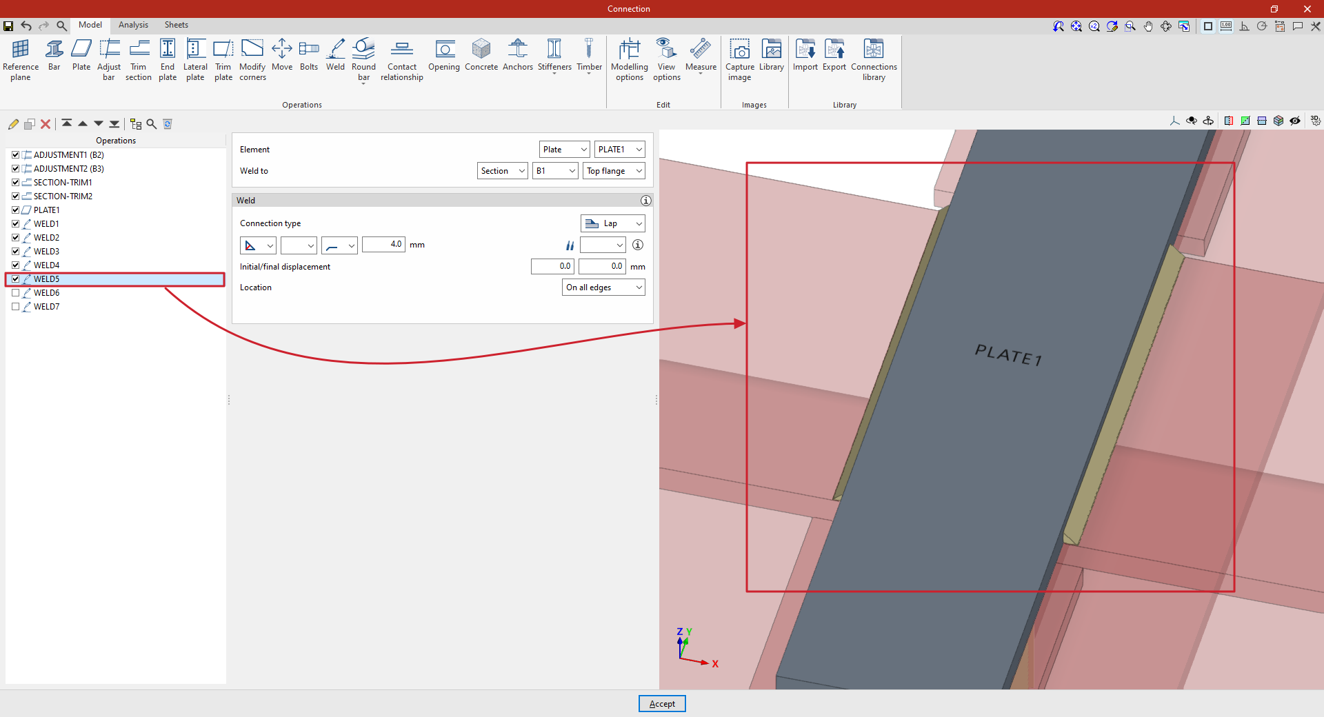
5. Next, define the welds between the plate and the beams. To do this, click on “Weld” again and, under “Element”, select “Plate”, choosing the single plate added to the model from the drop-down menu on the right.
Firstly, it is specified that you wish to “Weld to” “Section” B1, and specifically to the “Top flange”.
Within the “Welding” parameters, the “Connection type” is defined here as “Overlap”. Once again, an angled weld bead is defined by the groove depth, which is set to 4 millimetres.
“Alignment” is set to “All edges”.
6. To weld the plate to the secondary beams, copy the operation and apply the weld to section B2.
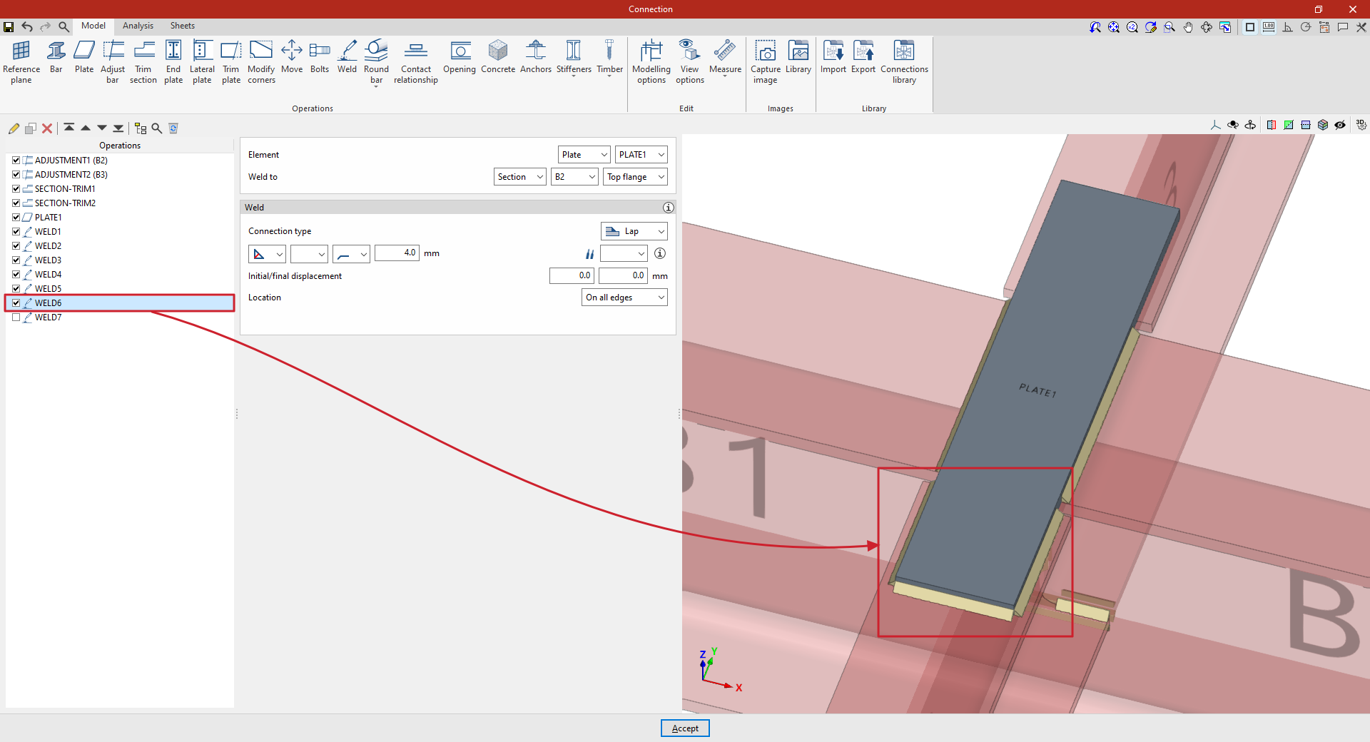
7. Finally, copy the operation again and select section B3, keeping the other parameters unchanged.
At this point, once the model is complete, you can continue by opening the “Analysis” tab to perform the analysis of the connection.
Connection with solid round bars
Connections with solid round bars can be used in CYPE Connect and StruBIM Steel. Unlike other bars, these bars are discretised with a linear element. Although the implementation focuses on solid round bars, if a solid square bar is used, it will be treated in the same way.
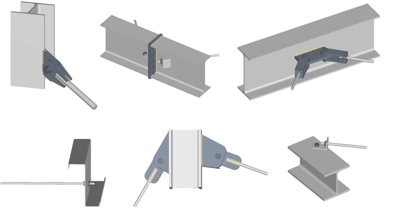
To do this, within the "Operations" group of the "Model" tab in the editing window of each connection, use the "Round bar" group, which displays a menu with the different operations available.
Welding
This operation allows you to weld a solid bar to a plate whose surface is parallel to the bar's directrix.
Welding can be done in two ways:
- Between the bar and the surface of the plate
Welding is allowed on one side or both sides of the bar. The weld will be of the flare-bevel weld type. - Between the bar and the edge of the plate
Different types of welding may be used: flared bevel, angle or edge preparation. The most suitable choice will depend on the thickness of the plate and the diameter of the bar.
Opening at intersection
In this operation, a bar and a plate are selected, and an opening is created in the plate at the point of intersection with the bar. The hole is shaped like an elongated drill hole.
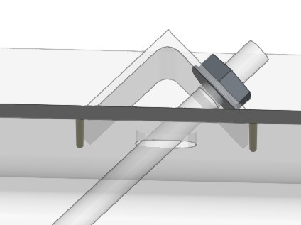
Threaded connection
This operation allows the end of a round bar to be joined to a plate using nuts. To do this, the bar and the plate to which it is joined are selected.
There are several nut layouts, and users must define the length of the tie rod from the last nut, as well as the clearance of the hole. In addition, the reference of the nut and the washer are requested. If the corresponding box is checked, it is possible to manually define the text string; by default, this is generated automatically based on the diameter of the bar. It should be noted that it is not linked to the references in the bolt libraries.
The bar does not have to be perpendicular to the plate. In these cases, users can specify the type of washer or additional device to be placed (see example). This case is not currently represented in the 3D view.
Connecting plate
This operation can place plates using a solid round bar as a reference. In addition to facilitating its positioning, it allows you to generate slots in the plate to fit the bar and apply welds.
| Note: |
|---|
| Bars are linear elements, so their designs and checks are carried out during the overall design of the structure, in programs such as CYPECAD or CYPE 3D. From StruBIM Steel and CYPE Connect, what is analysed and verified is the connection of the bar with the rest of the elements (plates, bolts, welds, etc.). |
"Contact relationship" function
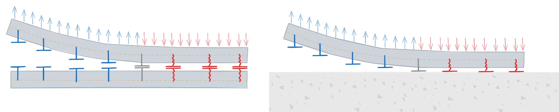
The "Contact relationship" function allows you to simulate contact between steel surfaces or between steel surfaces and concrete elements.

Entering contact details
To define contact relationships between surfaces, click on the “Contact relationship” option in the top toolbar.
Next, the two elements involved in the connection are selected, and the parts of each that are in contact are indicated.
Connections can be defined between steel surfaces or between steel surfaces and concrete elements.
Contact relationships are represented in the 3D view of the layout by a green surface located between the elements selected in the operation.
| Note: |
|---|
| Where bolt connections between two elements have been defined, these contact relationships are established automatically by the program, just as when a plate is joined to a concrete element using anchors. |
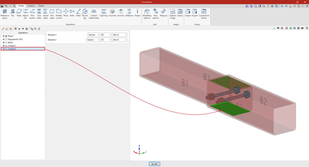
Contact between steel surfaces
In the relationships defined between steel surfaces, the elements involved in the relationship are selected in the "Element 1" and "Element 2" sections. These can be a “Section” or a “Plate”.
If a "Section" is selected, the part of the section involved in the connection is specified, such as the top flange ("Top flange"), the bottom flange ("Bottom flange"), the left web ("Left web"), or the right web ("Right web") of rectangular tube sections.
| Example: |
|---|
| In the example shown here, two tubular bars with different cross-sections have been defined, adjusted so that one is embedded inside the other. Next, the contact relationships between the surfaces of both bars are defined: 1. In the first step, the contact between the “Top flange” of both sections is defined using the various drop-down menus available. 2. You can then copy this operation and, whilst retaining the rest of the data, select the “Bottom flange” of both sections to define their contact. Once the model is complete, you can continue by opening the “Analysis” tab to perform the analysis of the connection. |
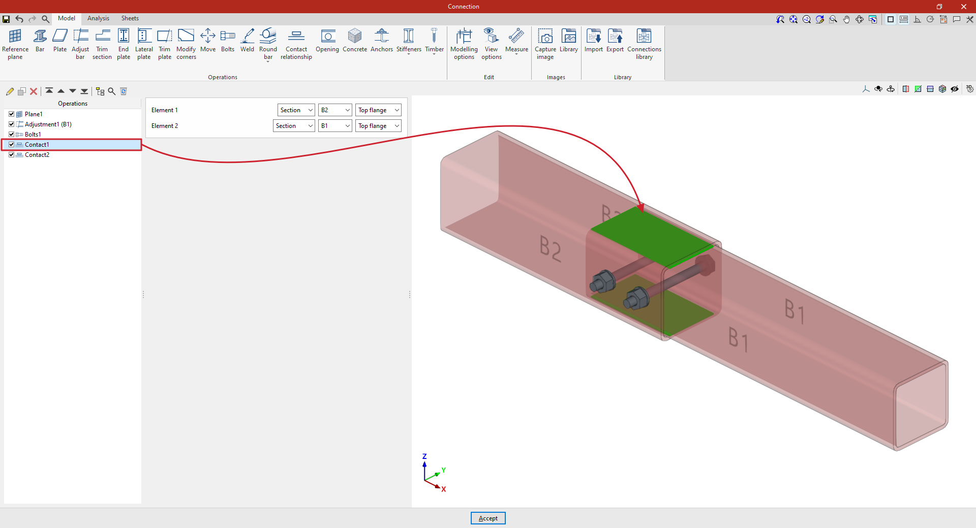
Contact surfaces between two steel profiles
Contact with concrete surfaces
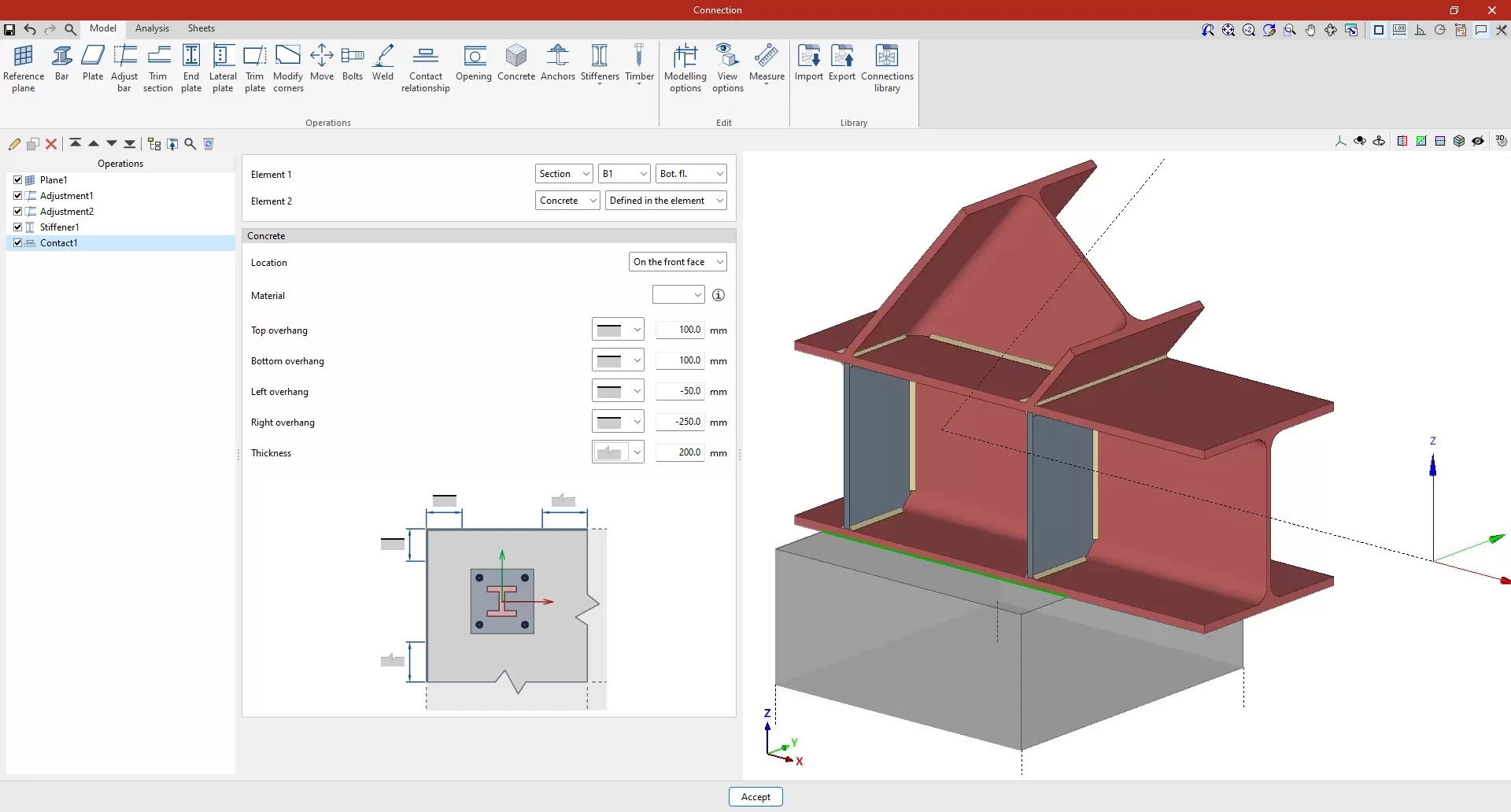
You can define a contact between a steel surface and the surface of a concrete element. To do this, select “Concrete” in the “Element 2” section.
The concrete element can be a new element defined in this operation, if "Defined in the element" is selected, or an existing element, in which case "Selection" must be chosen.
If "Defined in the element" is selected, the following parameters must be specified:
- The "Location" of the concrete element, whether "On the front face" or "On the back face" of the contact interface
- The element’s “Material”, which can be selected from those available
- The geometry of the element, defined by the values for "Top overhang", "Bottom overhang", "Left overhang", "Right overhang" and "Thickness", measured from the contour of the contact surface. For each of these, you must indicate whether or not the concrete element extends beyond the specified values by selecting the corresponding option from the drop-down menu.
"Opening" function
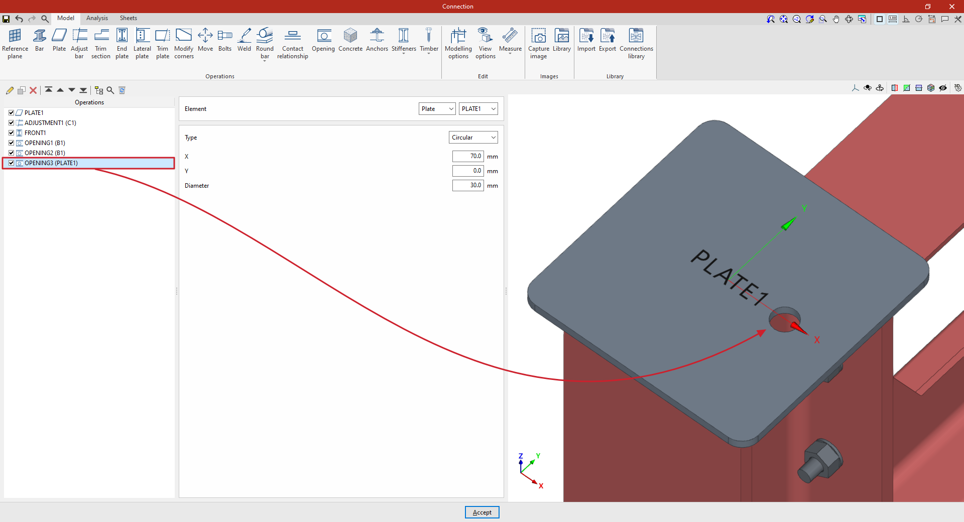
The "Opening" function allows you to create openings in sections or plates – whether circular, rectangular or polygonal – as well as to insert holes.

Inserting openings
To insert openings, click on the “Opening” option in the top toolbar.
First, select the “Element” where the opening is to be located, which can be a “Section” or a “Plate”. If a section is selected, you must select the plate or part of the section where you wish to create the opening, such as the top flange (“Top flange”), the bottom flange (“Bottom flange”) or the “Web” of rolled I sections.
The opening “Type” can be “Circular”, “Rectangular”, “Polygonal” or “Hole”:
Circular openings
To insert circular openings, select “Circular” under “Type”.
To position a circular opening, enter the ‘X’ and ‘Y’ coordinates of the opening’s centre relative to the element’s local coordinate system. Finally, enter the "Diameter" of the opening.
Rectangular openings
To insert rectangular openings, select “Rectangular” under “Type”.
You must define the local X and Y coordinates and the angle of the positioning origin for the openings in the element by entering this data in the "Origin: X / Y / Angle" fields.
Next, you must specify the “Width X” and “Width Y” of the opening.
In the diagram below, you can select the reference point for the opening: either its centre, the centre of one of its sides, or one of its corners.
Polygonal openings
To insert circular openings, select “Polygonal” under “Type”.
For polygonal openings, a table appears in which the geometry of the opening is defined:
- The options on the top bar allow you to “Add”, “Copy”, “Delete” and reorder vertices in the list. You can click “Add” several times to enter the “X” and “Y” coordinates of the vertices that form the opening’s polygon.
- The polygon may include straight or curved sections:
- If it is a straight section, select "Straight segment" in the "Type" column and define the "X" and "Y" coordinates of the starting vertex. The section will extend to the "X" and "Y" coordinates of the next vertex.
- If the section is curved, select "Curved segment" in the "Type" column and define the coordinates of the centre of the arc, "Xc" and "Yc". The section will extend from the "X" and "Y" coordinates defined for it to the "X" and "Y" coordinates of the next vertex.
To make it easier to enter this data, the program displays a "Help" image when you click on the relevant button at the top of the table.
| Note: |
|---|
| Right-clicking on the cells in this table gives you access to additional features, such as "Paste from the clipboard", which allows you to enter data quickly if it has already been entered into a spreadsheet. |
The program also features a "Generate" tool at the top of the list, which allows you to automatically generate vertices for polygonal openings in straight segments by entering the "Number of sides" and the "Radius" of the circle circumscribed around the vertices of the opening. Using this tool will clear any data previously entered in the list.
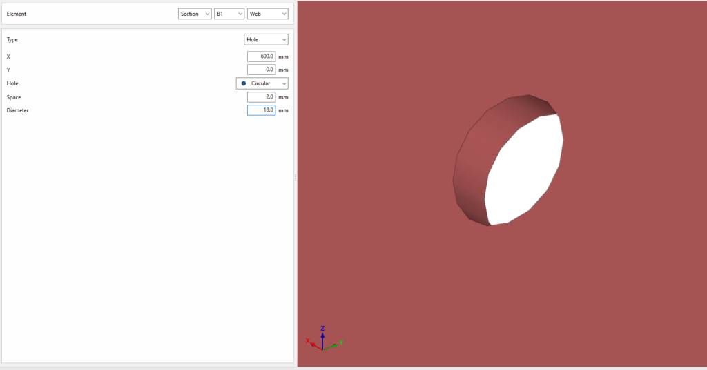
Hole
To add holes, select “Hole” under “Type”.
To position the hole, enter the "X" and "Y" coordinates of the hole centre relative to the part’s local coordinate system. Then select the type. This can be "Circular" or "Elongated":
- If it is "Circular", a "Space" is defined between the drill and the component passing through it, in addition to the "Diameter".
- The hole can be "Elongated" in either of the two local directions (X or Y) on the sheet metal. In this case, the ratio between the length and the diameter of the hole ("L/d") is defined, where 1 corresponds to a circle, as well as the "Space" between the hole and the through-part and its "Diameter".
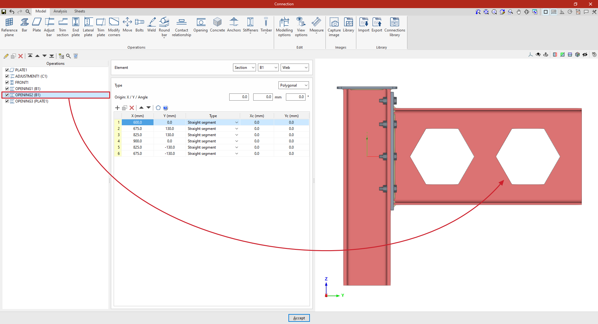
Example
In this example, a plate has been inserted at the top of the column, and its geometry has subsequently been adjusted. A front plate has also been added to connect beam B1 and column C1.
Next, the necessary welds are made between the beam sections and between the plate and the beams.
Next, openings are cut into the beam to simulate a lightened web:
1. Select the “Section” B1 and choose the “Web”. In this case, the opening takes on a hexagonal shape, so select “Polygonal” and enter its coordinates in the table.
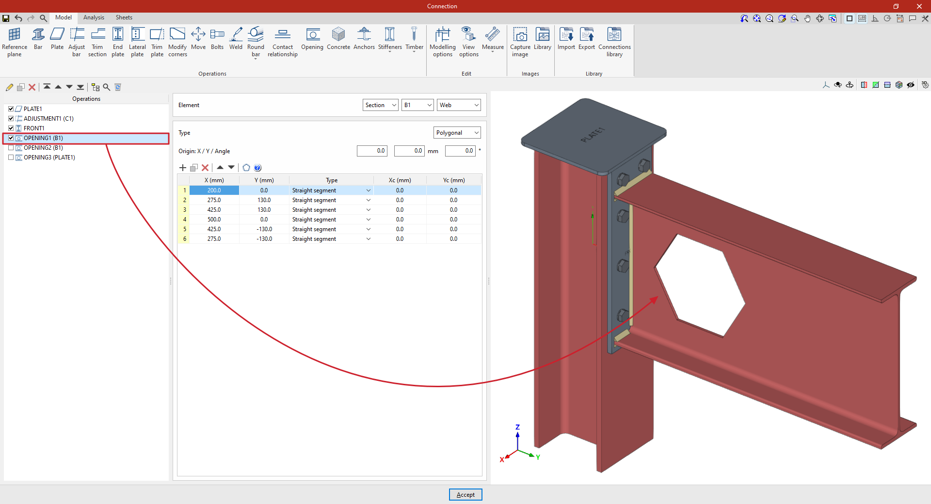
2. Further along, a second opening is cut into the beam.
To do this, copy the previous transaction by selecting it in the table on the left and clicking the “Copy” button at the top.
Next, whilst retaining the rest of the data, enter the coordinates of the new opening to position it correctly. The values can be typed directly into the cells or pasted from the clipboard.
3. To create an opening in the plate, click on the “Opening” option again and, in the “Element” section, select “Plate” 1 from the drop-down menu.
At this point, once the model is complete, you can continue by opening the “Analysis” tab to perform the analysis of the connection.
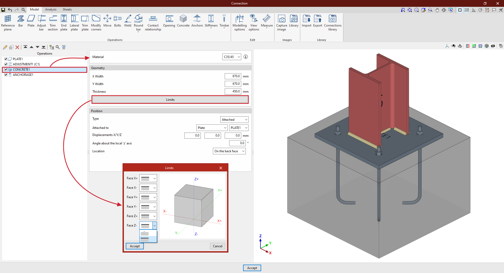
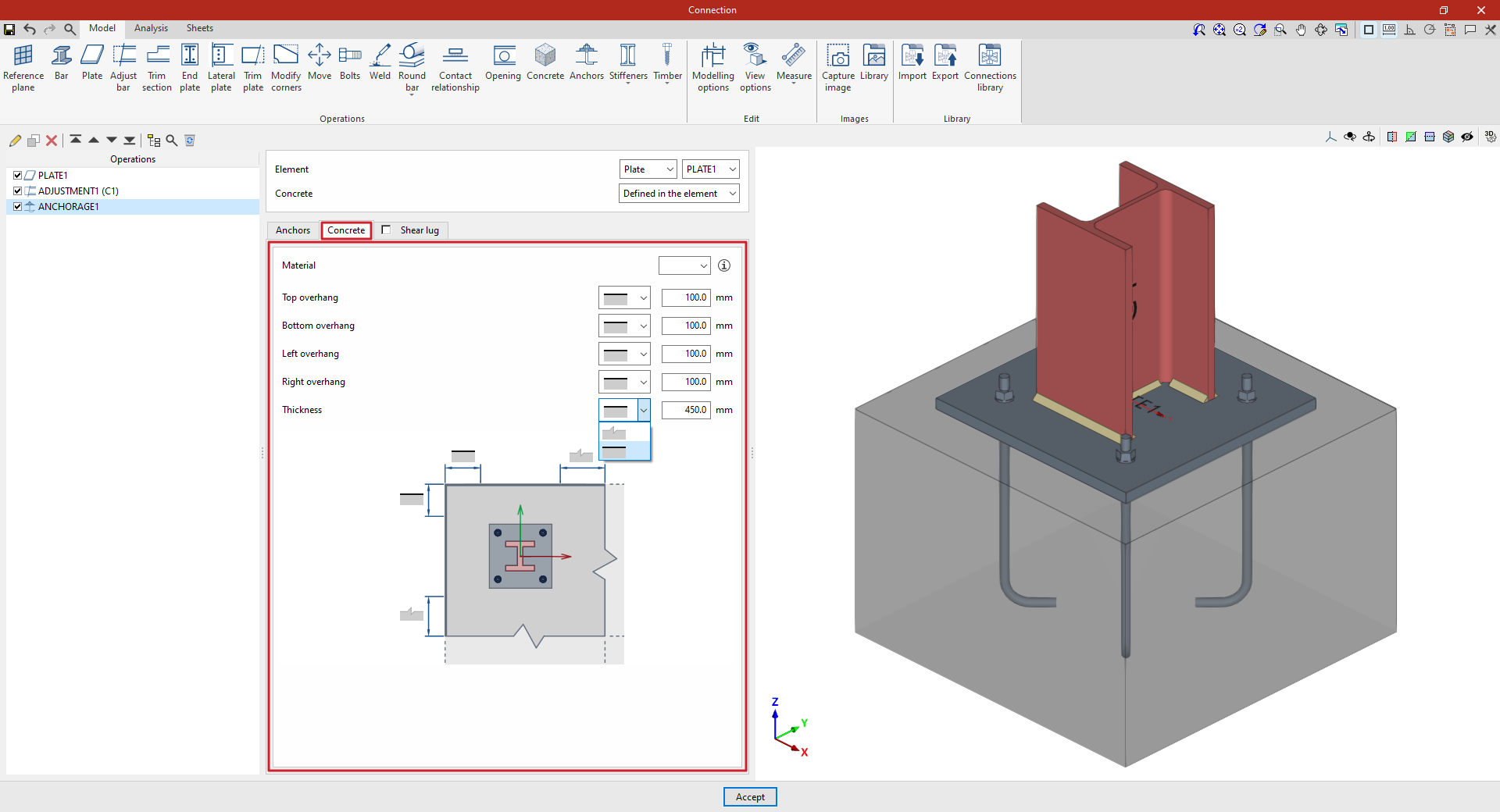
"Concrete" function
The "Concrete" operation allows concrete elements to be inserted into the connection. Anchors will be fitted to these, if necessary.

Inserting concrete elements
To insert a concrete element, click on the “Concrete” option in the top toolbar.
| Example: |
|---|
| In this example, a plate has been added to the base of column C1, and an adjustment operation has been performed on it to modify its geometry and insert the welds between the section and the plate. Next, a concrete element is inserted so that the connections between the plate and the concrete can be defined later. In this case, select “Attached” to “Plate” and choose the plate inserted from the corresponding drop-down menu. The “Location” of the element is “On the back face” From this point onwards, once the concrete element has been added, it can be selected in subsequent operations, such as “Anchors” Once the model is complete, you can continue by opening the “Analysis” tab to perform the analysis of the connection. |
Choice of material
First, specify the “Material” by selecting it from the drop-down menu of available concrete options.
By clicking on the button on the right, you can view information such as the “Reference” or the “Compressive strength” of the selected concrete.
Definition of the geometry of the concrete element
Next, define the “Geometry” of the concrete volume by entering the “Width X”, “Width Y” and “Thickness”.
By clicking the "Boundaries" button, you can use a series of drop-down menus to specify whether the element extends beyond each of the six faces of the concrete element in the model ("Face X+", "Face X-", "Face Y+", "Face Y-", "Face Z+" and "Face Z-") or whether these correspond to the element’s actual boundaries.
Definition of the position of the concrete element
To define the element’s “Position”, select either “Connection”, “Attached” or “Perpendicular” from the “Type” drop-down menu:
- In the “Type” drop-down menu, select “Connection” if you wish to define the position of the element by entering the “X”, “Y” and “Z” coordinates relative to the centre of the connection.
If you need to rotate the concrete element, you can enter the “Angle about the local ‘x’ axis”, the “Angle about the local ‘y’ axis” and the “Angle about the local‘Z’ axis”.
- In the “Type” drop-down menu, you can also select “Attached” or “Perpendicular” to indicate that the concrete element is attached to or perpendicular to a “Plate”, a “Bar” or a “Reference plane”
You can enter “X/Y/Z displacements”, if desired, as well as an “Angle about the local ‘z’ axis”
Finally, specify the “Location” of the element, which can be “On the front face” or “On the back face” of the element to which it is attached or perpendicular.
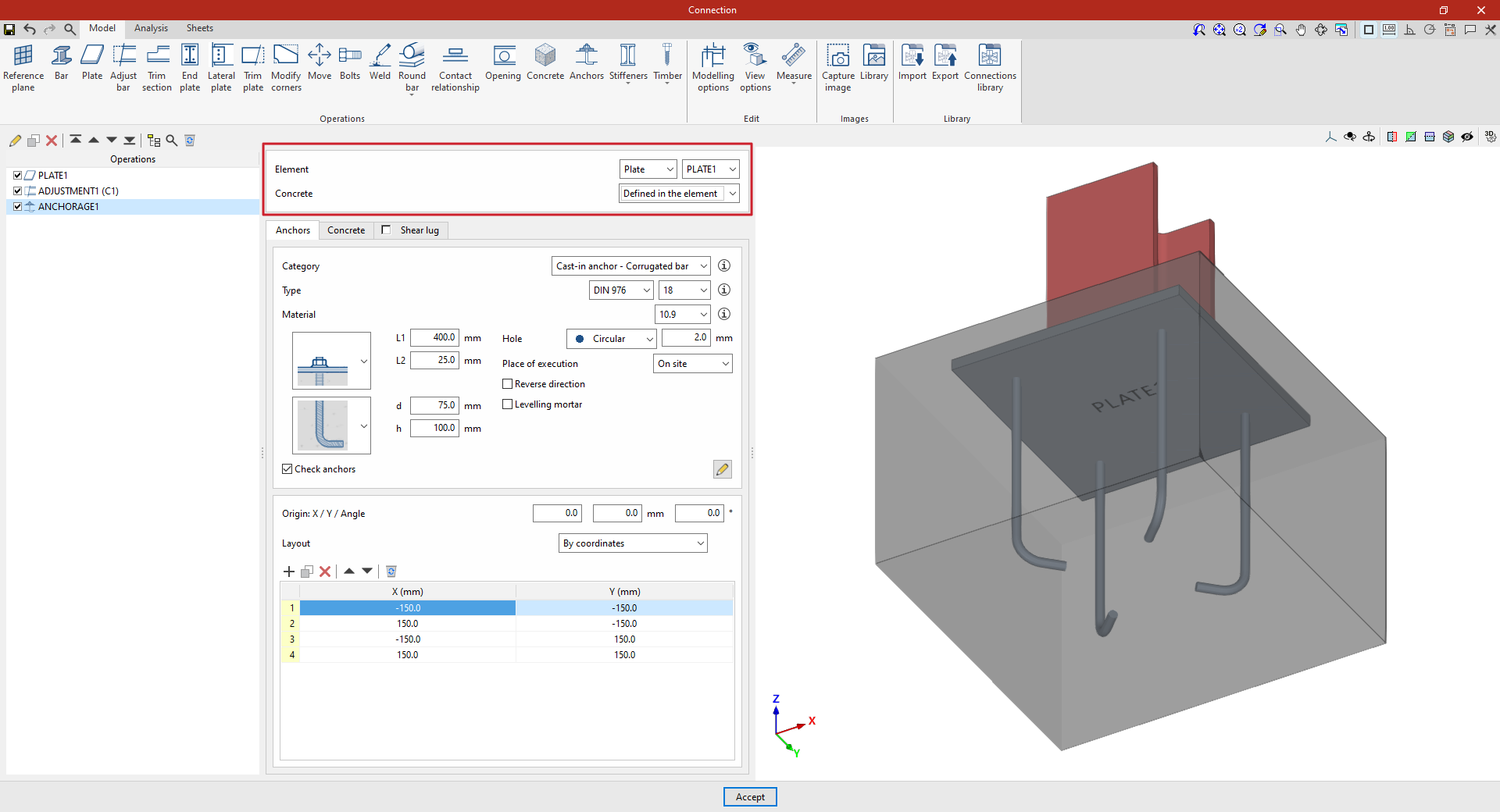
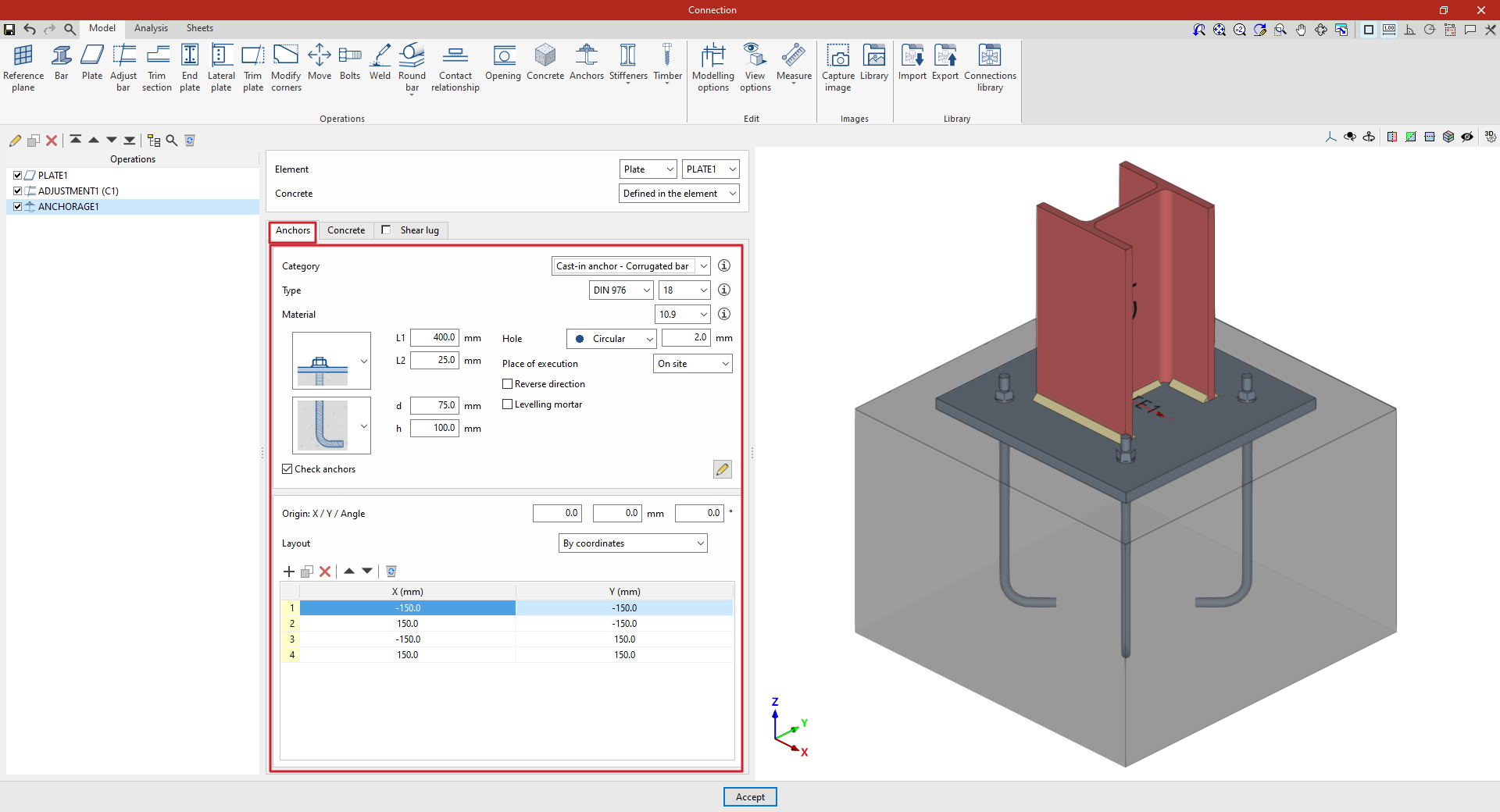
"Anchors" function
The "Anchors" function is used once an element, such as a plate or a section, has been inserted, and allows you to add anchors to it.

Anchors are installed in the same way as bolts. In addition, shear lugs can be inserted to transfer shear forces to the foundation element.
Inserting anchors
To insert anchors, click on the “Anchors” option in the top toolbar.
First, select the "Element" where the anchors are to be defined; this can be a "Plate" or a "Section". If you select a section, you must then select the plate or part of the section where you wish to insert the anchors.
Next, you decide whether the “Concrete” is “Defined in the element” or whether you wish to “Select” a concrete element entered via a separate operation.
Defining anchors
In the "Anchors" tab, you can configure and position the anchors:
| Example: |
|---|
| In the example shown here, a plate has been added to the base of column C1, and an adjustment operation has been performed on it to modify its geometry and insert the welds between the section and the plate. Next, the anchors are added to create the connection between the plate and the foundation concrete. In this case, select “Plate” and choose the plate available from the drop-down menu on the right. To manually define the position of the anchors, click on “Add” and enter the “X” and “Y” coordinates relative to the element’s local coordinate system. |
Anchor configuration
First, the following parameters are defined:
- You must select the anchor's "Category" from the following:
- "Cast-in anchor – Corrugated bar",
- "Cast-in anchor – Threaded rod",
- "Cast-in anchor – Smooth bar",
- or "Cast-in anchor".
- Further down, you can select the “Type” of anchor, choosing its series and nominal diameter from those available. If you wish, you can click on the button on the right to open a window where you can view details such as the following:
- For the “Bolt”, the series reference, the “Nominal diameter” and the “Diameter of the thread” are shown.
- In the case of the “Nut” and the “Washer”, the series codes and nominal diameter are also given, along with the “Outer diameter”, “Inner diameter” and “Thickness” of each.
- Next, select the “Material” of the anchor. By clicking on the button on the right, you can view its properties, including its “Reference”, “Modulus of elasticity”, “Yield strength” and “Fracture limit”, as well as the material of the “Nut” and the “Washer”.
Two drop-down menus then appear to allow you to select the type of anchor. These drop-down menus vary depending on the selected anchor "Category".
For example, in pre-installed rebar anchors:
- In the first drop-down menu, select the type of connection between the bolt and the plate, which can be flush-mounted with a washer and single nut, flush-mounted with a welded bolt, spaced, or spaced with a nut and washer.
- The second drop-down menu allows you to select the type of concrete anchor, which can be a straight extension, with a washer and single nut, with a double nut, with a 180-degree hook, or with a 90-degree bend.
The program asks you to define the parameters corresponding to various geometric dimensions, such as “Ln”, “L1”, “L2”, “d” or “h”. To make it easier to enter this data, a help image is available via the button to the right of the “Category” drop-down menu.
On the right, you can specify the following additional parameters:
- The anchor's "Hole" is defined later on. This can be:
- "Circular", in which case a "Space" is defined between the drill bit and the anchor
- Or "Elongated" in either of the two local directions (X or Y) of the sheet metal. In this case, the ratio between the length and the diameter of the hole ("L/d") is defined, with a value of 1 corresponding to a circle, as well as the "Space" between the hole and the anchor
- The drop-down menu below allows you to select the "Location", either "On site" or "At workshop".
- The "Reverse direction" checkbox can be ticked to change the orientation of the anchors.
- It is also possible to apply a layer of “Levelling mortar” between the element and the concrete, specifying its thickness.
Finally, the "Check anchors" checkbox can be ticked to enable the program to carry out checks on these elements. The button on the right opens a pop-up window where you can configure the parameters and factors to be taken into account in these checks.
Layout of the anchors
The following section then specifies the number and layout of the anchors:
- You must define the local X and Y coordinates and the angle of the positioning origin for the anchors on the plate or bar by entering this data in the "Origin: X / Y / Angle" fields.
- Below, it is indicated whether the "Layout" of the anchors on the plate or bar is:
- "By coordinates",
- By "Rows and columns",
- By "Rows and columns per flange" (in front plates on rolled I sections),
- "Perimeter" on the sheet metal,
- Or "Radial".
| More information: |
|---|
| Further information on these layout options can be found via the link below. |
Defining a concrete element
The “Concrete” tab allows you to define the concrete element of the anchor in this same operation and appears if this has been specified previously (by selecting “Defined in the element” in the “Concrete” section).
First, specify the “Material” by selecting it from the concrete options available in the project. The button on the right allows you to view the parameters of the selected concrete, such as the “Reference” or the “Compression resistance”.
Finally, the geometry of the concrete volume is defined using the values for the "Top edge", "Bottom edge", "Left edge", "Right edge" and "Thickness", measured from the outline of the selected slab. For each of these, you must indicate whether the concrete element is limited to these values or extends beyond them by selecting the corresponding option from the drop-down menu.
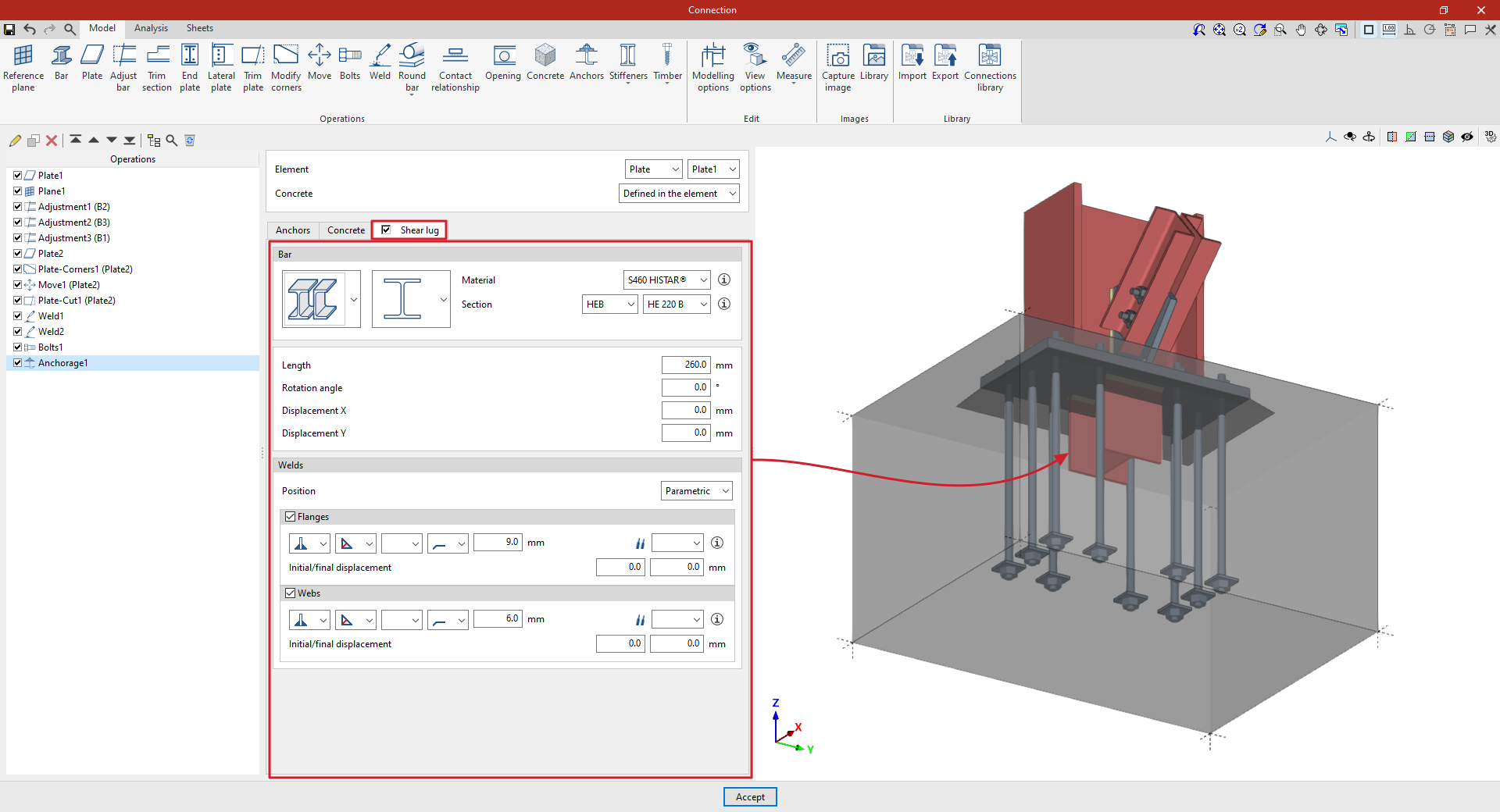
Inserting and defining shear lugs
Shear keys are steel sections welded to the underside of an anchor plate and embedded in the concrete; they allow shear forces to be transmitted directly to the foundation element, thereby freeing the anchor bolts to act solely in tension.
Shear keys can be defined for the anchor plates entered in the program. To do this, in the "Anchors" operation, tick the “Shear lug” box in the relevant tab.
| Example: |
|---|
| In the example shown here, a plate has been added to the base of the column, adjustments have been made to the geometry of the sections, and another plate has been inserted and adjusted to form the connection between them, together with the necessary welds and bolts. Finally, an anchoring operation has been inserted by selecting the first plate, thereby indicating that it is a baseplate on the concrete of the foundation element. Furthermore, angle weld beads have been defined, specifying the thicknesses of the grooves. |
Selecting the bar, material and section of the shear lugs
To define the cutting tool, you must first specify the “Bar” parameters, such as its type, and select the “Material” and “Cross-section” from those available in the library, which can be configured in advance via the relevant option in the main interface.
Defining the geometry and position of the shear lug
Next, its geometric properties are defined, such as the “Length” of the shear lug from the plate, the “Rotation angle”, as well as the “X displacement” and “Y displacement” relative to the element’s local axes.
Defining shear lug welds
Next, the “Welds” between the baseplate and the shear lug are defined. The “Position” of the weld can be “Perimeter”, encircling the entire section, or “Parametric”. In this case, the welds on the “Flanges” and the “Web” are defined.
Within each section, the drop-down menus display various options for specifying the position of the weld, the type of weld, the shape of its surface and the location where it is to be carried out, either on-site or at a workshop.
You can also select the “Electrode” and specify whether the welds have an “Initial displacement” or a “Final displacement”.
At this point, once the model is complete, you can continue by opening the “Analysis” tab to perform the analysis of the connection.
| Note: |
|---|
| The strength of the concrete element for shear lugs is verified by testing the compressive strength on the faces of the shear lug. |
Operation "Stiffeners": web stiffeners
The "Stiffeners" operation is used to insert stiffeners via a wizard in which their material, geometry, position and welds are defined.

Stiffeners can be inserted into the web of a section or into a plate.
Installation of web stiffeners
To insert web stiffeners, click on the “Stiffeners” option in the top toolbar to open the menu, then select “Web”.
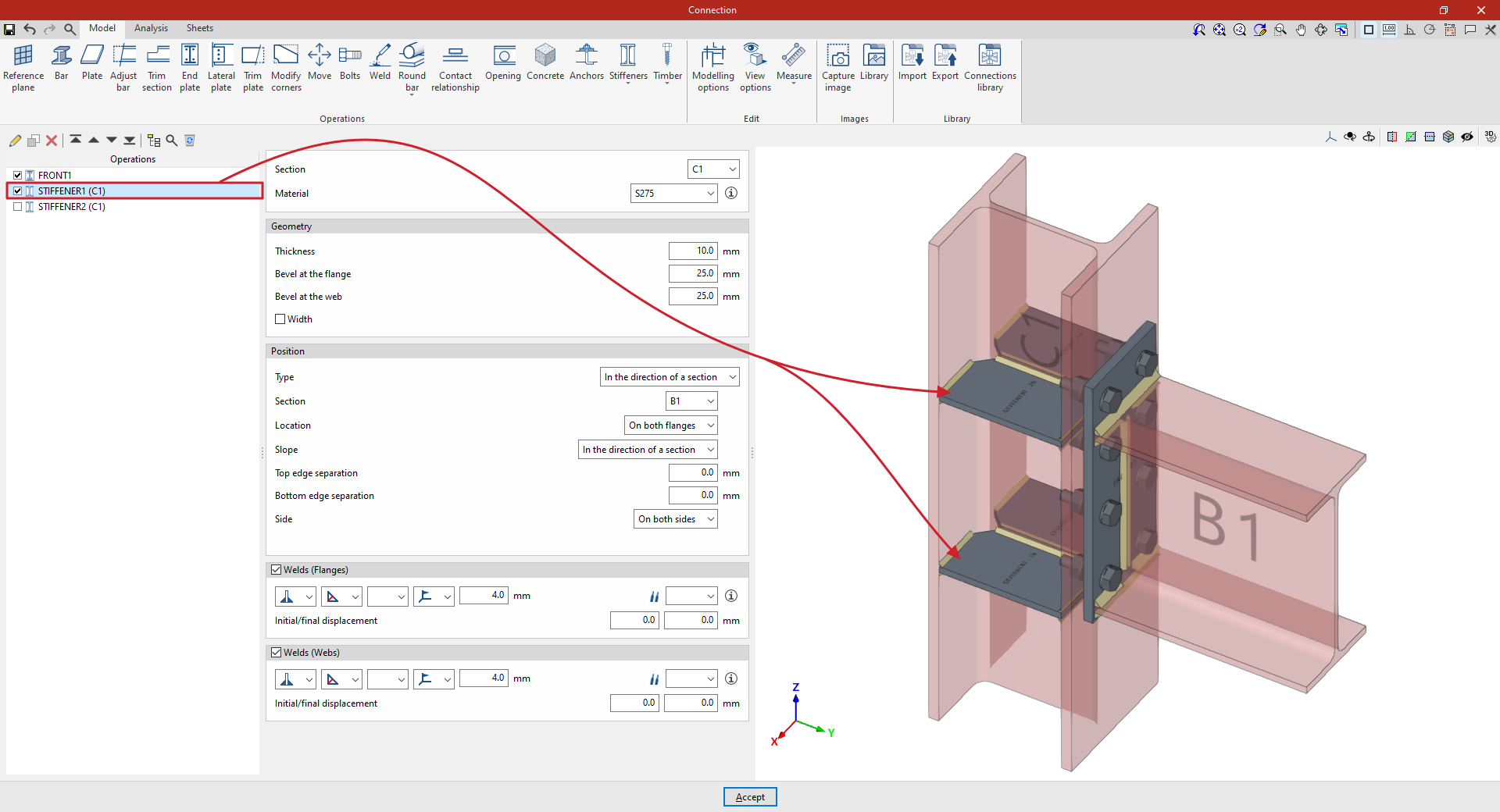
| Example: |
|---|
| In the example shown here, which illustrates a connection between a column and a beam, a flange has been added to connect the beam to the column. Next, stiffeners are added to the column to improve the performance of the connection. The first set of stiffeners is located on column C1, in the direction of beam B1. Angle welds are defined using the throat depth, with a dimension of 4 millimetres. The second set of stiffeners is located on column C1 in an upper position, independent of the beam’s position. In the “Position” section, “Local” is selected in this case, and the necessary parameters are specified. From here, once the model is complete, users can continue by opening the “Analysis” tab to perform the analysis of the connection. |
Selecting the section and material for the stiffeners
First, select the “Section” where the stiffeners are located.
Next, select the “Material” for the stiffeners from the drop-down menu.
If you click on the button on the right, you can view the “Reference” and properties of the selected material, such as the “Modulus of elasticity”, “Poisson’s ratio”, “Coefficient of thermal expansion”, “Specific weight”, “Yield strength” and “Fracture limit”. In addition, the “Resistance depending on the thickness” is shown.
Defining the geometry of the stiffeners
The following section allows you to define the “Geometry” of the stiffeners.
Here, you enter the values for “Thickness”, “Bevel at the flange” and “Bevel at the web”.
Optionally, you can tick the relevant box to indicate that the “Width” of the stiffeners is different from that of the section in which they are located.
Specifying stiffener welds
If required, the welds connecting the stiffener to the flanges and webs of the section can be defined directly by ticking the boxes in the relevant sections at the bottom of the panel (“Welds (Flanges)” and “Welds (Webs)”).
Within each section, the drop-down menus display various options for specifying the position of the weld, the type of weld, the shape of its surface and the location where it is to be carried out, either on-site or at a workshop.
It is also possible to select the “Electrode” and specify whether the welds have an initial displacement or a final displacement (“Initial/final displacement”). By default, the program places the weld on the flat part of the web, interrupting the weld bead at the radius specified in the section.
Defining the position of the stiffeners
The "Position" section defines the position of the stiffeners.
In the “Type” drop-down menu, select “Local” or “In the direction of a section”:
Stiffeners along the length of a section
In this case, the stiffeners follow the path of a specific “Section”, which must be selected from the drop-down menu.
Next, the “Location” of the stiffeners is configured. This can be on the “Top flange”, the “Bottom flange”, “On both flanges” or the “Centre”.
On the other hand, the “Slope” can be “Local” or defined “In the direction of a section” (i.e. in the direction of the previously selected section).
To adjust the geometry of the stiffener, you can also enter a “Top edge separation” and a “Bottom edge separation”.
Below, it is indicated whether the stiffeners are located on the “Left”, “Right” or “Both sides” of the section.
Local stiffeners
To add stiffeners to a bar at any position, select “Local” in the “Position” section. This allows you to specify the position of the stiffener freely, without being constrained by the geometry of another bar.
To do this, enter the value for “X displacement”, which follows the section’s local X-axis.
You must also specify the “Slope” of the stiffener by entering its value in degrees.
Next, as in the previous case, enter the “Top edge separation” and the “Bottom edge separation”, and specify the “Side” of the section where the stiffeners are to be placed, whether “Left”, “Right” or “On both sides”.
Finally, the “Number of stiffeners” is specified; this may be one or more, in which case the “Spacing” between them is also stated.
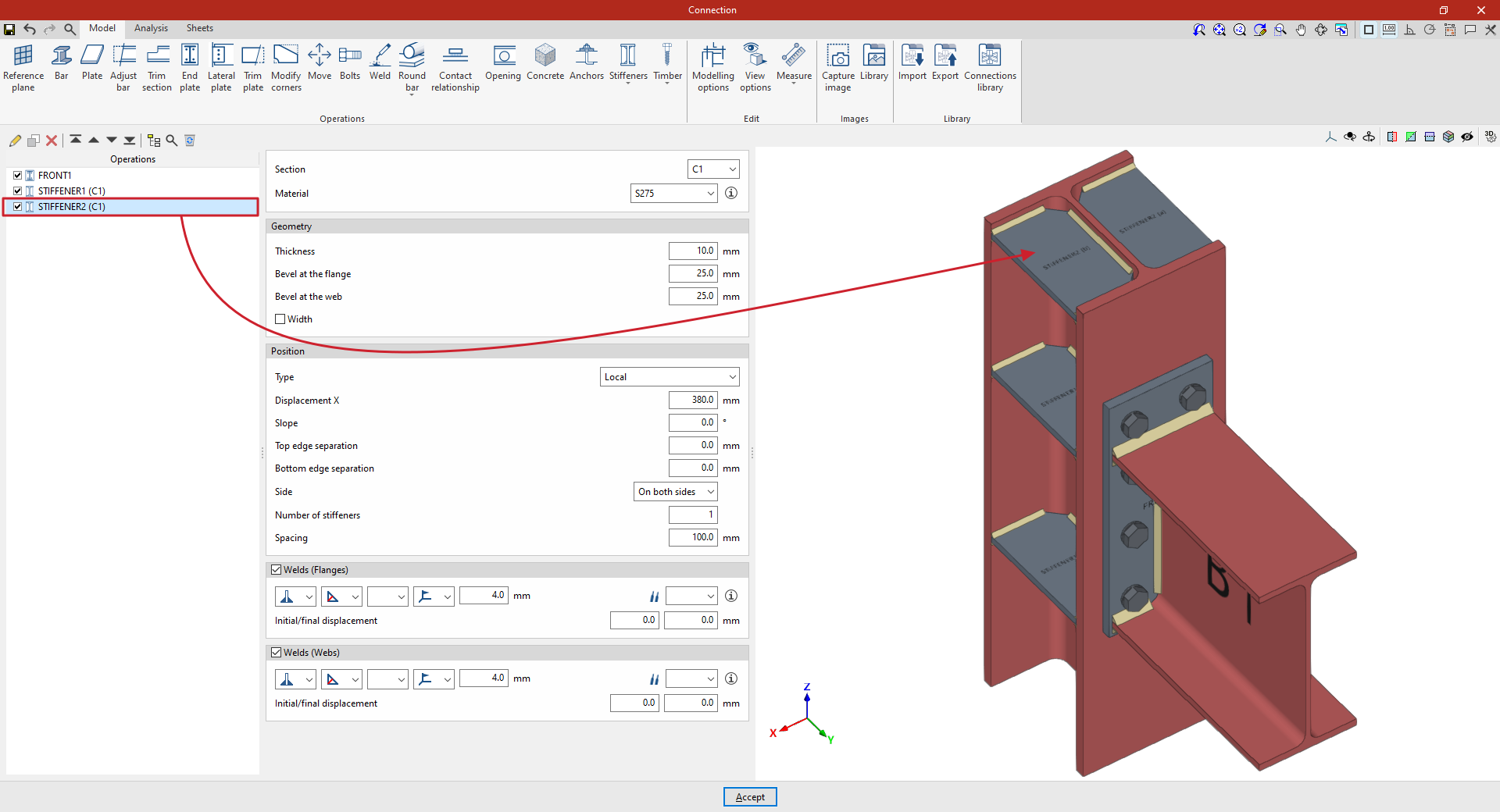
"Stiffeners" function: plate stiffeners
The "Stiffeners" operation is used to insert stiffeners via a wizard in which their material, geometry, position and welds are defined.
Stiffeners can be inserted into the web of a section or into a plate.
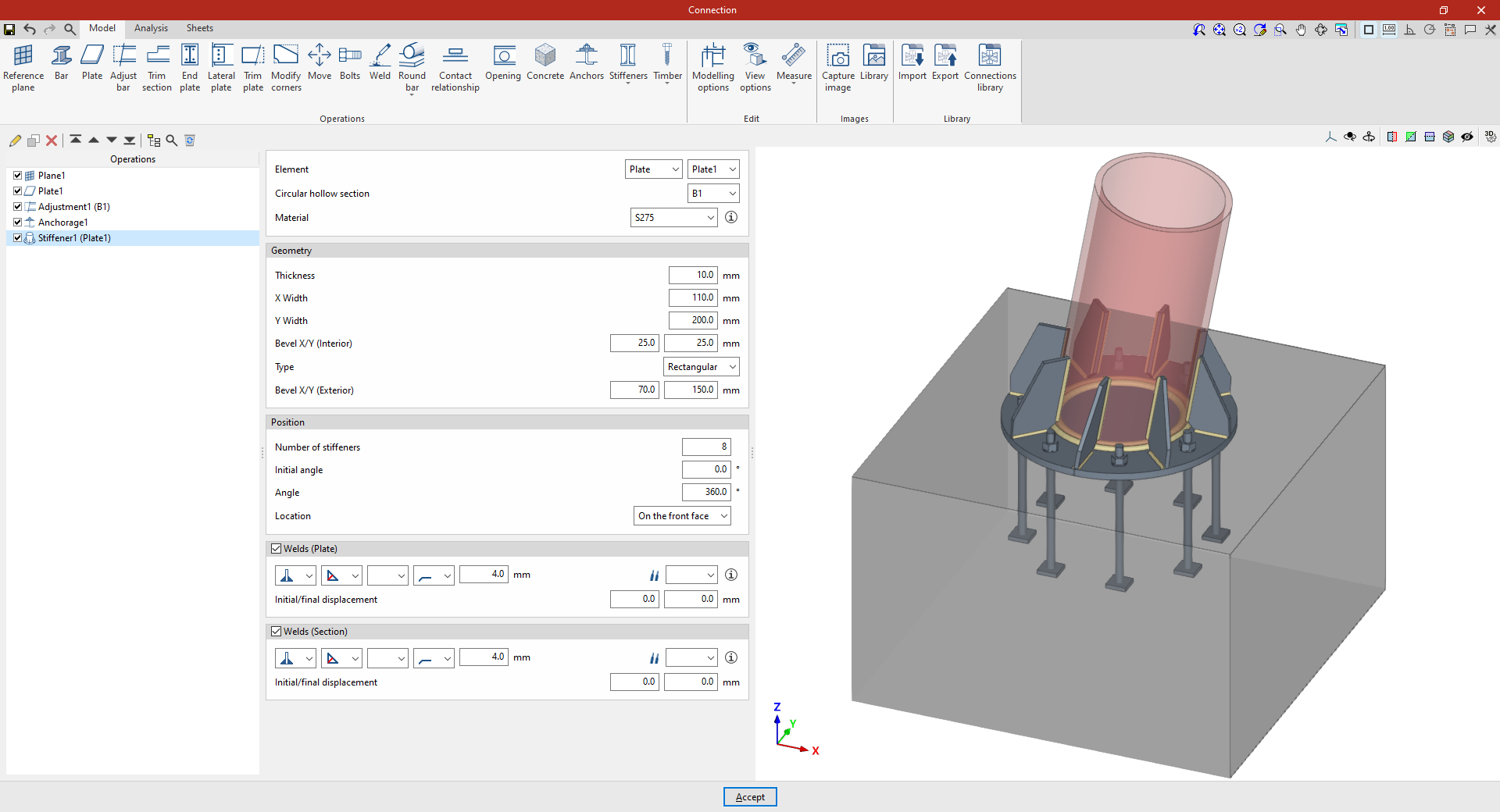
| Example: |
|---|
| In the example shown here, stiffeners are added between a plate and a circular hollow section. A plate has already been added to the base of the circular column, its geometry has been adjusted, and the anchor bolts have been defined on the foundation element. Next, stiffeners are added to the plate to improve its performance. |
Inserting plate stiffeners
Stiffeners can be inserted between a plate and a circular hollow section. To do this, click on the “Stiffeners” option in the top toolbar and select “Plate”.
Selecting the plate and the circular hollow section
First, specify the “Element” where the stiffeners are located – either a “Plate” or a “Section” – and select the corresponding “Circular hollow section”.
The stiffeners are arranged radially around the selected circular hollow section and parallel to the axis of the section.
Defining the geometry of the stiffeners
Next, the "Geometry" of the stiffeners is defined. This includes:
- Its “Thickness”,
- “Width X” and “Width Y” in the directions radial and perpendicular to the plate,
- The dimensions of the inner bevel ("Bevel X/Y (Inner)"),
- The “Type” of stiffener, either “Triangular” or “Rectangular”,
- And, in the case of rectangular stiffeners, the dimensions of the outer chamfer (“Chamfer X/Y (Outer)”).
Defining the position of the stiffeners
As regards the “Position” of the stiffeners, it should be noted that:
- The “Number of stiffeners” to be provided,
- The “Initial angle” at which the first one is located, measured from the position of the section’s local Y-axis,
- And the total “Angle” covered by the assembly, over which the stiffeners are distributed evenly;
- The “Location” of the stiffeners can be “On the front face” of the plate, “On the back face” or “On both faces”.
Defining the stiffener welds
Next, the “Welds” between the stiffeners and the “Plate”, and between the stiffeners and the “Section, are defined.
Within each section, the drop-down menus offer various options for specifying the position of the weld, the type of weld, the shape of the weld surface and the location where the work is to be carried out, either on-site or at a workshop.
You can also select the “Electrode” and specify whether the welds have an “Initial displacement” or “Final displacement”.
From here, once the model has been completed, users can continue by opening the “Analysis” tab to carry out the analysis of the connection.
"Timber" functions: dowels
The "Timber" operation is used to insert fasteners into timber bars.

The fasteners available for timber include dowels, bolts and screws.
| Note: |
|---|
| This feature is only available in CYPE Connect. |
Inserting dowels
To insert dowels, open the “Timber” menu in the top toolbar and click on the “Dowels” option.
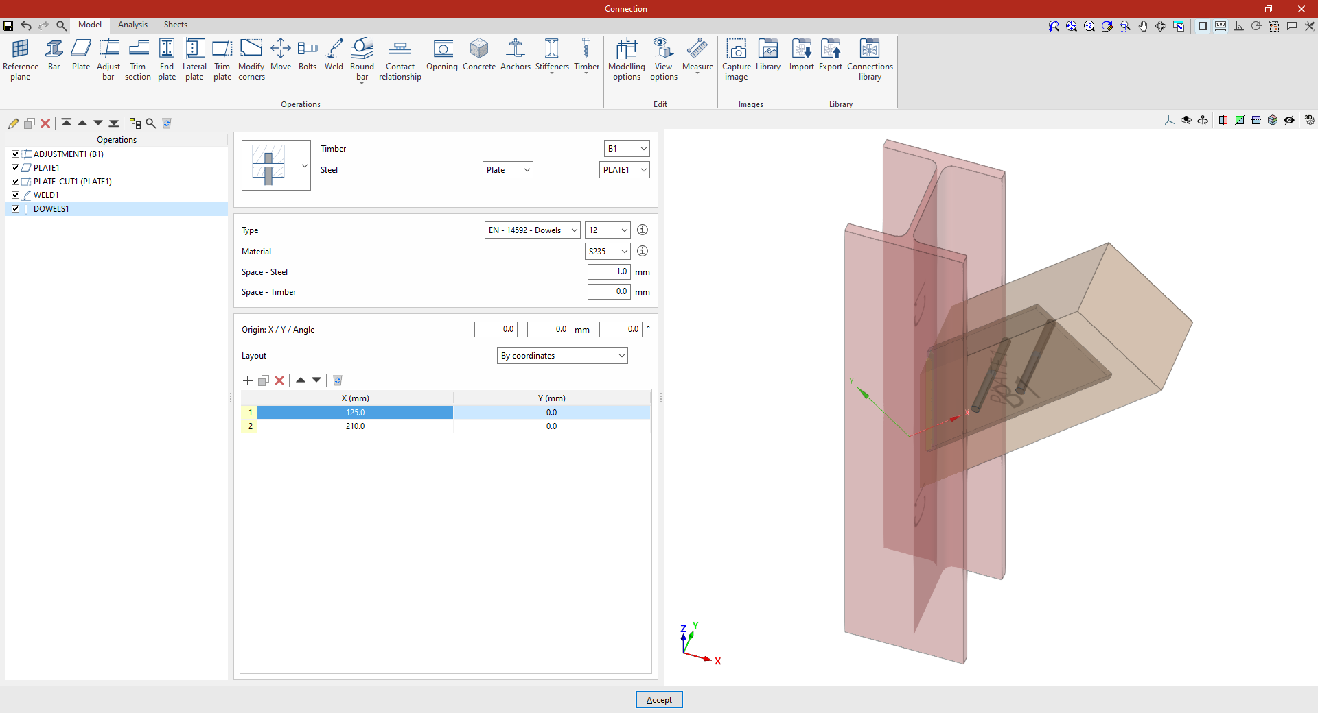
| Example: |
|---|
| In this example, a connection between a steel component and a timber element is solved. Previously, a restraint was applied to the timber beam B1, and a welded plate was added to the steel column C1. Next, the dowels that solve the connection between plate 1 and the timber beam B1 are inserted. |
Selecting the parts
In the first drop-down menu, select whether the pin connects a single piece of timber to a steel component or two different pieces of timber to an intermediate steel component.
Next, on the right, select the “Timber” component and the “Steel” component from those available, whether a “Section” or a “Plate”.
Dowel configuration
Next, you need to specify the “Type” of dowel. Using the drop-down menus on the right, you can select the “Series” and “Diameter” from the available options.
The button on the right allows you to view the “Series” and “Nominal diameter”, as well as the “Shaft diameter” and “Available lengths”.
The following section specifies the “Material” of the dowel. Similarly, by clicking the button on the right, you can view the material’s properties, such as its “Reference”, “Description”, “Modulus of elasticity”, “Yield strength” and “Fracture limit”.
Finally, the space between the dowel and the steel component (“Space – Steel”) and the space between the dowel and the timber element (“Space – Timber”) are defined.
Positioning the dowels
Below is a table showing the number and position of the dowels.
- You must define the local X and Y coordinates and the angle of the positioning origin for the dowels on the plate or bar by entering this data in the "Origin: X / Y / Angle" fields.
- Below, it is indicated whether the "Layout" of the dowels on the plate or bar is:
- "By coordinates",
- By "Rows and columns",
- By "Rows and columns per flange" (in front plates on rolled I sections),
- "Perimeter" on the sheet metal,
- Or "Radial".
| More information: |
|---|
| More information on these layout options can be found via the following link. |
From here, once the model has been completed, users can continue by opening the “Analysis” tab to carry out the analysis of the connection.
"Timber" functions: bolts
The "Timber" function is used to insert fasteners into timber bars.
The fasteners available for timber include dowels, bolts and screws.
| Note: |
|---|
| This feature is only available in CYPE Connect. |
Inserting bolts
To insert dowels, open the “Timber” menu in the top toolbar and click on the “Bolts” option.
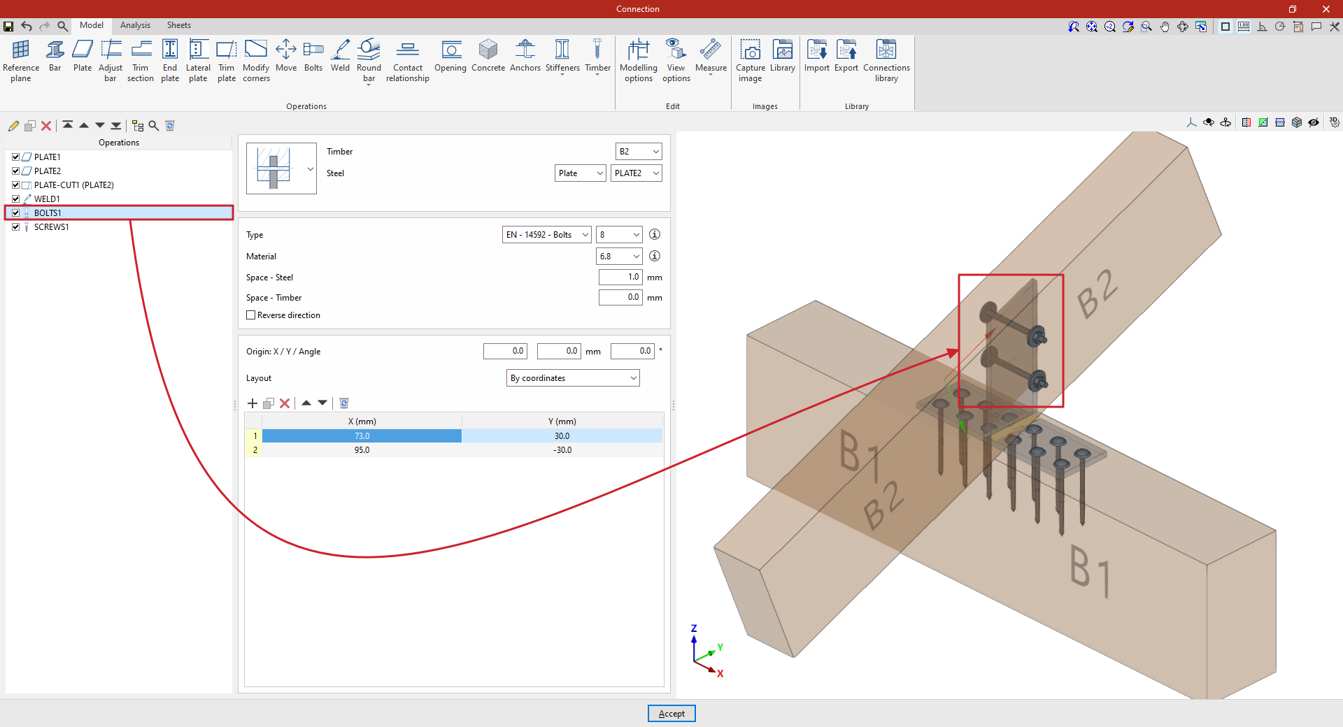
| Example: |
|---|
| In this example, the aim is to create a connection between two timber bars. First, a plate has been placed on the main beam B1. Next, a second plate has been added, positioned perpendicular to and welded to the first. Finally, bolts are inserted to create the connection between this plate and the secondary beam B2. |
Selecting the parts
In the first drop-down menu, you select whether the bolt connects a steel element and a timber element, two steel elements and an intermediate timber element, a single timber element and an intermediate steel element (as in this case), or two different timber elements and an intermediate steel element.
Next, on the right-hand side, select the “Timber” component and the “Steel” element from those available, whether a “Section” or a “Plate”. In this case, select beam B2 and plate 2.
Bolt configuration
Next, you need to specify the “Type” of bolt. Using the drop-down menus on the right, you can select the “Series” and “Diameter” from the available options.
After clicking “Accept”, you can click the button displaying the series name and diameter to modify these specifications, if required.
The button on the right allows you to view the following information:
- Firstly, the bolt’s "Series", "Nominal diameter", "Diameter of the thread", "Head diameter" and "Head thickness".
- The table then shows values indicating the “Length” of the bolt and the “Length of the threaded part”.
- The parameters for the “Nut” and the washers used in wooden and steel components (“Washer – Timber” and “Washer - Steel”), including the “Series” and “Nominal diameter” references, as well as the “Outer diameter”, “Inner diameter” and “Thickness” values for each component.
- It also specifies whether a “Locknut” is required on the bolt.
The following section specifies the bolt’s “Material”. Similarly, by clicking the button on the right, you can view the material’s properties, such as its “Reference”, “Description”, “Modulus of elasticity”, “Yield strength” and “Fracture limit”.
Later on, the space between the bolt and the steel component (“Space – Steel”) and the space between the bolt and the timber element (“Space – Timber”) are defined.
Finally, you can tick the last box to “Reverse the direction” of the bolt.
Positioning the bolts
Below is a table showing the number and position of the bolts.
- You must define the local X and Y coordinates and the angle of the positioning origin for the bolts on the plate or bar by entering this data in the "Origin: X / Y / Angle" fields.
- Below, it is indicated whether the "Layout" of the bolts on the plate or bar is:
- "By coordinates",
- By "Rows and columns",
- By "Rows and columns per flange" (in front plates on rolled I sections),
- "Perimeter" on the sheet metal,
- Or "Radial".
| More information: |
|---|
| More information on these layout options can be found via the following link. |
From this point onwards, the remaining operations required to complete the connection model must be added before the “Analysis” can be carried out.
"Timber" function: screws
The "Timber" operation is used to insert fasteners into timber bars.
The fasteners available for timber include dowels, bolts and screws.
| Note: |
|---|
| This feature is only available in CYPE Connect. |
Inserting screws
To insert screws, open the “Timber” menu in the top toolbar and click on the “Screws” option.
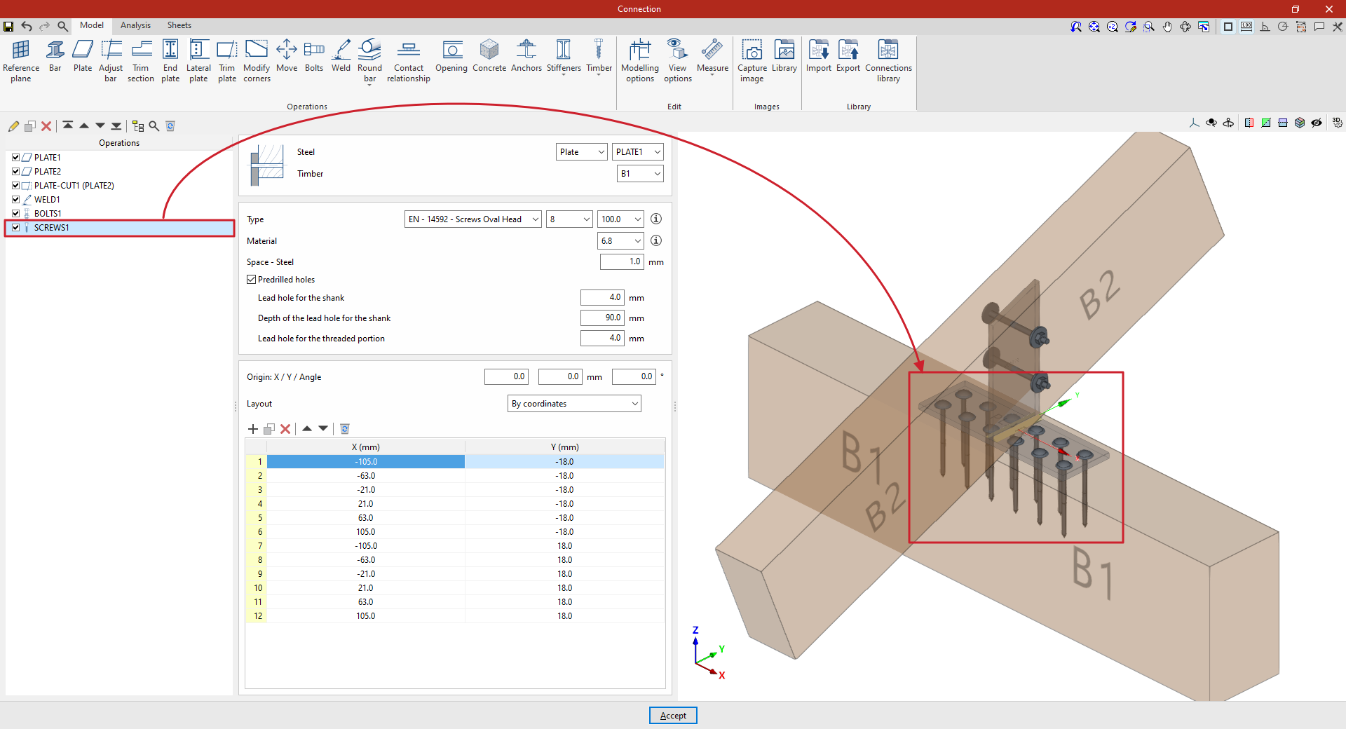
| Example: |
|---|
| In this example, we want to solve a connection between two timber elements. A plate has been placed on the main beam B1. A second plate has then been added, positioned perpendicular to and welded to the first, and bolted to beam B2. Next, the screws are added to create the connection between the first plate and the main beam B1. In this case, plate 1 is selected, along with the timber bar corresponding to beam B1. Two "Rows" and six "Columns" of screws are defined. Next, the initial spacing for the rows and columns is entered, as well as the spacing between rows and between columns. |
Selecting the parts
First, select the components that the screw connects. The “Steel” component can be a “Section” or a “Plate”. Next, select the “Timber” component.
Screw configuration
Next, you need to specify the “Type” of screw. Using the drop-down menus on the right, you can select the “Series”, “Diameter” and “Length” from the available options.
The button on the right allows you to view the following information:
- Firstly, the “Smooth shank diameter”, the “Inner diameter” and the “Outer diameter measured on the threaded part” are shown, as well as the “Length” and the “Length of the threaded part”.
- Next, the “Countersunk part of the head” and the “External part of the head” are specified, entering parameters such as the diameter and the thickness of each one.
- It also indicates whether it is “Self-drilling” or not, as well as parameters such as the “Characteristic withdrawal strength value ‘fax,k’”, the “Associated density for ‘fax,k’”, the “Characteristic pull-through strength value ‘fhead,k’” and the “Associated density for ‘fhead,k’”
The following section specifies the “Material” of the screw. Similarly, by clicking the button on the right, you can view the material’s properties, such as its “Reference”, “Description”, “Modulus of elasticity”, “Yield strength” and “Fracture limit”.
The space between the screw and the steel component is defined below ("Space – Steel").
Finally, by ticking the last box, you enter the details for the “Predrilled holes”. In that case, you enter:
- The diameter of the “Lead hole for the shank”,
- The “Depth of the lead hole for the shank”,
- And the diameter of the “Lead hole for the threaded portion”.
Positioning the screws
Below is a table showing the number and position of the screws.
- You must define the local X and Y coordinates and the angle of the positioning origin for the screws on the plate or bar by entering this data in the "Origin: X / Y / Angle" fields.
- Below, it is indicated whether the "Layout" of the screws on the plate or bar is:
- "By coordinates",
- By "Rows and columns",
- By "Rows and columns per flange" (in front plates on rolled I sections),
- "Perimeter" on the sheet metal,
- Or "Radial".
| More information: |
|---|
| More information on these layout options can be found via the following link. |
From here, once the model has been finalised, the user can continue by opening the “Analysis” tab to perform the analysis of the connection.
Prequalified connections
Prequalified connections can be used in CYPE Connect and StruBIM Steel. To do this, within the "Operations" group of the "Model" tab in the editing window of each connection, the "Prequalified connections" operation is used, which allows a menu to be displayed with the different types available.

Definition and application
A prequalified connection is a structural connection whose geometry, construction detail and behaviour have been previously verified by testing and analysis, and which complies with the criteria set out in specific standards, especially in the field of earthquake-resistant construction.
Prequalified connections are applied and required in structures where the seismic-resisting system consists of moment frames (without bracing), particularly in the case of special frames (SMF) or intermediate frames (IMF), as defined in AISC 341.
Related regulations
In the program, the "Prequalified connections" operation only appears in projects that have one of the following steel codes selected:
- United States: AISC 360-22 (LRFD)
- Colombia: NSR-10
- Mexico: NTC-2023
Prequalified connection types available
The types of prequalified connections implemented are as follows:
- RBS (Reduced Beam Section)
- BEEP (Bolted Extended End Plate)
Includes types 4E (four-bolt unstiffened), 4ES (four-bolt stiffened) and 8ES (eight-bolt stiffened). - BFP (Bolted Flange Plate)
- WUF-W (Welded Unreinforced Flange-Welded Web)
The program can be used to define in detail the components of each prequalified connection in the operation's editing panel.
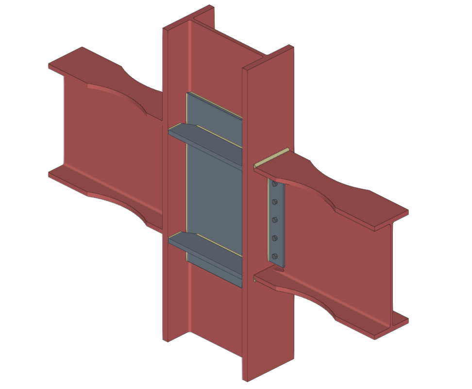
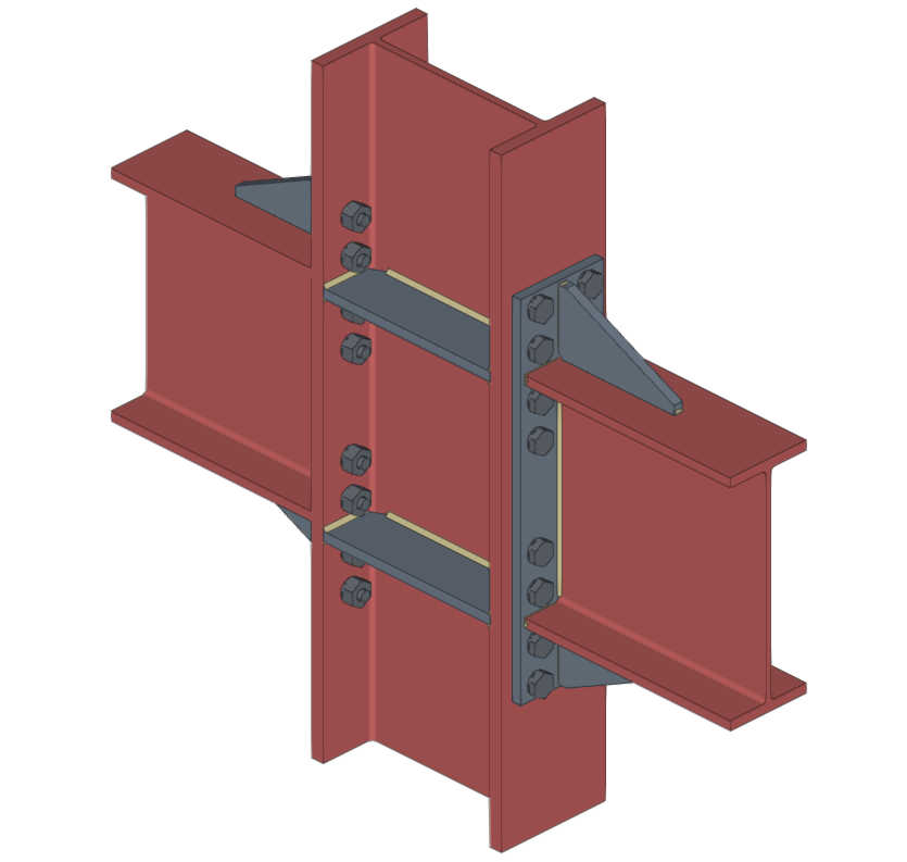
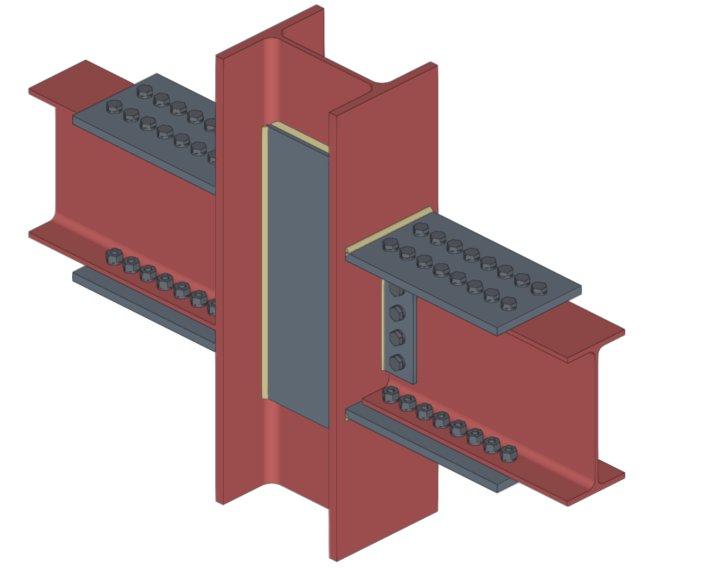
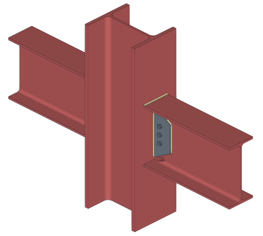
Checks on prequalified connections
In addition to the other checks carried out on the connection, the program carries out the specific checks defined in the AISC 341 and AISC 358 standards for prequalified connections.
These checks can be displayed on screen by selecting the "Prequalified connections" option, available in the corresponding drop-down in the "Analysis" tab of the connection editing window.
| Note: |
|---|
| Other operations can be defined at the same node where a prequalified connection has been inserted. This way, a different type of seismic-resisting system could be defined in each direction of the structure. In the direction where no pre-qualified connections are applied, the program will perform the usual checks after the finite element design. However, the prequalified connection check will not consider the effects of additional operations, displaying a warning in this case. |
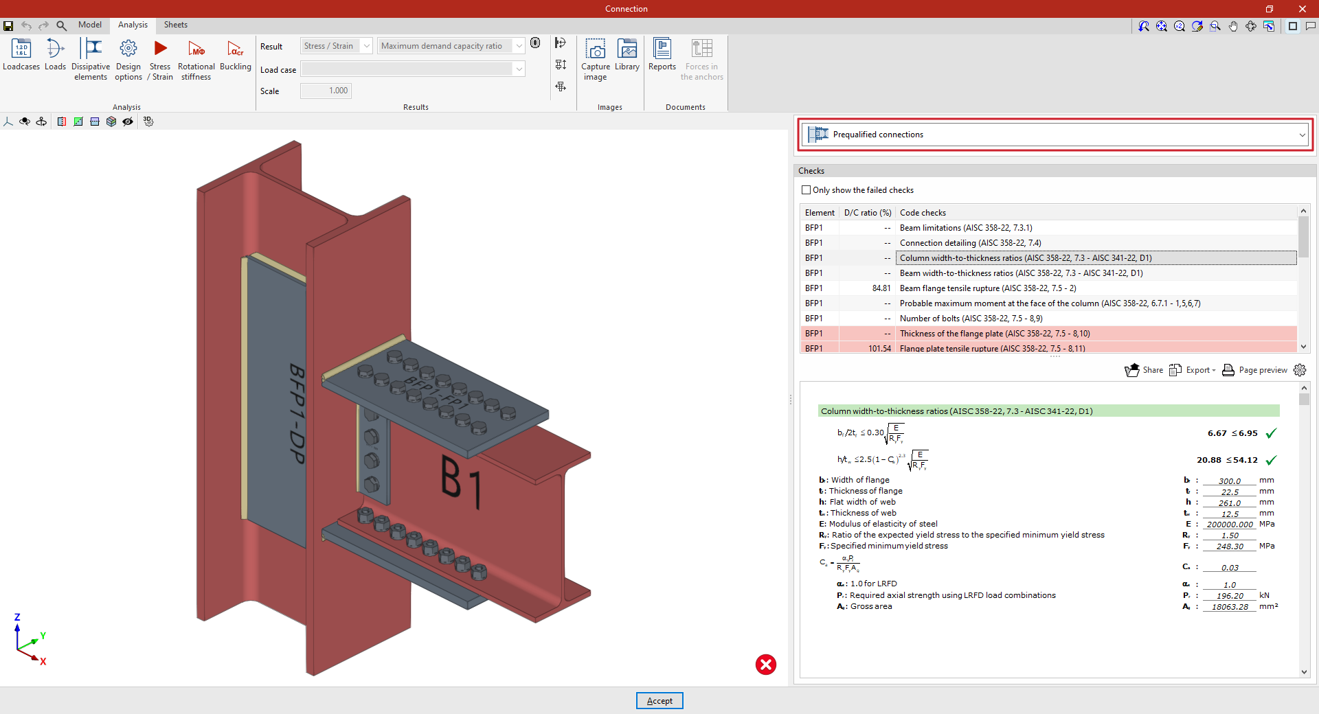
Prequalified connection check reports
The documents provided by the program include summarised and detailed reports of the checks carried out on the defined prequalified connections.
To obtain this, the corresponding sections of the report must be activated.