

"Stiffeners" function: plate stiffeners
The "Stiffeners" operation is used to insert stiffeners via a wizard in which their material, geometry, position and welds are defined.

Stiffeners can be inserted into the web of a section or into a plate.
| Example: |
|---|
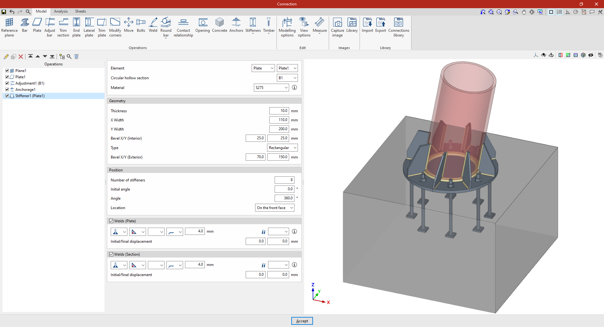
| In the example shown here, stiffeners are added between a plate and a circular hollow section. A plate has already been added to the base of the circular column, its geometry has been adjusted, and the anchor bolts have been defined on the foundation element. Next, stiffeners are added to the plate to improve its performance. |
Inserting plate stiffeners
Stiffeners can be inserted between a plate and a circular hollow section. To do this, click on the “Stiffeners” option in the top toolbar and select “Plate”.
Selecting the plate and the circular hollow section
First, specify the “Element” where the stiffeners are located – either a “Plate” or a “Section” – and select the corresponding “Circular hollow section”.
The stiffeners are arranged radially around the selected circular hollow section and parallel to the axis of the section.
Defining the geometry of the stiffeners
Next, the "Geometry" of the stiffeners is defined. This includes:
- Its “Thickness”,
- “Width X” and “Width Y” in the directions radial and perpendicular to the plate,
- The dimensions of the inner bevel ("Bevel X/Y (Inner)"),
- The “Type” of stiffener, either “Triangular” or “Rectangular”,
- And, in the case of rectangular stiffeners, the dimensions of the outer chamfer (“Chamfer X/Y (Outer)”).
Defining the position of the stiffeners
As regards the “Position” of the stiffeners, it should be noted that:
- The “Number of stiffeners” to be provided,
- The “Initial angle” at which the first one is located, measured from the position of the section’s local Y-axis,
- And the total “Angle” covered by the assembly, over which the stiffeners are distributed evenly;
- The “Location” of the stiffeners can be “On the front face” of the plate, “On the back face” or “On both faces”.
Defining the stiffener welds
Next, the “Welds” between the stiffeners and the “Plate”, and between the stiffeners and the “Section, are defined.
Within each section, the drop-down menus offer various options for specifying the position of the weld, the type of weld, the shape of the weld surface and the location where the work is to be carried out, either on-site or at a workshop.
You can also select the “Electrode” and specify whether the welds have an “Initial displacement” or “Final displacement”.
From here, once the model has been completed, users can continue by opening the “Analysis” tab to carry out the analysis of the connection.