

"Concrete" function
The "Concrete" operation allows concrete elements to be inserted into the connection. Anchors will be fitted to these, if necessary.

Inserting concrete elements
To insert a concrete element, click on the “Concrete” option in the top toolbar.
| Example: |
|---|
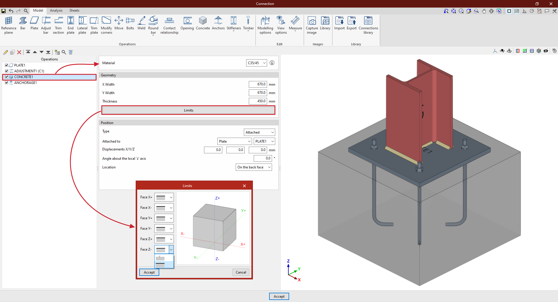
| In this example, a plate has been added to the base of column C1, and an adjustment operation has been performed on it to modify its geometry and insert the welds between the section and the plate. Next, a concrete element is inserted so that the connections between the plate and the concrete can be defined later. In this case, select “Attached” to “Plate” and choose the plate inserted from the corresponding drop-down menu. The “Location” of the element is “On the back face” From this point onwards, once the concrete element has been added, it can be selected in subsequent operations, such as “Anchors” Once the model is complete, you can continue by opening the “Analysis” tab to perform the analysis of the connection. |
Choice of material
First, specify the “Material” by selecting it from the drop-down menu of available concrete options.
By clicking on the button on the right, you can view information such as the “Reference” or the “Compressive strength” of the selected concrete.
Definition of the geometry of the concrete element
Next, define the “Geometry” of the concrete volume by entering the “Width X”, “Width Y” and “Thickness”.
By clicking the "Boundaries" button, you can use a series of drop-down menus to specify whether the element extends beyond each of the six faces of the concrete element in the model ("Face X+", "Face X-", "Face Y+", "Face Y-", "Face Z+" and "Face Z-") or whether these correspond to the element’s actual boundaries.
Definition of the position of the concrete element
To define the element’s “Position”, select either “Connection”, “Attached” or “Perpendicular” from the “Type” drop-down menu:
- In the “Type” drop-down menu, select “Connection” if you wish to define the position of the element by entering the “X”, “Y” and “Z” coordinates relative to the centre of the connection.
If you need to rotate the concrete element, you can enter the “Angle about the local ‘x’ axis”, the “Angle about the local ‘y’ axis” and the “Angle about the local‘Z’ axis”.
- In the “Type” drop-down menu, you can also select “Attached” or “Perpendicular” to indicate that the concrete element is attached to or perpendicular to a “Plate”, a “Bar” or a “Reference plane”
You can enter “X/Y/Z displacements”, if desired, as well as an “Angle about the local ‘z’ axis”
Finally, specify the “Location” of the element, which can be “On the front face” or “On the back face” of the element to which it is attached or perpendicular.