

"Bar" function
The "Bar" function in connection modelling allows you to add additional bars to the connection that have not been previously included in the node’s section definition, enabling you to simulate sagging, support elements, reinforcement brackets, etc.

Inserting the additional bar
To insert the additional bar, click on the “Bar” option in the top toolbar.
| Example: |
|---|
| In the example shown here, plates, bolts and welds have been added, and adjustment operations have been carried out on the connection sections. To complete the connection, an auxiliary bar is inserted between the plates welded to column C2 and beam B1. This bar was not previously included in the definition of the connection sections. |
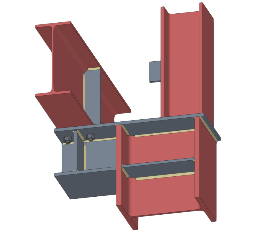
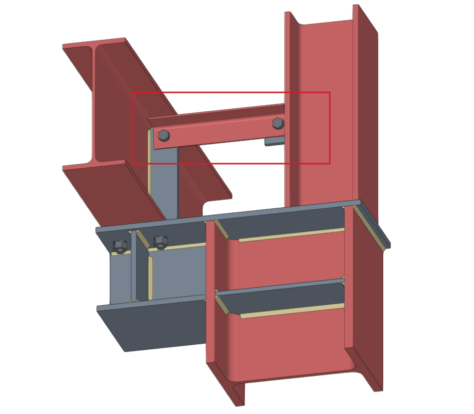
Model of the connection before and after the insertion of the additional bar
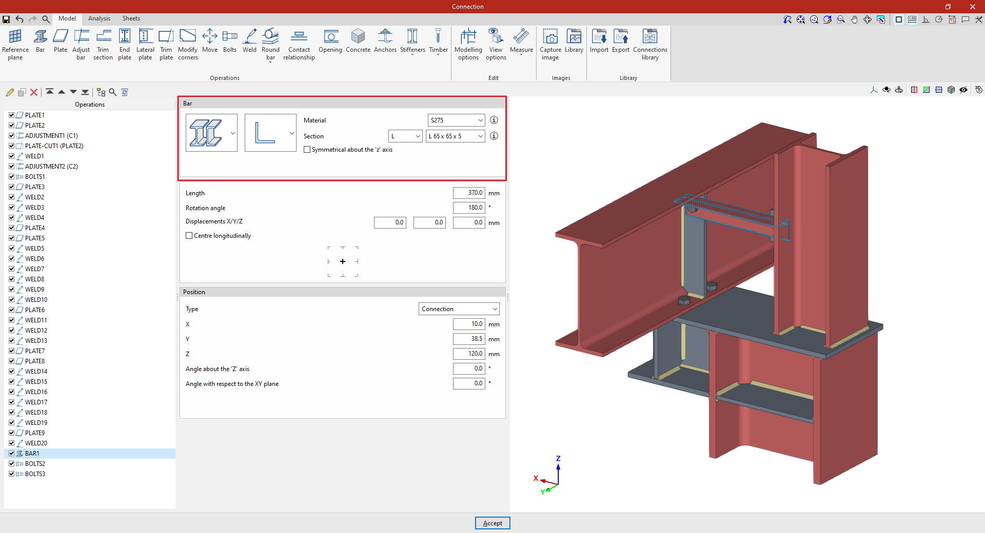
Selection of material and cross-section for the additional bar
In the “Beam” section, use the drop-down menus to select whether the section is made of rolled steel, formed steel, metal tubing or timber, and then select the type of cross-section:
- In the case of rolled steel bars, these may be rolled I, simple U, angle, T section, round bars or square bars
- In the case of shaped steel bars, these may be U-shaped, C-shaped, simple Z-shaped, stiffened Z-shaped, L-shaped or stiffened L-shaped
- In the case of steel hollow sections, these may be rectangular or circular hollow sections
- And in the case of wooden bars, the cross-section is solid rectangle
On the right, select the “Material” from the drop-down menu.
Next, select the "Section" from the drop-down menus below, choosing a specific section from the available series and a particular section within that series.
The information buttons on the right allow you to view the material properties and the geometric properties of the section.
On the right-hand side, you can specify the “Resistance depending on the thickness”.
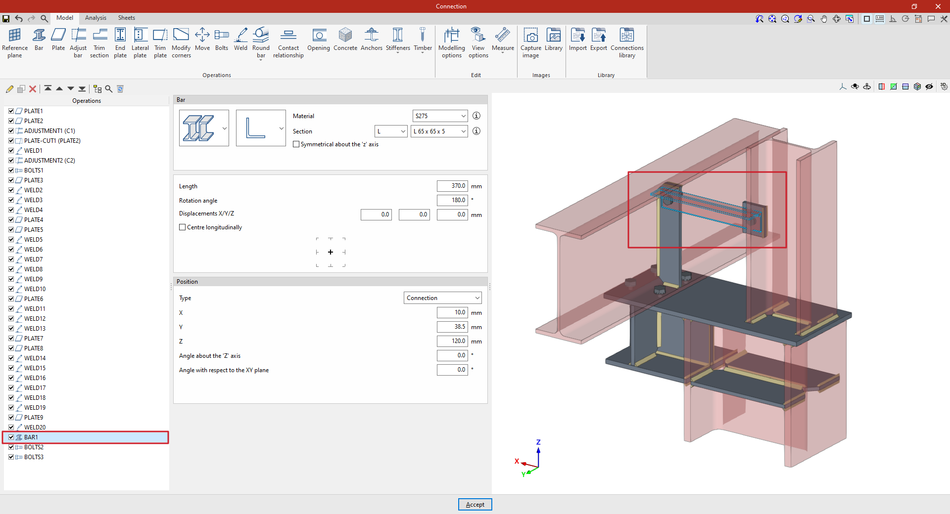
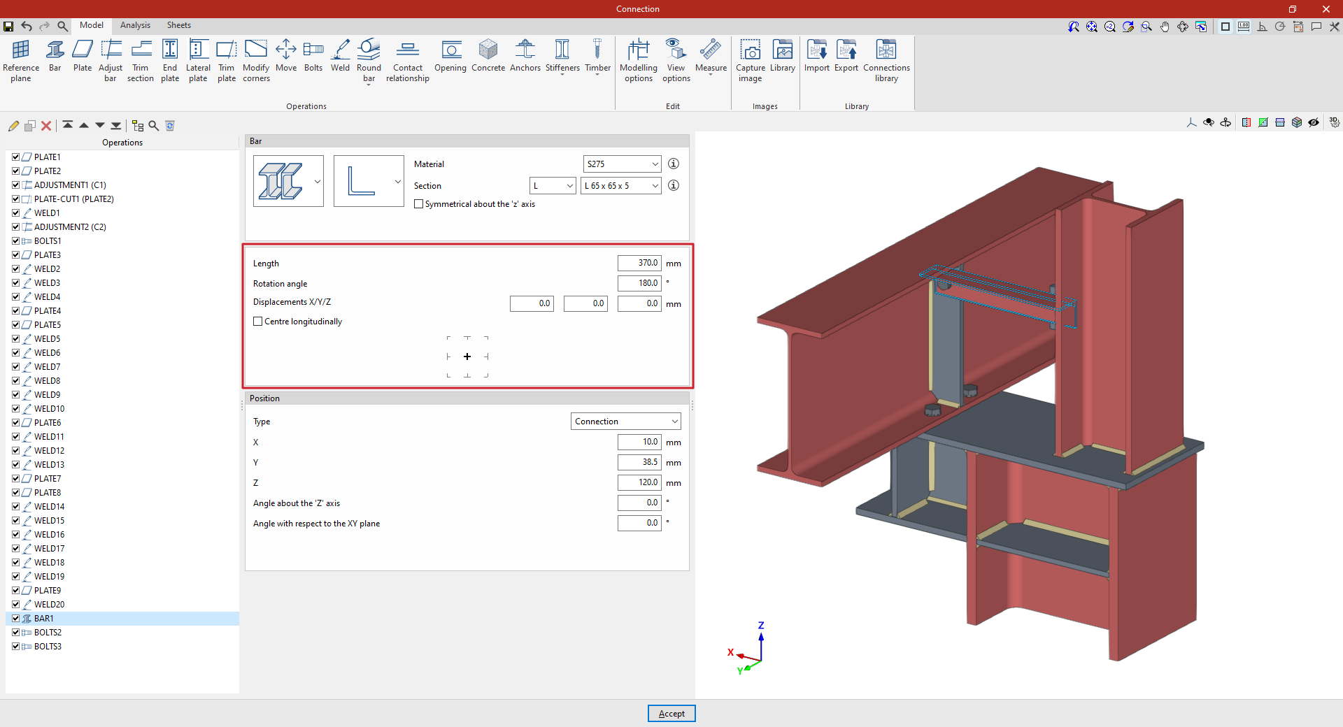
Determining the length and positioning of the additional bar
Next, enter the “Length” of the section.
The following parameters allow you to adjust the bar’s layout. The “Rotation angle” and the “X displacement”, “Y displacement” and “Z offset” refer to the section’s local coordinate system. For example, you can enter a value of 180 degrees, with no offsets, to rotate the section about its axis. These offsets modify the bar’s position relative to its default position.
If the "Centre longitudinally" checkbox is ticked, the section will be positioned so that its longitudinal centre coincides with the reference point defined in the following section. If it remains unticked, the end of the section will be aligned with that point.
Further down, you can select the reference point for the additional bar in the diagram: either the axis of the section, the centre of one of its faces, or one of its corners.
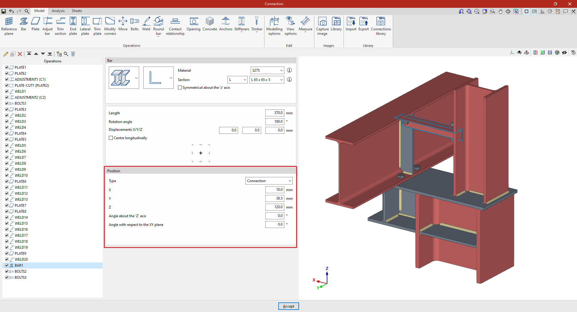
Adjusting the position of the additional bar
The “Position” section defines the reference point for the bar’s position. This can be one of the following, depending on the selection made in the “Type” drop-down menu:
- If "Connection" is selected, the additional bar will be positioned using the centre of the connection as a reference. The "X", "Y" and "Z" distances from the section's local coordinate origin to the centre of the connection are then specified.
Furthermore, the “Angle about the Z-axis” or vertical axis of the connection allows a rotation in plan view, and the “Angle with respect to the XY plane” applies a rotation in the vertical plane containing the section. - If you select "In the direction of a bar", the additional bar you enter will be positioned along the direction of the selected bar. First, select an existing "Bar".
From here, you can enter "X/Y/Z displacements" in the local coordinates of that beam, as well as enter the "Angle around the local 'y' axis" and the "Angle around the local 'z' axis" of the selected beam to adjust the orientation of the additional beam relative to it.
At the bottom, you can also select the reference point for the additional beam in the diagram, whether this is the centreline of the section, the centre of one of its faces, or one of its corners.
From this point onwards, you must add the remaining operations required to complete the connection model before you can perform the “Analysis” for it in the relevant tab.