

"Move" function
The "Move" function allows you to move bars or plates using another element as a reference.

Defining the movement of plates and/or bars
To start the operation, click on the “Move” option in the top bar.
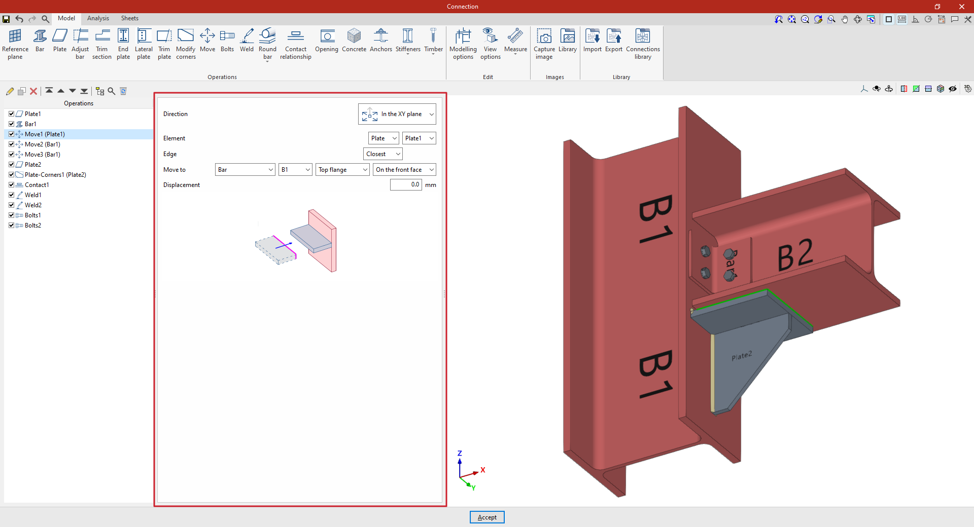
Firstly, the “Direction” of movement of the element is specified in relation to its axes, either “In the Z axis” or “In the XY plane”.
Next, specify the “Element” to be moved, whether it is a “Plate” or a “Bar”, indicating in this case the plate or section of the bar to be considered for the movement.
Next, you must specify the “Edge” you wish to use as a reference point for the movement, whether it is the “Nearest”, the “Furthest” or one specified by the “User”.
Finally, you specify that you wish to “Move to” another “Plate”, another “Bar” or a “Reference plane”, and you can also select “On the front face” or “On the back face” to indicate which face defines the movement.
If necessary, an additional “Displacement” can be applied to the movement.
In this way, the plate moves in its plane until one of its edges reaches the plane defined by the face of the specified element, or the bar is moved by selecting its plates, until its faces are flush with the faces of other elements. For this movement to be possible, both faces must be parallel.
If the reference element changes its dimensions or position, the selected element moves with it automatically.
Example
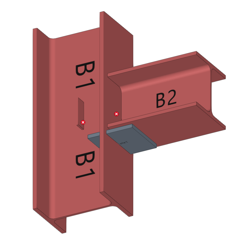
In this example, a plate has been inserted beneath the beam, and an angle section has also been added to form the connection between the beam and the column.
These elements are then moved to adjust their position.
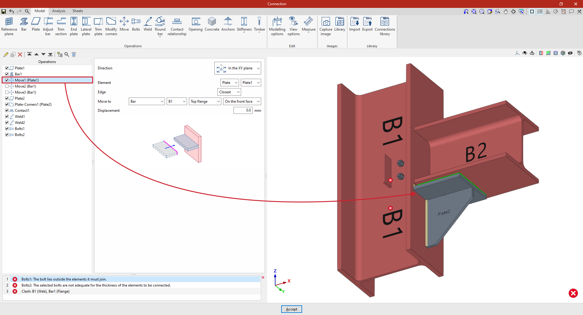
- In the first step, select “In the XY plane” and choose the “Nearest” edge. The plate moves to “Bar” “B1”, specifically to the “Upper flange”, and is positioned “On the front face”.
Later on, you can add new “Move” operations to adjust the position of the angle section:
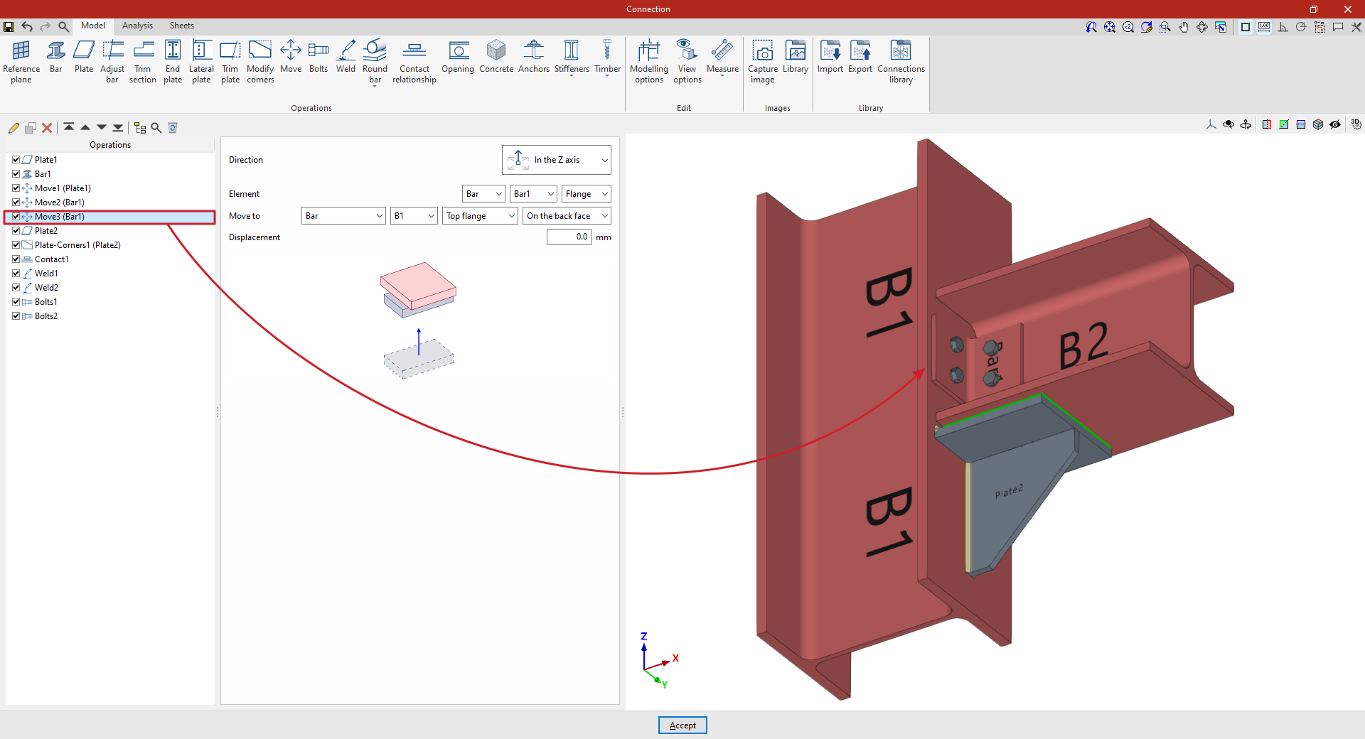
- In the first of these, you specify that you wish to move the beam “Along the Z-axis” and select the “Beam” corresponding to the angle bracket as the “Element”. In the drop-down menu on the right, select the section flange to be considered in the movement; in this case, the “Web”.
Next, specify that you wish to “Move to” the web of beam B2, positioning it “On the back face”.

- By copying the operation, you can define a second adjustment movement. In this case, for the same beam, you specify that you wish to move its “Flange” to the “Top flange” of column B1.
From this point onwards, you should add the remaining operations required to complete the model. Once this is done, you can continue by opening the “Analysis” tab to carry out the connection analysis.